Page is loading ...

1610 Interstate Drive Champaign, IL 61822
(217) 398-8970, Ext. 2
airsupport@hobbico.com
READ THROUGH THIS MANUAL BEFORE STARTING CONSTRUCTION. IT CONTAINS IMPORTANT
INSTRUCTIONS AND WARNINGS CONCERNING THE ASSEMBLY AND USE OF THIS MODEL.
WARRANTY
Hobbico
®
guarantees this kit to be free from defects in both material and workmanship at the date of purchase. This warranty
does not cover any component parts damaged by use or modification.In no case shall Hobbico’s liability exceed the original cost
of the purchased kit. Further, Hobbico reserves the right to change or modify this warranty without notice.
In that Hobbico has no control over the final assembly or material used for final assembly, no liability shall be assumed nor
accepted for any damage resulting from the use by the user of the final user-assembled product. By the act of using the
user-assembled product, the user accepts all resulting liability.
If the buyer is not prepared to accept the liability associated with the use of this product, the buyer is advised to return
this kit immediately in new and unused condition to the place of purchase.
HCAZ3084 for HCAA2020 V:1.0 © Copyright 2002
See more of our products at
www.hobbico.com
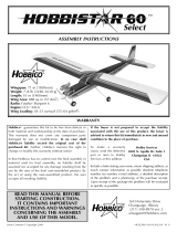
Wingspan: 60 in [1524mm]
Wing Area: 660 sq in [42.6dm
2
]
Weight: 5.5 lbs [2495g]
Wing Loading: 19 oz/ sq ft [58 g/dm
2
]
Engine: .40 cu in [6.5cc] two-stroke
Radio: 4-channel, 4 servos
™

Congratulations and thank you for purchasing the Hobbico
SuperStar .40
™
ARF. You’ve made the right decision by
purchasing a “real” model airplane with a .40-size engine and a
4-channel radio. Once assembled and set up, there will be no
fiddling with a temperamental engine or constant
troubleshooting to figure out how to get the model to fly. Under
the guidance of an experienced flight instructor, all you’ll have
to do is concentrate on learning to fly. And after you’ve
mastered the SuperStar, the engine and radio may be installed
in your next model!
Join the AMA (Academy of Model Aeronautics). In addition
to other vital functions, the AMA, the governing body of model
aeronautics in the United States, provides insurance to
members who comply with the Safety Code. You must be a
member to fly at R/C clubs chartered by the AMA–most of
which are. The AMA can also direct you to the closest club
whose membership should have qualified flight instructors. To
join the AMA, telephone, write or fax them at the address
below, or join on-line at www.modelaircraft.org.
Academy of Model Aeronautics
5151 East Memorial Drive
Muncie, IN 47302-9252
Tele. (800) 435-9262
Fax (765) 741-0057
Or via the Internet at:
www.modelaircraft.org
1.Your SuperStar .40 ARF should not be considered a toy, but
rather a sophisticated, working model that functions very much
like a full-size airplane.Because of its performance capabilities,
the SuperStar .40 ARF, if not assembled and operated
correctly, could possibly cause injury to yourself or spectators
and damage to property.
2.You must assemble the model according to the
instructions.
Do not alter or modify the model, as doing so may result in an
unsafe or unflyable model. In a few cases the instructions may
differ slightly from drawings or sketches. In those instances the
written instructions should be considered as correct.
3.You must check the operation of the model before every flight
to insure that all equipment is operating and that the model has
remained structurally sound. Be sure to check clevises or other
connectors often and replace them if they show any signs of
wear or fatigue.
We, as the kit manufacturer, provide you with a top quality kit and
instructions, but ultimately the quality and flyability of your finished
model depends on how you build it; therefore, we cannot in any
way guarantee the performance of your completed model, and no
representations are expressed or implied as to the performance or
safety of your completed model.
Protect Your Model,Yourself
and Others...Follow these
Important Safety Precautions
IMPORTANT
Once mastered, piloting a model aircraft can be one of the
most enjoyable hobbies around. However, it cannot be
stated strongly enough that, if you do not already know how
to fly an R/C airplane, you will probably not be able to fly this
model by yourself.It may appear to be easy, but over-
controlling
and disorientation quickly overcome inexperienced fliers,
swiftly ending their first flight. The best thing you can do to
insure success is to find a flight instructor who will inspect
your model for airworthiness and provide flying lessons. If
you haven’t yet done so, contact the local hobby shop
and ask them to introduce you to an instructor or an R/C
club representative. If there is no club or experienced R/C
pilot nearby, it would be worth even a long drive to find
one–if only for just a few flight lessons (then you’ll have an
idea of what to expect).
Introduction
2

A four-channel radio control system is required to fly this model.
“Four-channels” means that the system is capable of controlling
four separate functions in the plane. In the case of your
SuperStar, this would be ailerons, elevator, rudder and
throttle. If purchasing a new system, be certain it comes with
four servos (some systems come with only three servos, so a
fourth may have to be purchased separately). A 6" servo
extension wire for the aileron servo is also required (see the
“Hardware” list on this page), but some radio control systems
include the extension. So, it may not have to be purchased
separately.
A .40 cu in [6.5cc] 2-cycle model engine and suitable propeller
(and spare propellers) are also required to fly the SuperStar.
The number .40 refers to engine displacement in cubic inches.
Most .40 cu in engines recommended for this model run well
with a 10 x 6 propeller (but consult the engine manufacturer’s
instructions to be certain). When sizing a propeller, the first
number refers to the propeller diameter in inches.The second
numbers refers to the propeller pitch in inches.
There are two types of glue that are
recommended for assembling this
model.The first type, Cyanoacrylate, is
more commonly known as “super glue.”
Most modelers just call it “CA.” CA
comes in different viscosities
(thickness).
Both thin and medium viscosity are
recommended for this model and are
listed in the
Building Supplies
section that follows. Thin CA
rapidly absorbs into wood and is best for bonding parts that are
already together. Thin CA is also required for gluing in the
hinges (as you will see when you get to that part of assembly).
Medium CA is good for joining parts that require positioning
before joining them together, or for filling small gaps in parts
that don’t fit perfectly. CA doesn’t always cure immediately.
When instant curing is required, CA “activator” can be applied
to make the CA harden right away. Activator (also known as
“accelerator”) is usually sprayed out of a small bottle.
One accessory recommended for
applying CA is CA Applicator Tips
(HCAR3780). These small tips fit on
the top of the bottle and help direct and
control the amount of CA that comes
out. When the tip becomes clogged,
just cut off the end and keep going. After the applicator tip
becomes too short, just replace it with another.
The second type of adhesive that is
used for assembling this model is
epoxy. There are different working
times for epoxy (5-minute, 15-minute,
30-minute, etc.), but 30-minute is
recommended. Longer working time
allows more time for positioning and
joining the parts, and provides a
stronger bond as more epoxy can be absorbed into the
material before it
hardens. Epoxy is also recommended for
fuelproofing bare
wood.
In addition to the radio and engine, the following items will
also be required:
Adhesives & Tools
❏ 1/2 oz. [15g] Thin Pro
™
CA (GPMR6001)
❏ 1/2 oz. [15g] Medium Pro CA+ (GPMR6007)
❏ Pro 30-minute epoxy (GPMR6047)
❏ #1 Hobby knife (HCAR0105)
❏ #11 blades (5-pack, HCAR0211)
❏ Drill bits: 1/16" [1.6mm], 3/32" [2.4mm]
❏ Small metal file
❏ 1/16" hex driver wrench (“Allen” wrench)
❏ Masking tape (TOPR8018)
❏ Pro Threadlocker thread locking compound
(GPMR6060)
❏ Denatured alcohol (for epoxy clean up)
Hardware
❏ 6" [150mm] Servo extension wire (HCAM2701 for
Futaba
®
)
❏ R/C foam rubber (1/4" [6mm] – HCAQ1000, or 1/2" [13mm]
– HCAQ1050)
❏ 3' [900mm] Standard silicone fuel tubing (GPMQ4131)
Optional Items
The following items are not absolutely necessary, but are
mentioned
in the manual and will assist in assembling your model.
❏ 21st Century
®
sealing iron (COVR2700)
❏ CA applicator tips (HCAR3780)
Building Supplies
IMPORTANT: Read the warning labels on all glue containers. Be
especially certain to use CA in a well-ventilated area.After applying
CA, step back or look away from the work to avoid the vapors. CA
bonds skin immediately. If this happens, CA debonder or acetone
fingernail polish remover will dissolve the CA after a few minutes.
Never point the CA tip toward your face and be careful when
opening a clogged tip.
Notes About Glue
Additional Items Required
3

❏ Epoxy brushes (6, GPMR8060)
❏ Mixing sticks (50, GPMR8055)
❏ Mixing cups (GPMR8056)
❏ Builder’s Triangle Set (HCAR0480)
❏ Precision Magnetic Prop Balancer
™
(TOPQ5700)
When ready to fly, you’ll need the equipment to fuel the plane
and start the engine. Perhaps you’ve already made
arrangements with the R/C club or your flight instructor to
borrow their equipment, but eventually you’ll want to get your
own. Some of the items are photographed or listed on the side
of the kit box cover. Additionally, a field box will be required to
carry the equipment.
Before beginning assembly, inspect the parts in this kit to make
sure they are of acceptable quality. If any parts are defective or
damaged, or if you need assistance with assembly, contact
Product Support.
Hobbico Product Support:
Phone: (217) 398-8970
Fax: (217) 398-7721
E-mail: airsuppor[email protected]
Kit Inspection
Field Equipment
4

5
Parts List
❏ 1. Wing
❏ 2. Fuselage (nose gear factory installed)
❏ 3. Fin with rudder
❏ 4. Stabilizer with elevator
❏ 5. Main landing gear wires
❏ 6. 2-3/4" main wheels
❏ 7. 1/4" dowels
❏ 8. Plywood aileron servo mount
❏ 9. Plywood pushrod tube brace
❏ 10. Fuel tank w/hardware
❏ 11. Plywood fuselage servo tray
❏ 12. Plywood wing joiners
❏ 13. 2" spinner
❏ 14. These parts not used
❏ 15. Hardware
(see detailed list below)
Hardware
(2) Brass body for screw-lock pushrod
connector (throttle, nose steering)
(6) 6-32 Blind nuts (factory-installed,
4-
engine mount, 2-nose gear mount)
(2) Nylon control horns (1-elevator,
1-
rudder)
(1) 5/32" Nylon nose steering arm (factory
installed)
(5) Nylon clevis (2-ailerons, 1-elevator,
1-
rudder)
(2) Nylon landing gear straps (main
landing gear)
(15) CA hinges
(4) Nylon Faslinks (2-ailerons, 1-elevator,
1-rudder)
(2) Nylon torque rod horns (aileron
torque rods)
(2) 3/16" Gray pushrod tubes (elevator,
rudder, throttle, antenna guide)
(5) Silicone retainers (for clevises)
(7) 6-32 x 1/8" Socket set screws (6-wheel
collars, 1-nose gear collar)
(1) 6-32 x 1/4" Socket-head cap screw
(nose steering arm)
(2) 4-40 x 1/4" Socket-head cap screws
(screw-lock pushrod connectors)
(6) 6-32 x 3/4" Screws (factory-installed,
4-engine mount, 2-nose gear mount)
(8) 5/32" Wheel collars (6-wheels, 1-nose
steering arm, 1-nose gear)
(1) 17-1/2" Wire pushrod (throttle)
(2) 36" Wire pushrods (1-elevator, 1-rudder)
(2) 6" Wire pushrods (ailerons)
(6) #6 Washer (factory installed, 4-engine
mount, 2-nose gear mount)
(4) 2-56 x 1/2" Screw (elevator and rudder
control horns)
(8) #2 x 1/2" Screw (4-main landing gear
straps, 4-servo tray)
(12) #64 Rubber bands
(1) Engine mount (factory installed)
(2) Metal engine mounting straps
(4) 4mm Nuts (engine mounting)
(4) 4mm Washers (engine mounting)
(4) 4mm Lock washers (engine mounting)
(4) 4 x 25mm Screws (engine mounting)
(1) Nose gear mount (factory installed)
1
2
3
4
1
13
15
11
10
12
14
14
6
6
5
5
7
8
9

Hinge the Ailerons
Start with the right wing first.
❏ ❏ 1. Carefully remove the masking tape holding the aileron
to the wing. Also remove the protective foam block on the
aileron torque rod.
❏ ❏ 2. Use a hobby knife with a #11 blade to “loosen-up” the
precut hinge slots in the wing to help the hinges go in easier.
This is done by inserting the blade into the hinge slot and
moving it from side-to-side several times. Note that the back
edge of the blade is the part that does the work.
❏ ❏ 3. Insert a CA hinge halfway into each hinge slot in the
aileron.Test fit the aileron to the wing and to the aileron torque
rod with the hinges.
❏ ❏ 4. Mark the exact location of the hinges by cutting small
slits through the covering on both sides of the hinges in the
wing and aileron.
❏ ❏ 5. Remove the aileron from the wing and take out the
hinges.Cut a small strip of covering from the hinge slots in the
aileron and the wing between the slits you cut. Hint: Use a
small metal straightedge as a cutting guide.
❏ ❏ 6. Lay a few paper towels neatly on top of each other.
Use a pair of scissors to cut them into small squares. These
paper towel squares will come in handy throughout the
assembly process (and will save you from wasting whole paper
towels for small jobs).
❏ ❏ 7. Mix a small batch of 30-minute epoxy. Use a toothpick
or a small piece of wire to work some epoxy into the hole and
the groove in the aileron for the torque rod. Also coat the torque
rod with epoxy.
❏ ❏ 8.Join the aileron to the wing with the hinges. Be certain
that the hinges remain centered. If any hinges do not remain
centered, stick a pin through the hinge near the middle, then
rejoin the aileron to the wing. Pull out any pins you may have
used. Use a paper towel square to wipe away epoxy that has
squeezed out of the aileron.
Assemble the Wing
6

❏ ❏ 9. Position the aileron so there is a small gap between
the aileron and the wing–just enough to see light through or to
slip a piece of paper through. Add six drops of thin CA to the
top of each hinge.Wait a few seconds between drops to allow
the CA to fully soak in so it does not get into the gap. After
gluing the tops of all the hinges, flip the wing over and add six
drops of CA to the bottom of each hinge.Keep the paper towel
squares close by to absorb excess CA that doesn’t get into the
hinges.
❏ 10. Return to step 1 and hinge the left wing the same way.
Join the Wing Halves
❏ 1. Use epoxy to securely glue together both 1/8" [3mm]
plywood wing joiners. Clamp the joiners together and wipe
away excess epoxy that squeezes out.
❏ 2. After the epoxy from the previous step has hardened, test
fit the joiner in one, then the other wing half.Test join the wings
with the joiner.
❏ 3. Lay one wing panel flat on your workbench. Measure the
distance between the bottom of the raised end of the wing and
the workbench. The measurement should be 3-1/4" to 4-1/4"
[80mm to 110mm].
❏ 4.Separate the wings.Cut out the sheeting so the servo can
go half-way in. If necessary, enlarge the cutout in the rib so the
servo will fit. Prepare the other wing half the same way.
❏ 5.Mix up 1/2 oz. [15ml] of 30-minute epoxy.Working quickly,
pour a generous amount into one of the wing halves where the
joiner goes. Use a piece of stiff wire or something similar to
spread the epoxy all around the inside to coat all the surfaces.
Thoroughly coat one half of the joiner with epoxy as well.
Insert
the coated end of the joiner into the wing. Coat the rib on the
end of the wing with epoxy (an epoxy brush works well for this).
❏ 6. Use the remainder of the epoxy to coat the protruding end
of the joiner and the inside of the opening in the other wing half.
Join the wings and use your paper towel squares to wipe away
excess epoxy as it squeezes out.
7

❏ 7. Tightly tape the wing halves together with several strips
of masking tape on the top and bottom. Continue to wipe away
excess epoxy as it comes out. Be certain the front and back of
both wings accurately align. Do not disturb the wing until the
epoxy has hardened.
Hook Up the Ailerons
❏ 1. Cut the covering from the bottom of the wing for the 1/8"
[3mm] plywood aileron servo mount. Glue the servo mount to
the wing with epoxy. Make sure the mount is level and fill the
gap on both sides with epoxy.
Refer to this photo for the following seven steps.
❏ 2. Cut a hole in the sheeting so the servo wire can come
through (the hole can be seen in the photo at step 6).Guide the
servo wire out the hole and install the servo.
❏ 3. Use wire cutters to cut two of the arms off a four-arm
servo arm. Install the arm on the aileron servo.
❏ 4. Drill 1/16" [1.6mm] holes through the servo mount for the
servo mounting screws, then temporarily mount the servo using
the eyelets, rubber grommets and screws that came with it.
Remove the screws, add a few drops of thin CA to the holes,
allow to fully harden, then remount the servo. This process is
important to harden the “threads” in the wood so the screws
remain tight.
❏ 5.Thread the nylon torque rod horns onto the aileron
torque
rods until the horns are even with the ends of the torque rods.
❏ 6.Thread a nylon clevis twenty full turns onto a 6" [150mm]
wire pushrod that is threaded on one end. Connect the clevis
to the torque rod horn. Align the pushrod with the servo arm,
then use a fine-point felt-tip pen to mark the pushrod where it
crosses the servo holes. Note: The aileron must be centered
during this procedure (the bottom of the aileron should be even
with the bottom of the wing).
8

❏ 7. Disconnect the pushrod from the torque rod horn. Use
pliers to make a 90° bend in the pushrod at the mark you
made. Fit a nylon Faslink to the pushrod, then cut off the
excess pushrod 1/16" [2mm] above the Faslink.
❏ 8. Enlarge the holes in the servo arm with a #48 or 5/64"
[2mm] drill or a hobby knife. Connect the pushrod to the third
hole out on the servo arm. Note: If using servo arms different
than the Futaba servo arms shown in this manual, connect the
pushrod to a hole that is as close as possible to 17/32" [13mm]
from the center.
9. Make and connect the other pushrod the same way.
Now the wing is finished. Set it aside while working on the
fuselage.
Mount the Landing Gear
❏ 1. Use a small metal file to file a 1/8" [3mm] wide “flat spot”
1/8" [3mm] from the end of both main landing gear wires.
❏ 2. Mount the wheels to the landing gear with a 5/32" wheel
collar on both sides of each wheel. Add a small drop of non-
permanent thread locking compound (such as Great Planes
Threadlocker GPMR6060) to two 6-32 set screws and thread
them into the collars using a 1/16" hex (“Allen”) wrench.
Position the wheel collars, then tighten the set screws. Be
certain the set screw in the outer wheel collar is in the flat spot.
❏ 3. Use a hobby knife with a #11 blade to round the inner
edges of the holes in the landing gear rail in the bottom of the
fuselage for the main landing gear. This way, the landing gear
wires will go all the way down. Fuelproof the bare wood in the
groove by applying a light coat of epoxy.
#2 x 1/2" [13mm] screw
❏ 4. Insert the main landing gear wires into the holes, then drill
1/16" holes for the nylon straps. Mount the gear to the bottom
of the fuselage with the straps and four #2 x 1/2" [13mm]
screws.
Assemble the Fuselage
9

Mount the Stab and Fin
❏ 1. Use 30-minute epoxy to securely glue in the 1/4" [6mm]
wing dowels.The longer dowel goes in front.After positioning
the dowels, lightly coat them with epoxy so they will be
fuelproofed.
❏ 2.The same way you joined the ailerons to the wing, cut the
covering from the hinge slots and join the elevator to the stab
and the rudder to the fin with the hinges. Use thin CA to
permanently glue in the hinges.
❏ 3. Taking accurate measurements, use a fine-point felt-tip
pen to mark the center of the stabilizer on the trailing edge.
Insert the stabilizer into the fuselage. Center the mark on the
aft end of the fuselage, then stick a pin through the fuselage
and the stab to hold it in position.
❏ 4. Use a fine-point felt-tip pen to mark both ends of the stab
where the leading edge meets the tip under the covering.
❏ 5. Measure the distance between the fuselage and the
marks on both sides of the stab. Adjust the stab until both
measurements are equal and the stab is centered.
❏ 6. Using a fine-point felt-tip pen, draw lines around the top
and bottom of both sides of the stabilizer where it goes into the
fuselage.
❏ 7.Take the stab out of the fuselage. Refer to the
Expert Tip
that follows, or use a hobby knife with a new, sharp #11 blade
to cut along the covering 1/32" [1mm] inside the lines you
marked.Use great care to cut only into the covering and not
10

into the balsa beneath. Cutting too deep will weaken the
structure, possibly causing the stab to break during flight.
❏ 8. Peel the covering from the stab. Use one of your paper
towel squares lightly moistened with denatured alcohol to wipe
the ink from the stab and the fuselage.
❏ 9. Mix 1/4 oz. of 30-minute epoxy. Apply epoxy to both sides
of the stab where it contacts the fuselage and in the fuselage
where it contacts the stab. Slide the stab into position and
center-it-up as you did with the pin and by taking
measurements as in steps 3 & 5.Wipe away excess epoxy. Do
not disturb the fuselage until the epoxy has hardened.
❏ 10.Test fit the fin in the fuselage. Similar to what was done
for the stab, mark the outline of the fin onto the top of the
fuselage, then cut away the covering and wipe away the ink.
❏ 11. Glue the fin into the fuselage with 30-minute epoxy. Be
certain to apply epoxy to both the fin and the fuselage where
they contact each other. Immediately after inserting the fin and
before the epoxy hardens, use a builder’s triangle to make
certain the fin is perpendicular to the stab. If it is not, use
masking tape to pull the fin to one side or the other to get it
vertical.
Mount the Engine and Radio Tray
❏ 1.Mount the engine to the mount with two metal straps, four
4 x 25mm screws and 4mm lock washers and 4mm nuts. Be
certain the engine is pointing straight ahead, and is not slanted
off to one side or the other.Note that the lock washers go under
the heads of the screws. Be certain the engine is centered and
that the screws are evenly tightened.Do not use a small, hobby
screwdriver to tighten the screws. A large (No. 2) Phillips
screwdriver is preferred.
An alternate way to cut the covering over the stabilizer is to
use a soldering iron. This way, you will not risk accidentally
cutting into the balsa. A fine soldering tip is not necessary,
but does work best. Using a metal straightedge as a guide,
move the soldering iron just fast enough to melt through the
covering. Be careful not to burn the wood, otherwise you will
have defeated the purpose of using a soldering iron to cut
only the covering.
11

❏ 2.Balance the propeller and spare propellers.Most .40-size
engines that will be used on this model run best with a 10 x 6
(10" diameter, 6" pitch) propeller, but refer to the
manufacturer’s
recommendations that came with your engine. The Top Flite
Power Point Precision Magnetic Propeller Balancer
(TOPQ5700)
is illustrated in the photo.
❏ 3. Mount the back plate of the spinner and the propeller to
the engine.Tighten the propeller nut “finger-tight,” then use the
appropriate-size wrench (10mm for most .40 engines) or a
crescent wrench to fully tighten the nut. 1/2-turn, plus 1/8 turn
should be sufficient.Note: Do not install the muffler until
instructed
to do so.
❏ 4. Prepare the fuel tank as shown in the photo, first by
inserting two aluminum tubes through the rubber stopper,
followed by the metal plates and the screw. Bend one of the
tubes upward so it will be near the top of the tank when the
stopper is inserted. This tube will be connected to the muffler
and serves both as an overflow line (to signify when the tank is
full) and as a pressure line to provide muffler pressure to the
tank. Connect the clunk to the other tube with the silicone tube
that came in the tank. Note that the silicone tube must be cut
to the correct length, so that when the tank is assembled, the
clunk does not contact the back of the tank. Otherwise, the
clunk could become stuck near the top of the tank, thus
discontinuing fuel flow.
❏ 5.Insert the rubber stopper in the tank, then securely tighten
the screw. Shake the tank and listen for the clunk inside. If the
clunk stops making noise, the fuel line may be too long and the
clunk may have become stuck. Disassemble the tank and
shorten the fuel line as necessary.
❏ 6. Install the fuel tank in the fuselage with the neck of the
tank protruding through the hole in the firewall. Make certain
you have installed the tank upright (with the pressure tube
inside the tank pointing upward).
❏ 7.Test fit the 1/8" [3mm] plywood radio tray in the fuselage
over the four pre-glued mounting blocks. If necessary, use a
hobby knife to trim the notches in the battery tray so it will fit.
Note:The battery tray also keeps the fuel tank from shifting aft.
❏ 8. Wrap the battery pack and receiver in 1/4" [6mm] R/C
foam rubber (if 1/4" R/C foam rubber is not available, 1/2"
[13mm] is suitable–it just takes up a little more space).
Securely mount the battery and receiver to the radio tray with
the Velcro strips included with the kit.
12

❏ 9. Mount the radio tray in the fuselage with the #2 x 3/8"
[10mm] screws.
Mount the Servos
❏ 1. Make two 18" [460mm] pushrod tubes from the 3/16"
[4.8mm] gray pushrod tubes supplied with this kit. (It doesn’t
matter which tubes you cut them from as there will be plenty of
tubing leftover anyway.) Thoroughly roughen both ends of the
tubes with coarse sandpaper so glue will adhere. Do not use
any glue until instructed to do so.
❏ 2. Enlarge the holes in the fuselage so the pushrod tubes
will go through. The holes should be long enough to
accommodate the tubes at a small angle as shown in the
sketch above.
❏ 3.Guide the tubes through the holes up through the
fuselage
into the radio compartment.
❏ 4. Fit the tubes through the 1/8" [3mm] plywood pushrod
brace, then position the brace behind the former as shown.
Refer to this photo while installing the servos and hooking
up the pushrods.
❏ 5. The same as was done for the aileron servo, make one
two-arm servo arm and two one-arm servo arms by cutting off
the unused arms. Save two of the cut off arms for use later
when hooking up the antenna.
❏ 6. Install a brass screw-lock pushrod connector in the third
hole out into the two-arm servo arm (or, like the aileron servo
13

arm, to a hole that is as close to 17/32" [13mm] as possible).
Secure the connector with a nylon retainer.
❏ 7. Place the servos in the servo tray as shown in the photo
at step 5. Drill 1/16" [1.6mm] holes through the servo tray for
mounting the servos. Mount the servos in the tray with the
screws that came with the servos.
❏ 8. Remove the screws and the servos.“Harden” the holes in
the servo tray with a drop of thin CA in each hole. Allow to fully
harden, then reinstall the servos with the screws.
❏ 9.Insert the nose-steering pushrod into the screw-lock pushrod
connector on the rudder servo.
❏ 10.Thread a nylon clevis onto a 36" [910mm] wire pushrod
twenty full turns.Cut the mounting plate from a control horn,
then connect the clevis on the pushrod to the third hole from
the bottom of the horn. Cut 9 inches [230mm] from the
unthreaded end of the pushrod. This will be the elevator
pushrod. Prepare the rudder pushrod the same way, only
connect the clevis to the second hole from the bottom of the
control horn. Guide the pushrods through the respective tubes
in the fuselage.
#2-56 x 1/2" [13mm] screw
❏ 11. Position the rudder control horn on the rudder so the
clevis holes in the horn are in line with the hinge gap as shown
in the sketch. Using the mounting holes in the control horn as
a template, drill 3/32" [2.4mm] holes through the rudder for
mounting the horn. Mount the horn with two 2-56 x 1/2" [13mm]
screws and the mounting plate.
❏ 12.Mount the elevator control horn to the elevator using the
same procedure described in the previous step.
❏ 13. The same way you did for the aileron pushrods, use a
felt-tip pen to mark the elevator and rudder pushrods where
they cross the holes in the servo arms.Disconnect the clevises
from the control horns, then make 90° bends in the pushrods
at the marks.
❏ 14. Enlarge the holes in the elevator and rudder servo
arms with a #48 or 5/64" [2mm] drill or a hobby knife so the
pushrods will fit.Connect the elevator pushrod to the third hole
in the elevator servo arm (or 17/32" [13mm] from center) and
the rudder pushrod to the third hole on the rudder servo arm
(or 17/32" [13mm] from center). Secure the pushrods with a
Faslink.Cut off the excess wire 1/16" [2mm] above the Faslink,
then connect the servo arms to the servos.
❏ 15. Adjust the clevises on the back of the pushrods so the
elevator and rudder will be centered, then fit them onto the
control horns. The clevis on the elevator pushrod should be in
the third hole from the base of the horn and the clevis on the
rudder pushrod should be in the second hole from the base of
the horn.
Now it’s time to glue…
❏ 16.With the pushrods connected to the servos, use medium
CA to glue the pushrod brace to the back of the former and to
14

the servo tray as shown. Use thin or medium CA to glue the
pushrod tubes to the brace and the fuselage where they exit.
Let’s hook up the throttle...
❏ 17. Cut a 12" [300mm] pushrod tube from any remaining
3/16" [4.8mm] gray pushrod tubing. Roughen one end of the
tube with coarse sandpaper so glue will adhere. Guide the
pushrod tube through the hole in the firewall and through the
fuselage until 1/8" [3mm] of the roughened end protrudes from
the firewall.
❏ 18. Fit a screw-lock pushrod connector in the second from
the center hole of the throttle servo arm. Secure the screw-lock
pushrod connector with a nylon retainer.
❏ 19. Thread a nylon clevis onto the end of the 18" [460mm]
pushrod. Slide the pushrod into the tube, then bend the
pushrod as necessary and connect the clevis to the top hole in
the carburetor arm. Fit the other end of the pushrod into the
screw-lock pushrod connector on the throttle servo.
❏ 20. Use thin or medium CA to glue the throttle pushrod tube
in the firewall.
Now the servos are hooked up, but final adjustments have
to be made before the model will be ready to fly. First, the
antenna and on/off switch must be mounted.
Hook Up the Controls
❏ 1. Mount the on/off switch in the precut opening on the left
side of the fuselage (opposite the engine exhaust). Be certain
the opening is large enough to allow the switch to fully turn on
and off. If necessary, enlarge the opening.
❏ 2. Connect the switch to the receiver and battery already
mounted in the fuselage.
❏ 3. Cut a piece of leftover 3/16" [4.8mm] gray pushrod tube
to a length of 4" [100mm]. Roughen the tube so glue will
adhere, then glue the tube to the inside of the fuselage as
shown. Guide the receiver antenna in and out the holes in one
of the servo arms you saved from earlier. Route the receiver
antenna through the tube. Drill a 3/32" [2.4mm] hole through
the top of the fuselage as shown, then guide the antenna out
of the hole.
❏ 4. Make a “hook” as shown in the photo from the other cut
off servo arm you saved.Connect the antenna to a pin stuck in
the fin via the hook and a small rubber band.Do not cut off the
rest of the antenna, but let it trail from the hook.
❏ 5. Connect a 6" servo extension wire into the aileron
receptacle in the receiver (labeled “1” in most receivers).
Connect the on/off switch and the three servos in the fuselage
to the receiver as well (in most receivers, the elevator servo
should connect to receptacle 2, the throttle servo should
connect to receptacle 3, and the rudder servo should connect
to receptacle 4). Be certain none of the servo wires interfere
with the pushrods.
Now the plane is assembled, but there are a few things that
must be done before it will be ready to fly.You must carefully
perform all of the following setup procedures. If possible,
have your flight instructor assist.
15

The batteries must be charged to continue.
Check the Control Directions
The first thing that has to be done is to center the controls
and make sure they all move in the right direction.
❏ 1. Connect the aileron servo wire coming from the wing to
the servo wire coming from the receiver. Temporarily place the
wing on the fuselage.
❏ 2. Center all the trims on the transmitter. Turn on the
transmitter, then the receiver. (The idea is to never have the
receiver on by itself. When turning off the system, turn off the
receiver first, then the transmitter.)
❏ 3. Observe the servo arms on all the servos. If necessary,
take the servo arms off any servos that are not centered and
reposition them so they are centered.Be certain to reinstall
and
tighten any screws you may have removed from the servo
arms.
❏ 4. Move the right control stick on the transmitter to the right
as shown in the diagram. Observe the ailerons. The right
aileron should move up and the left aileron should move down.
Moving the control stick to the left should make the ailerons
move the opposite way. If the ailerons do not respond as
described, reverse the direction using the reversing switch for
the ailerons on the transmitter. If necessary, refer to the
instructions in the manual that came with your radio to identify
and operate the reversing switch.
❏ 5. Move the right stick down (pull it back) to make the
elevator go up. Move the left stick to the right to make the
rudder (and nose wheel) move right. Move the left stick down
to close the throttle.If necessary, use the reversing switches on
the transmitter to make the controls respond in the correct
direction.
Prepare the Model for Flight
16

Set the Control Throws
The next thing that has to be done is to make sure the
controls move the correct amount.
The control throws are a measure of how far the flight controls
(ailerons, elevator and rudder) move. If the controls move too
much, the plane will respond too quickly and be difficult to
control. If the controls do not move enough, it may not be
possible to recover the plane from adverse situations or to flare
for landing. Due to the great effect the control throws have on
the way a model flies, the control throws must be checked and
corrected if necessary.
❏ 1. Turn on the transmitter and receiver. Center all the trim
levers on the transmitter.
We’ll do the elevator first…
❏ 2. View the elevator and stab from the end. The elevator
should be centered as shown in the sketch at the top. If the
elevator is not centered with the stab (as shown in the bottom
sketch), disconnect the clevis from the elevator control horn.
Holding the end of the pushrod with pliers, thread or unthread
the clevis as necessary until the elevator is centered when
reconnected to the pushrod.
❏ 3.Place the end of a ruler on your workbench and hold it up
to the elevator. Move the elevator all the way up by moving the
control stick on the transmitter. Measure the distance the
elevator moves.As shown in the Control Throws Chart on the
next page, the elevator should move up 1/2" [13mm]. Measure
the distance the elevator moves down.
❏ 4.If the elevator moves up 1/2" [13mm] and down 1/2"
[13mm]
the elevator throw is correct (a variance of 1/16" [2mm] in either
direction is acceptable). If the elevator does not move up and
down 1/2" [13mm], move the pushrod to a different hole in the
control horn on the elevator. To get more throw, move the
pushrod to a hole closer to the elevator.To get less throw, move
the pushrod to a hole farther out. The throw can also be
changed by moving the pushrod to different holes in the servo
arm. Refer to the diagram below.
To get the controls to move farther (
increase
the throw),
connect the pushrod to a hole farther in on the control horn,
or connect the pushrod to a hole farther out on the servo arm.
To get the controls to move less (
decrease
the throw), connect
the pushrod the opposite as described above.
❏ 5. Center the rudder and ailerons by adjusting the clevises
on the pushrods as necessary. Refer to the Control Throws
Chart for the correct measurements and check the throws. If
necessary, adjust the throws as previously described.
Note that pulling the elevator stick back moves the elevator
up (which, in flight, pushes the tail down, thus increasing the
angle of the wing thereby making the model climb).The best
way to keep this in mind is to think in terms of a pilot in an
airplane.He pulls the control stick back to “pull up” the nose
of the plane.
17

❏ 6. Center the nose wheel. Insert and tighten a 4-40 x 1/4"
[6mm] screw in the screw-lock pushrod connector previously
installed in the rudder servo arm. Roll the model on the floor to
make sure it goes straight.If necessary, loosen the screw in the
screw-lock pushrod connector and readjust the pushrod.
Adjust the Throttle
The throttle is to be set up so that when the throttle stick is all
the way down, and the throttle trim lever is all the way up, the
carburetor will be
nearly
, but not fully closed and the engine will
idle at a low RPM.This will keep the engine running when the
throttle stick is pulled all the way down (toward you) for landing.
When, after landing, it
is
time to shut the engine off, move the
trim lever down to fully close the carburetor.
Here’s how to set up the carburetor…
❏ 1. With the transmitter and receiver on, move the throttle
trim lever and the throttle stick all the way down. Rotate the
arm on the carburetor to fully close the carburetor. Insert a
4-40 x 1/4" [6mm] screw in the screw-lock pushrod connector
in the throttle servo arm and tighten the screw to lock the
throttle pushrod.
❏ 2. Move the throttle trim lever all the way up, but leave the
throttle stick all the way down.
Now
the carburetor should be
partially open.
❏ 3. Move the throttle stick all the way up. Now the carburetor
should be fully open.
Control Throws Chart:
Ailerons: 7/16" [11mm] up
7/16" [11mm] down
Elevator: 1/2" [13mm] up
1/2" [13mm] down
Rudder: 1" [25mm] right
1" left [25mm] left
18

❏ 4. If you are not able to achieve these settings, more or less
movement may be required from the throttle pushrod. The
same as the control surface throws, this is done by relocating
the screw-lock pushrod connector on the servo arm to another
hole, or by relocating the clevis on the carburetor arm to the
other hole.
❏ 5. Install the muffler if you have not yet done so.
❏ 6. Connect the fuel lines. If your tank was assembled as
shown in the photo on page 12, the fitting coming from the left
side of the fuel tank goes to the muffler (pressure line) and the
other fitting goes to the carburetor (fuel line) or to the needle
valve if you have a remote needle such as on the O.S.
®
MAX
LA .40 shown.
❏ 7. Insert and tighten the screws that hold the servo
arms on all four servos. Install a silicone retainer on the
clevises on the
elevator and rudder servo arms and on the aileron
torque rod
horns.
Identify Your Model
Whether you fly at an R/C club site or somewhere on your own,
you should have your name, telephone number, address and
AMA number on or in your model so it can be identified and
returned in case it lands somewhere away from the flying site.
Fill out the I.D. tag on page 23 and use spray adhesive or tape
to attach it inside the fuselage.
Check the Ground Stance
Place the model on your workbench and view it from the side.
In order to taxi, takeoff and land well, the model must sit level
on the landing gear as shown. If the model does not sit level,
or, if after a hard landing the main landing gear has bent
upward, remove the main landing gear and use a bench vise
or pliers to bend it back down to achieve the correct ground
stance. If
(when)
you bend the nose gear, it should be bent
back to its original position as well.
Balance the Model
This important step is also referred to as “checking the C.G.”
(center of gravity). Simply stated, the
center of gravity
is the
point at which the model balances when lifted under the wing.
If the C.G. is too far forward, the model will be “nose-heavy”
and could be difficult to takeoff and land and lose some of its
self-correcting tendencies. If the C.G. is too far aft, the model
will be “tail-heavy” and the controls may be too sensitive,
making the model too difficult to control–especially for an
inexperienced pilot! DO NOT DISREGARD THIS STEP! Follow
the instructions to balance the model correctly, thus giving you
the greatest chances for success!
❏ 1. Use narrow tape or a felt-tip pen to mark two lines on the
bottom of the wing 3" [71mm] and 3-1/2" [89mm] from the
leading edge.
❏ 2. Make certain the model is in “ready-to-fly” condition with
all components mounted and installed (propeller, spinner,
landing gear, etc.).The fuel tank must be empty.
19

❏ 3. Mount the wing on the fuselage with four rubber bands.
Lift the model on both sides of the fuselage with your fingertips
between the lines you marked on the bottom of the wing.
❏ 4.If the fuselage will rest level with your fingertips anywhere
between the lines, the C.G. is correct. If the tail is low even
when your fingertips are on the aft lines, the plane is tail heavy
and will require nose-weight to balance.If the nose is low even
when your fingertips are on the forward lines, the plane is nose
heavy and will require tail-weight. The SuperStar will probably
balance “out of the box” without the requirement for additional
ballast. However, if the model does require weight to get it to
balance, do not be concerned. Many models require additional
weight to balance so they will fly correctly!
❏ 5. If additional weight is required to balance the plane,
purchase Great Planes Self-Adhesive Lead Weights
(GPMQ4485). The weight is segmented in 1/4 oz [7g]
increments and is easy to work with.If adding weight to the tail,
attach it to the left side of the fuselage (opposite the muffler)
under the stab. If adding weight to the nose, attach it to the
inside of the fuselage side next to the engine.
❏ 6. If you found it necessary to add weight, recheck the C.G.
after adding the weight.
Check List
Charge the Batteries
If you haven’t already done so, refer to the instruction manual
that came with your radio control system and charge the
batteries in the plane and in the transmitter.This should always
be done overnight the night before you go flying.
Gather Your Tools
In addition to the equipment required to fuel and start the
engine mentioned near the beginning of the manual, you
should start a collection of tools that may be required for
adjustments and maintenance at the flying field. Following is a
list of the most important items.
Tools:
❏ Medium (#1) Phillips screwdriver
❏ Large (#2) Phillips screwdriver
❏ 5/16" (or 8mm) Socket wrench (for glow plug)
❏ 10mm Wrench or crescent wrench (for propeller nut)
❏ Pliers
❏ Hobby knife
Now it’s time to do a final check before taking the model to
the field. Take the time now to do these checks and make
certain your model is ready to fly.
❏ 1. Make sure the screws on all the wheel collars are fully
tightened.
❏ 2. Be certain all the nylon clevises have silicone
retainers.
❏ 3. Make certain the screws that hold on the servo arms
are present and tight.
❏ 4. Make certain the elevator, rudder and ailerons
respond in the correct directions.
❏ 5. Make sure the rubber bands that hold the wing are in
good condition.
❏ 6. Make certain the propeller nut is fully tightened.
❏ 7. Make certain you have balanced the model according
to the instructions.
❏ 8. Make sure the battery and receiver are securely
mounted and protected with R/C foam rubber.
❏ 9. Make certain you have filled out the I.D. card on page
23 and placed it inside the model.
20
/