Page is loading ...

READ THROUGH THIS INSTRUCTION MANUAL
FIRST. IT CONTAINS IMPORTANT INSTRUCTIONS
AND WARNINGS CONCERNING THE ASSEMBLY
AND USE OF THIS MODEL.
HCAZ3005 for HCAA2025 V1.0Entire Contents © Copyright 2004
Champaign, Illinois
(217) 398-8970
E-mail: airsupport@hobbico.com
INSTRUCTION MANUAL
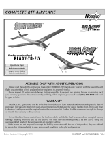
ALMOST-READY-TO-FLY RADIO CONTROLLED MODEL AIRPLANE
Wingspan:68-3/4 in [1745mm] Length:56 in [1420mm]
Wing Area: 722 sq in [46.6 dm
2
]
Weight: 6.25–6.75 lb [2835–3060 g]
Wing Loading: 21 oz/ft
2
[63 g/dm
2
] Radio: 4-5 channel
Engine: .46–.50 cu in [7.5–8.2cc] two-stroke
.52–.56 cu in [8.5–9.2cc] four-stroke
Hobbico
®
guarantees this kit to be free from defects in both
material and workmanship at the date of purchase.This warranty
does not cover any component parts damaged by use or
modification. In no case shall Hobbico’s liability exceed the
original cost of the purchased kit. Further, Hobbico reserves
the right to change or modify this warranty without notice.
In that Hobbico has no control over the final assembly or material
used for final assembly, no liability shall be assumed nor accepted
for any damage resulting from the use by the user of the final
user-assembled product. By the act of using the user-assembled
product, the user accepts all resulting liability.
If the buyer is not prepared to accept the liability associated
with the use of this product, the buyer is advised to return
this kit immediately in new and unused condition to the place
of purchase.
To make a warranty claim, send
the defective part or item to
Hobby Services at this address.
Include a letter stating your name, return shipping address, as
much contact information as possible (daytime telephone number,
fax number, e-mail address), a detailed description of the problem
and a photocopy of the purchase receipt. Upon receipt of the
package the problem will be evaluated as quickly as possible.
WARRANTY
Hobby Services
3002 N. Apollo Dr. Suite 1
Champaign IL 61822
USA

INTRODUCTION . . . . . . . . . . . . . . . . . . . . . . . . . . . . . . 2
AMA . . . . . . . . . . . . . . . . . . . . . . . . . . . . . . . . . . . . . . . 2
SAFETY PRECAUTIONS . . . . . . . . . . . . . . . . . . . . . . . 3
DECISIONS YOU MUST MAKE. . . . . . . . . . . . . . . . . . . 3
Radio Equipment. . . . . . . . . . . . . . . . . . . . . . . . . . . . . . 3
Engine Recommendations . . . . . . . . . . . . . . . . . . . . . . . 3
ADDITIONAL ITEMS REQUIRED . . . . . . . . . . . . . . . . . 4
Hardware and Accessories. . . . . . . . . . . . . . . . . . . . . 4
Building Supplies . . . . . . . . . . . . . . . . . . . . . . . . . . . . 4
Optional Supplies and Tools . . . . . . . . . . . . . . . . . . . . 4
IMPORTANT BUILDING NOTES . . . . . . . . . . . . . . . . . . 4
KIT INSPECTION . . . . . . . . . . . . . . . . . . . . . . . . . . . . . 5
ORDERING REPLACEMENT PARTS . . . . . . . . . . . . . . 6
ASSEMBLY. . . . . . . . . . . . . . . . . . . . . . . . . . . . . . . . . . 9
Assemble the Wing. . . . . . . . . . . . . . . . . . . . . . . . . . . 9
Install the Engine . . . . . . . . . . . . . . . . . . . . . . . . . . . 11
Alternate Engine Installation . . . . . . . . . . . . . . . . . . . 13
Landing Gear Installation . . . . . . . . . . . . . . . . . . . . . 14
Install the Tail Surfaces. . . . . . . . . . . . . . . . . . . . . . . 16
Radio Installation . . . . . . . . . . . . . . . . . . . . . . . . . . . 17
GET THE MODEL READY TO FLY . . . . . . . . . . . . . . . 20
Charge the Batteries. . . . . . . . . . . . . . . . . . . . . . . . . 20
Check the Control Directions . . . . . . . . . . . . . . . . . . 20
Check the Control Throws. . . . . . . . . . . . . . . . . . . . . 21
Adjust the Throttle . . . . . . . . . . . . . . . . . . . . . . . . . . 21
Balance the Model . . . . . . . . . . . . . . . . . . . . . . . . . . 22
Identify Your Model . . . . . . . . . . . . . . . . . . . . . . . . . . 22
AMA SAFETY CODE . . . . . . . . . . . . . . . . . . . . . . . . . 23
ENGINE SAFETY PRECAUTIONS . . . . . . . . . . . . . . . 23
CHECK LIST. . . . . . . . . . . . . . . . . . . . . . . . . . . . . . . . 24
FINAL PREPARATIONS . . . . . . . . . . . . . . . . . . . . . . . 24
Gather Your Tools . . . . . . . . . . . . . . . . . . . . . . . . . . . 24
At the Shop Checklist . . . . . . . . . . . . . . . . . . . . . . . . 24
Flight Preparation. . . . . . . . . . . . . . . . . . . . . . . . . . . 25
Check the Frequency . . . . . . . . . . . . . . . . . . . . . . . . 25
Check the Controls. . . . . . . . . . . . . . . . . . . . . . . . . . 25
Range Check the Radio . . . . . . . . . . . . . . . . . . . . . . 25
Fueling the Nexstar ARF. . . . . . . . . . . . . . . . . . . . . . 25
FLYING . . . . . . . . . . . . . . . . . . . . . . . . . . . . . . . . . . . . 26
Taxiing . . . . . . . . . . . . . . . . . . . . . . . . . . . . . . . . . . . 26
Takeoff . . . . . . . . . . . . . . . . . . . . . . . . . . . . . . . . . . . 26
Flight . . . . . . . . . . . . . . . . . . . . . . . . . . . . . . . . . . . . 26
Landing . . . . . . . . . . . . . . . . . . . . . . . . . . . . . . . . . . 26
MAINTENANCE TIPS . . . . . . . . . . . . . . . . . . . . . . . . . 27
AFTER YOU MASTER THE NEXSTAR ARF . . . . . . . . 27
Removing the SpeedBrakes Training Flaps . . . . . . . . 27
Removing the SpinControl Airfoil Extensions. . . . . . . 27
Installing Dual Aileron Servos. . . . . . . . . . . . . . . . . . 27
NEXSTAR SELECT ARF FAQs. . . . . . . . . . . . . . . . . . 30
FIN SKETCH. . . . . . . . . . . . . . . . . . . . . . . . . . . . . . . . 31
Congratulations and thank you for purchasing a Hobbico
NexSTAR ARF, the next generation in Radio Control
Trainers.You have made the right decision by purchasing a
“real” model airplane with the latest in aerodynamic and
assembly technologies. Once assembled and set up, the
NexSTAR will give you many hours of relaxing easy flying.
Under the guidance of an experienced flight instructor, all
you have to do is to concentrate on learning to fly. And after
you have mastered the NexSTAR, your engine and radio
may be transferred to your next model.
For the latest technical updates or manual corrections to the
Hobbico NexSTAR ARF, visit the Hobbico web site at
www.hobbico.com.
Open the “Airplanes” link, and then
select the Hobbico NexSTAR ARF. If there is new technical
information or changes to this model a “tech notice” box will
appear in the upper left corner of the page.
We urge you to join the AMA (Academy of Model
Aeronautics) and a local R/C club. The AMA is the
governing body of model aviation and membership is
required to fly at AMA clubs. Though joining the AMA
provides many benefits, one of the primary reasons to join
is liability protection. Coverage is not limited to flying at
contests or on the club field.It even applies to flying at public
demonstrations and air shows. Failure to comply with the
Safety Code (excerpts printed in the back of the manual)
may endanger insurance coverage. Additionally, training
programs and instructors are available at AMA club sites to
help you get started the right way. There are over 2,500
AMA chartered clubs across the country. Contact the AMA
at the address or toll-free phone number below:
Academy of Model Aeronautics
5151 East Memorial Drive
Muncie, IN 47302-9252
Tele. (800) 435-9262
Fax (765) 741-0057
Or via the Internet at: http://www.modelaircraft.org
IMPORTANT!!!
Two of the most important things you can do to preserve the
radio controlled aircraft hobby are to avoid flying near full-
scale aircraft and avoid flying near or over groups of people.
AMA
INTRODUCTION
TABLE OF CONTENTS
2

1. Your Hobbico NexSTAR ARF should not be considered a
toy, but rather a sophisticated, working model that functions
very much like a full-size airplane. Because of its
performance capabilities, the Hobbico NexSTAR ARF, if not
assembled and operated correctly, could possibly cause
injury to yourself or spectators and damage to property.
2. You must assemble the model according to the
instructions. Do not alter or modify the model, as doing so
may result in an unsafe or unflyable model. In a few cases
the instructions may differ slightly from the photos. In those
instances the written instructions should be considered as
correct.
3. You must take time to build straight, true and strong.
4. You must use an R/C radio system that is in first-class
condition, and a correctly sized engine and components
(fuel tank, wheels, etc.) throughout the building process.
5. You must correctly install all R/C and other components
so that the model operates correctly on the ground and in
the air.
6. You must check the operation of the model before every
flight to insure that all equipment is operating and that the
model has remained structurally sound. Be sure to check
clevises or other connectors often and replace them if they
show any signs of wear or fatigue.
7. If you are not an experienced pilot or have not flown this
type of model before, we recommend that you get the
assistance of an experienced pilot in your R/C club for your
first flights.If you’re not a member of a club, your local hobby
shop has information about clubs in your area whose
membership includes experienced pilots.
Remember: Take your time and follow the instructions to
end up with a well-built model that is straight and true.
This is a partial list of items required to finish the Hobbico
NexSTAR ARF that may require planning or decision
making before starting to build.Order numbers are provided
in parentheses.
There are four different ways you can set up your NexSTAR.
The “standard,” most economical setup would be to use four
servos - three servos in the fuselage (for the throttle, rudder
and elevator) and one servo in the wing for the ailerons.This
requires only a standard, 4-channel radio. The second
option would be to use two servos in the wing (one for each
aileron). Using two aileron servos will increase the roll rate
(for when you are ready to graduate to slightly more
advanced aerobatics).This option will require a Y-harness to
connect the servos, but a standard 4-channel radio may still
be used. The third option would be to “mix” the two aileron
servos electronically so the ailerons can be operated as
both ailerons and flaps (flaperons).Doubling the ailerons as
flaps adds another dimension to your flying regimen as you
will be able to execute super-slow landings and flight. The
use of flaperons will require a minimum 5-channel computer
radio for mixing the servos electronically. The fifth option is
for those who have a 5-channel, non-computer radio, but
still desire functional flaps.This will require a sixth servo to
operate the flaps separately. Instructions are provided on
how to cut the ailerons so the inboard portion can be
operated as flaps. All of these options may be done with
standard servos and the regular 500mAh-600mAh battery
pack that came with your radio (special servos or a larger
battery pack are not required).
The recommended engine size range for the Hobbico
NexSTAR ARF is .46 to .50 two-stroke or .52 to .56 four-stroke.
If an engine in the upper end of the size range is used,
remember that this is a model that is intended to fly at scale-
like speeds, so throttle management should be practiced. Any
engine in the lower range will be able to fly this model with
authority. Therefore, the engines in the high range are only
recommended for modelers who fly at high altitude.
Engine Recommendations
Radio Equipment
DECISIONS YOU MUST MAKE
NOTE:We, as the kit manufacturer, provide you with a top quality
kit and great instructions, but ultimately the quality of your
finished model depends on how you build it;therefore, we cannot
in any way guarantee the performance of your completed model,
and no representations are expressed or implied as to the
performance or safety of your completed model.
PROTECT YOUR MODEL,YOURSELF
& OTHERS...FOLLOW THESE
IMPORTANT SAFETY PRECAUTIONS
3

4
In addition to the items listed in the “Decisions You Must
Make” section, the following is a list of hardware and
accessories required to finish the Hobbico NexSTAR ARF.
Order numbers are provided in parentheses.
❏ 6" [150mm] Servo extension (HCAM2701 for Futaba
®
)
❏ R/C foam rubber (1/4" HCAQ1000, or 1/2" HCAQ1050)
❏ 3/4" to 1" [19 to 25mm] Heavy duty transparent tape
❏ Hook & loop material (1" x 6" [25 x 150mm] GPMQ4480)
❏ Stick-on segmented lead weights (GPMQ4485)
If you decide to install two aileron servos in your wing connected
to the same channel, you will also need the following:
❏ 1 additional standard servo (for a total of 5)
❏ Y-harness (HCAM2751 for Futaba)
❏ 12" [300mm] servo extension (HCAM2711 for Futaba)
❏ 2 Control horns
❏ 4 2-56 x 3/4" screws
❏ 2 Nylon clevises
❏ 2 Nylon faslinks
❏ 2 Silicone retainers
❏ 2 2-56 x 6" pushrods
If you decide to install two aileron servos in your wing
connected to different channels for flaperons, you will need:
❏ 1 additional standard servo for a total of 5
❏ 5-channel computer radio
❏ (2) 12" [300mm] servo extension (HCAM2711 for Futaba)
❏ 6" [150mm] servo extension (HCAM2701 for Futaba)
❏ 2 Control horns
❏ 4 2-56 x 3/4" screws
❏ 2 Nylon clevises
❏ 2 Nylon faslinks
❏ 2 Silicone retainers ❏ 2 2-56 x 6" pushrods
If you decide to install two aileron servos and one flap servo
in your wing, you will need:
❏ All materials listed in one of the options above
❏ 1 additional standard servo for a total of 6
❏ 6" [150mm] servo extension (HCAM2701 for Futaba)
❏ 2 Nylon clevises ❏ 2 Nylon faslinks
❏ 2 Silicone retainers ❏ 2 2-56 x 6" pushrods
In addition to common household tools and hobby tools, this
is the “short list” of the most important items required to
build the Hobbico NexSTAR ARF.
❏ #1 Hobby knife (HCAR0105)
❏ #11 blades (5-pack, HCAR0211)
❏ 3/4" to 1" [19mm to 25mm] Heavy duty transparent tape.
❏ Threadlocker thread locking cement (GPMR6060)
❏ Small metal file (TAMR4046)
Here is a list of optional tools mentioned in the manual that
will help you build the Hobbico NexSTAR ARF.
❏ Top Flite
®
MonoKote
®
sealing iron (TOPR2100)
❏ Pliers with wire cutter (HCAR0630)
❏ Switch & Charge Jack Mounting Set (GPMM1000)
❏ Servo horn drill (HCAR0698)
❏ AccuThrow
™
Deflection Gauge (GPMR2405)
❏ CG Machine
™
(GPMR2400)
❏ Precision Magnetic Prop Balancer
™
(TOPQ5700)
There are two types of screws used in this kit:
Socket Head Cap screws are designated by a number and
a length.
For example #6 x 3/4"
This is a number six screw that is 3/4" long.
Machine screws are designated by a number, threads per
inch, and a length.
For example 4-40 x 3/4"
This is a number four screw that is 3/4" long with forty
threads per inch
.
·
Photos and sketches are placed before the step they
refer to. Frequently you can study photos in following
steps to get another view of the same parts.
·
SHCS is the abbreviation for Socket Head Cap Screw
which is a machine screw with a socket head.
·
The stabilizer and wing incidences and engine thrust
angles have been factory-built into this model. However,
some technically-minded modelers may wish to check
these measurements anyway. To view this information
visit the web site at www.hobbico.com and click on
“Technical Data.” Due to manufacturing tolerances which
will have little or no effect on the way your model will fly,
please expect slight deviations between your model and
the published values.
·
To convert inches to millimeters, multiply inches by
25.4 (25.4mm = 1")
IMPORTANT BUILDING NOTES
Optional Supplies & Tools
Building Supplies
Hardware & Accessories
ADDITIONAL ITEMS REQUIRED

Before starting to build, take an inventory of this kit to make sure it is complete, and inspect the parts to make sure they
are of acceptable quality. If any parts are missing or are not of acceptable quality, or if you need assistance with assembly,
contact Product Support.When reporting defective or missing parts, use the part names exactly as they are written in the
Kit Contents list.
Great Planes Product Support Telephone: (217) 398-8970, ext. 5
3002 N Apollo Drive, Suite 1 Fax: (217) 398-7721
KIT INSPECTION
5
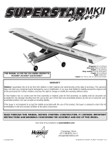
Parts photographed
1. Fuselage
2.Wings
3.Wheels
4. Engine mount
5. 2mm Control rods
6.Wing joiner rods
7. IsoSmooth engine mount
8. 11" x 5" [280 x 127mm] NexSTAR nylon propeller
9. Assembled fuel tank
10. 2-1/2" [64mm] Spinner
11. Nose landing gear
12. 1/4-20 x 2" [51mm] Nylon wing bolt
13. EasyAlign tail bolts
14. CenterCore wing Joiner
15. Fin/Rudder
16. Aluminum main landing gear
17. Stab/elevator
18. SpeedBrakes training flaps
19. Leading Edge Airfoil Extensions
Parts not photographed
4 Nylon clevis
4 Nylon Faslinks
4 Silicone retainers
2 Nylon Aileron Control Horns
4 #4 x 3/4" [19mm] Wood screws
6 #4 x 5/16" [8mm] Machine screws
4 4mm x 3/4" [19mm] Machine screws
4 4mm x 1-1/8" [30mm] Machine screws
4 4mm Nuts
4 4mm Washers
4 4mm Lock washers
2 Nylon control horns
4 #2 x 1/2" [12mm] Wood screws
2 Screw-lock pushrod connector
1
2
3
4
6
5 7
8
9 10 11 12
16
13
14
15
19
18
17

Replacement parts for the Hobbico NexSTAR ARF are
available using the order numbers in the Replacement Parts
List that follows.The fastest, most economical service can be
provided by your hobby dealer or mail-order company.
To locate a hobby dealer, visit the Hobbico web site at
www.hobbico.com. Choose “Where to Buy” at the bottom
of the menu on the left side of the page. Follow the
instructions provided on the page to locate a U.S., Canadian
or International dealer. If a hobby shop is not available,
replacement parts may also be ordered from Tower
Hobbies
®
at www.towerhobbies.com, or by calling toll free
(800) 637-6050.
Parts may also be ordered directly from Hobby Services by
calling (217) 398-0007, or via facsimile at (217) 398-7721,
but full retail prices and shipping and handling charges will
apply. Illinois and Nevada residents will also be charged
sales tax. If ordering via fax, include a Visa
®
or MasterCard
®
number and expiration date for payment.
Mail parts orders and payments by personal check to:
Hobby Services
3002 N Apollo Drive, Suite 1
Champaign IL 61822
Be certain to specify the order number exactly as listed in
the Replacement Parts List. Payment by credit card or
personal check only; no C.O.D.
If additional assistance is required for any reason contact
Product Support by e-mail at:
or by telephone at (217) 398-8970.
REPLACEMENT PARTS LIST
Order
Number Description How to purchase
HCAA3736 . . Wing kit . . . . . . . . . . . .Local hobby dealer
HCAA3737 . . Spin-Control Airfoil
Extensions/Speed
Brakes . . . . . . . . . . . . .Local hobby dealer
HCAA3738 . . Fuselage kit
w/o engine mount . . . .Local hobby dealer
HCAA3739 . . Engine mount . . . . . . .Local hobby dealer
HCAA3740 . . IsoSmooth
engine mount . . . . . . . .Local hobby dealer
HCAA3741 . . Tail set . . . . . . . . . . . . .Local hobby dealer
HCAA3742 . . Landing gear . . . . . . . .Local hobby dealer
HCAA3743 . . Decal set . . . . . . . . . . .Local hobby dealer
HCAA3744 . . NexSTAR nylon
11 x 5 prop . . . . . . . . .Local hobby dealer
Missing pieces . .Contact Product Support
Instruction manualContact Product Support
Full-size plans . . . . . . . . . . . .Not available
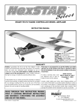
This new mount may look like other aluminum engine
mounts, but make no mistake, it is unique. The engine
mounting lugs are installed in rubber boots that absorb
engine vibration to protect your airframe and radio
components, increasing their life span. The IsoSmooth
engine mount works so well that you should check your
propeller for nicks or cracks, because with this mount, you
won't feel a thing.
The NexSTAR ARF is equipped with a high speed needle
valve extender/limiter to make engine adjustments safer
and easier.The extender/limiter has been set at the factory
to limit the movement of the high speed needle so that it
cannot be adjusted out of the optimum range.This way the
engine will always work at its peak performance without the
worry of engine damage. The extender/limiter will allow the
needle to be set from the leanest desired setting for safe
operation (fully clockwise) to the richest desired setting for
break in (fully counterclockwise).
Extender/Limiter
IsoSmooth
™
Engine Mount
ORDERING REPLACEMENT PARTS
6

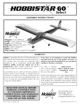
The wings of most trainers are mounted with rubber bands.
This allows for some flexibility in case of a hard landing.
Rubber bands work well, but they are just plain ugly and a
mess. The PivotFlex Wing Mounting System combines the
looks of a bolt-on system with the flexibility of rubber bands.
The new system allows the wing to move under sudden
loads (such as a wing tip hitting the ground) and will release
the wing from the airplane under extreme loads such as a
crash—all that while looking great.
The EasyAlign Tail Mounting System aligns the stabilizer
with the fuselage and fin while tightening the tail bolts.The
tail bolts slide into blocks in the fuselage under the
stabilizer. As the tail bolts are tightened, both the fin and
stab are aligned and secured while strengthening the aft
area of the fuselage.No tools are necessary for installation.
To speed and simplify assembly, the Hobbico NexSTAR
ARF comes equipped with the SnapGear Landing Gear.
This new gear offers effortless and tool less main landing
gear installation. It takes only a few seconds to install the
landing gear and it can also be removed from the fuselage
in seconds.
The Hobbico NexSTAR ARF uses a three-line fuel line
system to simplify fueling and de-fueling.
Three-Line Fuel System
SnapGear
™
Landing Gear
EasyAlign
™
Tail Mounting System
PivotFlex
™
Wing Mounting System
7

The CenterCore wing rib is a nylon part that comes
preinstalled onto one of the wing halves. It performs several
functions: it aligns the two wing halves; it is a mount for the
aileron servo;the incorporated wing dowel holds the wing in
place; and it holds and aligns the wing bolt to the PivotFlex
™
Wing Mounting System. Joining the wing halves and wing
installation on the fuselage has never been easier.
These are the extensions that are installed at the leading
edge near the tips of the wings. These extensions were
developed by NASA (National Aeronautics and Space
Administration) to help light airplanes prevent stalls and
spins during landing approaches. That is exactly what they
do for your NexSTAR ARF. They slow down the airplane,
increase its stall resistance and prevent it from spinning, all
desired characteristics of a trainer airplane. The wing
extensions can be removed after you become proficient with
the NexSTAR ARF, for faster, more aerobatic performance.
The SpeedBrakes Training Flaps were designed to allow your
NexSTAR ARF to fly slower, reduce top speed and shorten
the landing approach. Thanks to these flaps, your NexSTAR
ARF will bleed off speed quickly when the throttle is reduced
so that long landing approaches are not necessary.
Additionally, the top speed is considerably reduced to make
the airplane easier to handle. These SpeedBrakes can also
be removed after acquiring some experience with the
airplane for faster, more aerobatic performance.
SpeedBrakes
™
Training Flaps
SpinControl
™
Airfoil Extensions
CenterCore
™
Wing Rib
8

For this section you will need:
Note: The following steps show the assembly of the wing
using one aileron servo. For a 2-servo installation, please
refer to the section “After You Master the NexSTAR in its
Original Form” on page 27.
❏ 1.Mark a line on the bottom of the wings 1/4" [6mm] from
the end of the tips.
❏ 2. Install the Airfoil Extensions on both wings as shown
using 3/4" to 1" [19 to 25mm] heavy duty clear plastic tape.
❏ 3. Locate the Spin-Control Airfoil Extension decals on the
decal sheet and apply them to both wings following the
scheme on the top of both wings. Also apply the NexSTAR
decal on the top of the left or right wing.
❏ 4. Install the CenterCore wing rib on the right wing using
two #4 x 3/4" [19mm] screws.
❏ 5. Install the aileron servo as shown using the hardware
supplied by the manufacturer.
1 Left wing
1 Right wing
2 Airfoil extensions
2 SpeedBrakes training
flaps
1 CenterCore wing rib
1 Steel wing rod
1 Anti-Rotation steel pin
2 Nylon clevises
2 Nylon faslinks
2 Silicone retainers
2 2-56 X 6" [150mm]
pushrods
2 Nylon horns
4 #4 x 3/4" [19mm]
Wood screws
6 #4 x 5/16" [8mm]
Wood screws
1 Standard servo
1 Phillips screwdriver
3/4" to 1" [19 to
25mm] Heavy duty
clear plastic tape
Assemble the Wing
ASSEMBLY
9

❏ 6. Install the wing rod and the anti-rotation pin into the
right wing.
❏ 7.Carefully slide the left wing all the way onto the rod and
into the CenterCore wing rib until it stops.
❏ 8. Use two more #4 x 3/4" [19mm] screws to hold the two
wing halves together.
❏ 9. Cut and bend a 2mm x 6"[150mm] pushrod to match
the sketch above. Make a left and a right pushrod.
❏ 10. Cut a servo arm as shown above and use a Hobbico
Servo Horn Drill (or a #48 or 5/64" [2mm] drill bit) to enlarge
the servo arm holes. Install the arm on the servo. Install a
clevis and a clevis retainer on the threaded end of the
pushrods.Slide the unthreaded end of the pushrod into your
servo arms and install Faslinks to secure them.
10

❏ 11. Install the nylon horns on the aileron torque rods.
Thread them in until the bottom of the horn is about 1/2"
[12mm] from the wing surface. Connect the clevises to the
horns. Slip the clevis retainers over the clevises.
❏ 12. Locate one of the SpeedBrakes Training flaps.There
are three small holes drilled into the trailing edge of the wing
near the center. Install the flap to the wing using three #4 x
1/4" [6mm] screws. The inner end of the flap should align
with the end of the aileron.
❏ 13. Install the other flap onto the other wing using three
more #4 x 1/4" [6mm] screws. The wing is now complete.
Note: Install the leading edge extensions and the flaps
for your initial flights. The airplane has been designed
around them and it performs better as a trainer with them
installed. Never attempt to fly the airplane for the first time
without them or with just one of the devices as the model will
be difficult to trim.Do not let anyone’s opinion get in the way.
Install both these devices for your initial flights. If after
a few flights you decide to remove the extensions or flaps,
then read the section “After You Master the NexSTAR in its
Original Form” on page 27.
For this section you will need:
❏ 1. Slide the fuel tank into the fuel tank compartment.
Make sure the fuel tubing comes out through the hole in the
firewall. Slide the fuel tank in until the neck of the fuel tank
comes out the firewall as shown above. Use a Phillips
screwdriver to tighten the fuel tank screw and secure the
tank in place.
❏ 2. Use four 4mm x 20mm machine screws and four 4mm
washers to install the engine mount as shown above. Use
Great Planes Thread Locking Compound on the machine
screws before you tighten them.
Engine
Fuel tank
Metal engine mount
4 4mm x 20mm Engine
mount machine
screws
IsoSmooth complete
engine mount
4 4mm x 30mm
IsoSmooth engine
mount screws
4 4mm Nuts
8 4mm Washers
4 4mm Lock washers
2-56 x 17-1/2"
[445mm] pushrod.
Phillips screwdriver
Install the Engine
11

❏ 3. Install the IsoSmooth rubber boots on the engine
mounting lugs. The IsoSmooth rubber boots have been
designed to fit most .46 size engines. If the boots do not fit
your engine, then you will have to use an alternate method
to install your engine (see below).
❏ 4. Use four 4mm x 30mm machine screws, four 4mm
washers, four 4mm lock washers and four 4mm nuts to secure
the engine with the IsoSmooth nylon bracket on the engine
mount. Use Great Planes Thread Locking Compound on the
screws to prevent them from coming loose with vibration.
❏ 5. Install a clevis and a clevis retainer on the threaded
end of the 17-1/2" [445mm] pushrod. Bend the pushrod
slightly as shown above to clear the engine mounting bolts.
❏ 6.Slide the pushrod into the guide tube and then connect
the clevis to the carburetor arm as shown above. Slip the
clevis retainer onto the clevis.
❏ 7. Mount the muffler on the engine following your engine
manufacturer’s recommendations.Also, install the glow plug
and connect the fuel lines to the engine.The red line goes
to the pressure tap on the muffler, the green line goes to the
needle valve, and the blue line is the fill line. Cap the fill line
with the aluminum plug supplied.
12

❏ 8. Install the spinner backplate, propeller, propeller
washer and propeller nut to the engine. Align the propeller
with the marks on the spinner backplate and then tighten
the propeller nut securely.
❏ 9. Fit the spinner cone to the back plate. Then, use a
Phillips screwdriver to tighten the spinner screws snugly, but
not over-tight.
Selecting the correct propeller for an
airplane is very important. Your
NexSTAR ARF comes equipped with
a specially-designed nylon 11x5
propeller (HCAA3744) with painted
tips. The painted tips are a safety
feature that will help you see the
propeller arc as the engine is running.
Propeller (HCAA3744)
Keep away from the propeller while the engine is running.
The engine size used on the NexSTAR ARF is powerful
enough to cause damage if anything (including you) gets in
the propeller arc.The propeller is made out of flexible nylon
so that it won’t break on light contact with the runway or
weeds. If the propeller ever gets in contact with anything
while the engine is running, inspect it before running it
again. Check for cracks, scuffled tips or unbalanced blades.
If necessary, replace the propeller. The Hobbico NexSTAR
ARF was designed around an 11x5 propeller for best
performance. The 11x5 propeller helps keep the airplane
speed down at full throttle; it increases takeoff performance
on any surface, including tall grass; and it acts as a brake
when the nose is pointed down. Should you ever need to
replace the propeller, replace it with the same or similar
11x5 propeller.There is no benefit to using a larger propeller
or one with more pitch.
Carefully balance your propeller and spare propellers
before you fly. An unbalanced prop can be the single most
significant cause of vibration that can damage your model.
We use a Top Flite Precision Magnetic Prop Balancer
™
(TOPQ5700) in the workshop and keep a Great Planes
Fingertip Prop Balancer (GPMQ5000) in our flight box.
Your engine is now installed.
❏ 1. If the engine rubber boots do not fit the engine of your
choice, you will have to install the engine as shown above
using two metal straps (included), four 4mm x 30mm, four
4mm nuts, four 4mm washers and four 4mm lock washers.
Alternate Engine Installation
13

For this section you will need:
❏ 1. File two flat spots on the nose gear wire as shown above.
❏ 2. Install the nylon nose gear bracket to the firewall using
two 4 x 20mm machine screws and two 4mm flat washers.
Use Great Planes Thread Locking Compound on the
machine screws before tightening them.
❏ 3. Place a wheel collar in the nylon steering arm as
shown.Use the 4 x 6mm [1/4"] machine screw on the wheel
collar. Slide the steering pushrod’s “Z” bend through the
hole in the steering arm.
❏ 4. Slide the steering arm’s pushrod into its guide tube.
Install the nose landing gear leg through the nylon bracket,
the steering arm and then the engine mount. Tighten the
screw on the steering arm.
❏ 5. Install the nose wheel on the nose gear wire. Use two
wheel collars, one on each side of the wheel, to align it and
secure it in place.Apply some Great Planes Thread Locking
Compound to the screws.
❏ 6. Install a wheel axle on each aluminum landing gear
leg. File a flat spot near the end of the axle.
❏ 7. Install a wheel on each of the axles and then secure
them with a wheel collar. Use some Great Planes Thread
Locking Compound on the screws.
Nose gear wire
Aluminum main gear
(2 parts)
3 Wheels
2 Landing gear axles
1 Nylon nose gear
bracket
2 4mm x 19mm
Machine screws
2 4mm Washers
1 Steering arm
5 4mm Wheel collars
1 Steering pushrod
Phillips screwdriver
Metal file
Landing Gear Installation
14

❏ 8.Slide one of the main landing gear legs into the landing
gear slot as shown above. Push it in until you hear a “click”
or until it does not slide in any more. Note:The two landing
gear legs are identical, so it does not matter which one you
install on the left side or right side of the airplane.
❏ 9. Install the other landing gear leg on the other side of
the fuselage the same way. Once they are both installed,
apply a light force to pull them out.You should not be able
to pull them out. If they do pull out, then push them back in
again until they are secured properly. Note:The legs may fit
a little loose inside the pocket.This is normal as long as you
are not able to pull the landing gear legs out.
Landing gear installation is complete.
Note: Should you ever need to remove the landing gear
from the fuselage, insert a screwdriver into the hole under
the fuselage farther from the leg you want to remove.Apply
light pressure to the tab inside the hole and pull the landing
gear leg out. Once the tab is moved, the screwdriver must
be removed to allow the leg to come all the way out. Do the
same with the other landing gear leg.
Note: If your landing gear does not insert easily in the
fuselage or it does not lock in, clean up any glue or paint
blobs that may be on the gear or in the mounting
mechanism. Insert the gear again and make sure it does
lock in.
Note: If your landing gear legs spread after a hard landing,
remove the legs from the airplane and bend them back to
the correct position with a vise. Do not try to straighten the
legs while installed in the airplane as that may damage the
Snap Gear Landing Gear mechanism.
15

For this section you will need:
Note: It is recommended that you apply the fuselage, stab
and fin decals at this point. It is easier to do when the parts
are all apart.
❏ 1. Install a nylon clevis and a clevis retainer on the two
steel pushrods.Slide both pushrods into their guide tubes in
the tail of the airplane.
❏ 2. Position a nylon control horn on the bottom of the right
elevator all the way against its inner edge.Mark the location
of the control horn mounting holes. Drill through the marks
with a 1/16" [1.6mm] drill bit. Secure the control horn to the
elevator using two #2 x 1/2" [12mm] screws.
❏ 3. Position a nylon control horn on the rudder as shown
about 1/8" [3mm] from the bottom edge.Note that one of the
edges of the control horn is aligned with the hinge line of the
rudder. Mark the location of the control horn mounting
holes. Drill through the marks with a 1/16" [1.6mm] drill bit.
Secure the control horn to the rudder using two #2 x 1/2"
[12mm] screws.
❏ 4. Insert the horizontal stabilizer into the stab slot as
shown above.Insert the two nylon fin tail bolts half-way into
the bottom fuselage and into the stab to hold it in place.
❏ 5. Place the fin over the sketch found on the last page of
the manual and make sure the fin rods are bent at the same
angle as the ones shown on the sketch.This step is critical
to make the fin installation easier.
Stabilizer
Fin
2 Control horns
4 #2 x 1/2 [12mm]
Screws
2 Nylon tail bolts
2 Nylon clevises
2 Silicone clevis
retainers
2 2mm Steel pushrods
Phillips screwdriver
Install the Tail Surfaces
16

❏ 6. Insert the vertical stabilizer into the fin slot as shown
above. During installation, make sure the rudder control
horn is below the elevator so that it does not interfere.It may
take a little maneuvering to slide the aft fin rod in front of the
wood block in the fuselage slot.
❏ 7.Tighten the bolts until they fit snugly against the bottom
of the fuselage. Note: Over tightening these bolts will
damage the nylon threads and may cause in flight failure.
Do not over tighten these bolts.
❏ 5.Connect both the elevator and rudder pushrod clevises
to their control horns.Use the second hole from the outer tip
of the control horn for both of them. This will allow you to
obtain the recommended throws. Slide the silicone clevis
keeper over the clevis.
Tail assembly is complete.
For this section you will need:
❏ 1. Install the elevator, rudder and throttle servos in the
fuselage servo tray as shown above using the hardware
supplied by the radio manufacturer.
3 Standard size servos
1 6" [150mm] Extension
servo mounting
Hardware
2 Faslinks
2 Complete screw-lock
pushrod connectors
Foam sheet
Pliers
Phillips screwdriver
Radio Installation
17

❏ 2. Wrap the receiver and the battery with foam and then
install them on the radio tray. Use the hook and loop
material supplied to secure them in place.
❏ 3. Install a 6" [150mm] extension on the receiver’s aileron
channel. Connect the radio switch to the receiver and the
battery.Use heat shrink tubing to secure the battery connection.
Install the radio tray in the fuselage with two #4 x 3/8" [9mm]
wood screws.Connect all the servos to the receiver.
❏ 4.Install the radio switch to the fuselage on the opposite side
of the muffler. If you desire, you can also install a charge jack.
This will allow you to charge the batteries or check their voltage
at the field without taking off the wing.In the instruction manual
airplane we installed an Ernst charge jack.
❏ 5. Route the receiver antenna under the servo tray. Install
a retainer on it and then slip it through the plastic guide tube
in the middle until it exits at the aft end of the airplane.
Secure the antenna with tape. Turn on the transmitter and
then the receiver and center all the trims on the transmitter.
❏ 6. Cut the elevator, throttle and the rudder servo arms as
shown. Install a Screw-Lock Pushrod Connector on the throttle
and the rudder arm as shown above. Note the holes where the
Screw-Lock Pushrod Connectors are connected.
18

❏ 7. Slide the steering pushrod and the throttle pushrod
through the Screw-Lock Pushrod Connectors. Install the
servo arms centered on the servos and center the rudder
and elevators.
❏ 8. Mark the elevator and rudder pushrods where they
meet with the servo arm holes. Bend the pushrods 90
degrees up at the mark.Enlarge the servo arm holes where
the pushrods will be connected with a Hobbico Servo Horn
Drill (or a #48 or 5/64" [2mm] drill bit.) Slide pushrods into
the servo arms. Note the servo arm holes used to connect
the elevator and rudder pushrod.
❏ 9. Install a Faslink on the elevator and rudder pushrods
to secure them to the servo arms. Cut off the excess wire.
❏ 10. Center the nose wheel and tighten the steering’s
Screw-Lock Pushrod Connector. Move the throttle stick to
full power and then fully open the carburetor by pushing on
the throttle pushrod. Make sure the throttle servo is working
in the correct direction and reverse it if necessary.Install the
throttle’s servo arm as shown and tighten the Screw-Lock
Pushrod Connector. Cut any excess wire and replace the
servo arm screws.
❏ 11. Remove the aileron servo arm and connect the
aileron servo to the receiver aileron servo extension. Center
the transmitter trims and reinstall the aileron servo arm
making sure it is centered. Replace the servo arm screw.
Use thread locking compound on the screws.
Note: The control surfaces should be centered when the
trims in your transmitter are centered. Minor adjustments
can be made by screwing or unscrewing the nylon clevises
on the control surfaces.
19

Now the plane is assembled, but there are a few things that
must be done before it will be ready to fly.You must carefully
perform all of the following Setup procedures. If possible,
have your flight instructor assist you.
If you have not yet charged the batteries, you may still
proceed. However, as the batteries have not yet been fully
charged, they may not provide enough power to make it all
the way through the setup procedures. If the batteries quit
working, set your tools aside and charge the batteries as
described in the instruction manual for the radio control
system that you are using.
Follow the battery charging instructions that came with your
radio control system to charge the batteries. You should
always charge your transmitter and receiver batteries the
night before you go flying, and at other times as
recommended by the radio manufacturer.
❏ 1. Move the right control stick on the transmitter to the
right as shown in the photo. Observe the direction the
ailerons move.
The right aileron should move up and the left aileron should
move down. Moving the control stick to the left should make
the ailerons move the opposite way. If the ailerons do not
respond as described, reverse the direction using the
reversing switch for the aileron on the face of the
transmitter. If necessary, refer to the instructions in your
radio instruction manual to identify and operate the
reversing switch.
❏ 2.Move the right stick down and observe the direction the
elevator moves.
Moving the right stick down should make the elevator move
up. Note that moving the elevator stick down moves the
elevator up (which, in flight, pushes the tail down, thus
increasing the angle of the wing and making the model
climb).The best way to keep this in mind is to think in terms
of a pilot in an airplane. He pulls the control stick back to
“pull up” the nose of the plane.
Check Control Direction
CAUTION: Unless the instructions that came with your
radio system state differently, the initial charge on new
transmitter and receiver batteries should be done for 15
hours using the slow-charger that came with the radio
system.This will “condition” the batteries so that the next
charge may be done using the fast-charger of your choice.
If the initial charge is done with a fast-charger, the
batteries may not reach their full capacity and you may be
flying with batteries that are only partially charged.
Charge the Batteries
GET THE MODEL READY TO FLY
20
/