Page is loading ...

WARRANTY
Hobbico
®
guarantees this kit to be free from defects in both material and workmanship at the date of purchase. This warranty does
not cover any component parts damaged by use or modification. In no case shall Hobbico’s liability exceed the original cost of
the purchased kit. Further, Hobbico reserves the right to change or modify this warranty without notice.
In that Hobbico has no control over the final assembly or material used for final assembly, no liability shall be assumed nor accepted
for any damage resulting from the use by the user of the final user-assembled product.By the act of using the user-assembled product,
the user accepts all resulting liability.
If the buyer is not prepared to accept the liability associated with the use of this product, the buyer is advised to return this
kit immediately in new and unused condition to the place of purchase.
To make a warranty claim send the defective part or item to Hobby Services at the address below:
Hobby Services
3002 N. Apollo Dr. Suite 1
Champaign IL 61822
USA
Include a letter stating your name, return shipping address, as much contact information as possible (daytime telephone number, fax
number, e-mail address), a detailed description of the problem and a photocopy of the purchase receipt. Upon receipt of the package
the problem will be evaluated as quickly as possible.
READ THROUGH THIS MANUAL BEFORE STARTING
CONSTRUCTION.IT CONTAINS IMPORTANT INSTRUCTIONS
AND WARNINGS CONCERNING THE ASSEMBLY AND
USE OF THIS MODEL.
HCAZ3076 for HCAA2076 V1.0 Entire Contents © Copyright 2004
Champaign, IL
(217) 398-8970
E-mail:
airsupport@hobbico.com
INSTRUCTION MANUAL
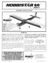
Wingspan: 56 in [1420mm]
Wing Area: 560 sq in [36.1dm
2
]
Weight: 5-5.5 lb [2270 – 2490g]
Wing Loading: 21 – 23 oz/sq ft [64 – 70g/dm
2
]
Length: 40 in [1015mm]
Radio: 4-Channel with five servos
Engine: .15-.25 cu in [2.5-4cc] two-stroke, .26-.40 cu in
[4.5-6.5cc] four-stroke
™

INTRODUCTION................................................................2
AMA ...................................................................................2
SAFETY PRECAUTIONS..................................................2
ADDITIONAL ITEMS REQUIRED.....................................3
Hardware & Accessories .............................................3
Adhesives & Building Supplies....................................3
Covering Tools .............................................................3
Optional Supplies & Tools............................................3
IMPORTANT BUILDING NOTES.......................................3
ORDERING REPLACEMENT PARTS...............................4
METRIC/INCH RULER ......................................................4
KIT CONTENTS.................................................................5
PREPARATIONS................................................................6
BUILDING INSTRUCTIONS..............................................6
Hinge the Control Surfaces..........................................6
Join the Wing Halves...................................................7
Mount the Engines.......................................................8
Assemble & Install the Fuel Tanks...............................9
Mount the Tail.............................................................10
Finish the Wing..........................................................12
Install the Radio Gear................................................15
Install the Landing Gear ............................................16
Mount the Receiver & Battery....................................18
Apply the Decals........................................................18
GET THE MODEL READY TO FLY..................................19
Check the Control Directions.....................................19
Set the Control Throws..............................................19
Balance the Model (C.G.)..........................................19
Balance the Model Laterally......................................20
PREFLIGHT.....................................................................20
Identify Your Model.....................................................20
Charge the Batteries..................................................20
Balance the Propellers...............................................21
Ground Check............................................................21
Range Check.............................................................21
ENGINE SAFETY PRECAUTIONS .................................21
AMA SAFETY CODE (excerpts)....................................21
CHECK LIST....................................................................22
FLYING.............................................................................23
Takeoff .......................................................................23
Flight..........................................................................23
Landing......................................................................23
The Hobbico TwinStar
™
ARF is a fun, exciting sport twin
aircraft. It makes a terrific first twin or “twin trainer” to help
you get ready to fly more true-to-scale and also more
challenging-to-fly twins such as a DC-3, or it simply can be
a really fun twin aircraft for the average sport pilot. ENJOY!
For the latest technical updates or manual corrections to the
TwinStar visit the Hobbico web site at
www.hobbico.com
.Open
the “Airplanes” link, then select the TwinStar ARF.If there is new
technical information or changes to this model a “tech notice”
box will appear in the upper left corner of the page.
We urge you to join the AMA (Academy of Model
Aeronautics) and a local R/C club. The AMA is the
governing body of model aviation and membership is
required to fly at AMA clubs. Though joining the AMA
provides many benefits, one of the primary reasons to join
is liability protection. Coverage is not limited to flying at
contests or on the club field. It even applies to flying at
public demonstrations and air shows.Failure to comply with
the Safety Code (excerpts printed in the back of the
manual) may endanger insurance coverage. Additionally,
training programs and instructors are available at AMA club
sites to help you get started the right way. There are over
2,500 AMA chartered clubs across the country. Contact the
AMA at the address or toll-free phone number below:
IMPORTANT!!! Two of the most important things you can
do to preserve the radio controlled aircraft hobby are to
avoid flying near full-scale aircraft and avoid flying near or
over groups of people.
1.Your TwinStar should not be considered a toy, but rather
a sophisticated, working model that functions very much
like a full-size airplane.If the TwinStar is not assembled and
operated correctly, it could possibly cause injury to you or
spectators and damage to property.
2. You must assemble the model according to the
instructions.Do not alter or modify the model, as doing so may
result in an unsafe or unflyable model. In a few cases the
instructions may differ slightly from the photos. In those
instances the written instructions should be considered correct.
3.You must take time to build straight, true and strong.
PROTECT YOUR MODEL,YOURSELF
& OTHERS...FOLLOW THESE
IMPORTANT SAFETY PRECAUTIONS
Academy of Model Aeronautics
5151 East Memorial Drive
Muncie, IN 47302
Tele: (800) 435-9262
Fax (765) 741-0057
Or via the Internet at:
http://www.modelaircraft.org
AMA
INTRODUCTION
TABLE OF CONTENTS
2

4. You must use an R/C radio system that is in first-class
condition, and a correctly sized engine and components
(fuel tank, wheels, etc.).
5.You must install all R/C and other components so that the
model operates correctly on the ground and in the air.
6.You must check the operation of the model before every
flight to ensure that all equipment is operating and that the
model remains structurally sound.Be sure to check clevises
or other connectors often and replace them if they show any
signs of wear or fatigue.
7. If you are not an experienced pilot or have not flown this
type of model before, we recommend that you get the
assistance of an experienced pilot in your R/C club for your
first flights. If you’re not a member of a club, your local
hobby shop can help you find a club and experienced pilots.
Remember:Take your time and follow the instructions to
end up with a well-built model that is straight and true.
This is the list of hardware and accessories required to
finish the Twinstar ARF. Order numbers are provided
in parenthesis.
❏ Y-harness (HCAM2751 for Futaba
®
)
❏ R/C foam rubber 1/2" [13mm] (HCAQ1050)
❏ 3' [900mm] Standard silicone fuel tubing (GPMQ4131)
❏ 1/2 oz. [15g] Thin Pro CA (GPMR6001)
❏ 1/2 oz. [15g] Medium Pro CA+ (GPMR6007)
❏ Pro 30-minute epoxy (GPMR6047)
❏ Pro 6-minute epoxy (GPMR6045)
❏ Drill bits: 1/16" [1.6mm] and 5/32" [4mm]
❏ 4-40 Tap and drill set (GPMR8101)
❏ Tap handle (GPMR8120)
❏ Stick-on, segmented lead weights (GPMQ4485)
❏ Top Flite
®
MonoKote
®
sealing iron (TOPR2100)
❏ Top Flite Hot Sock
™
iron cover (TOPR2175)
❏ 2 oz. [57g] Spray CA activator (GPMR6035)
❏ CA applicator tips (HCAR3780)
❏ CA debonder (GPMR6039)
❏ Epoxy brushes (6, GPMR8060)
❏ Mixing sticks (50, GPMR8055)
❏ Mixing cups (GPMR8056)
❏ Builder’s Triangle Set (HCAR0480)
❏ Curved-tip canopy scissors for trimming plastic
parts (HCAR0667)
❏ Pliers with wire cutter (HCAR0630)
❏ Robart
®
Super Stand II (ROBP1402)
❏ Masking tape (TOPR8018)
❏ Denatured alcohol (for epoxy clean up)
❏ Dead Center
™
Engine Mount Hole Locator (GPMR8130)
❏ AccuThrow
™
Deflection Gauge (GPMR2405)
❏ CG Machine
™
(GPMR2400)
Descriptions of machine screws include the number of
threads per inch and a length.Example: 4-40 x 3/4" [19mm].
That describes a number four screw that is 3/4" long with
forty threads per inch.
• When you see the term
test fit
in the instructions, it
means that you should first position the part on the
assembly without using any glue. If necessary, modify the
part to ensure the best fit.
• Whenever the term
glue
is written you should rely upon
your experience to decide what type of glue to use.When a
specific type of adhesive works best for that step, the
instructions will make a recommendation.
• Whenever just
epoxy
is specified you may use 6-minute,
30-minute or 45-minute epoxy. When 30-minute epoxy is
specified it is highly recommended that you use only 30-minute
(or 45-minute) epoxy, because you will need the working time
and/or the additional strength.
•
Photos
and
sketches
are placed before the step they
refer to. In many cases, you can get a different look at the
same parts by looking at photos in following steps.
IMPORTANT BUILDING NOTES
Optional Supplies & Tools
Covering Tools
Adhesives & Building Supplies
Hardware & Accessories
ADDITIONAL ITEMS REQUIRED
We, as the kit manufacturer, provide you with a top-
quality, thoroughly tested kit and instructions, but
ultimately the quality and flyability of your finished model
depends on how you build it; therefore, we cannot in any
way guarantee the performance of your completed
model, and no representations are expressed or implied
as to the performance or safety of your completed model.
3

4
E-Replacement parts for the Hobbico TwinStar ARF are available using the order numbers in the Replacement Parts List
that follows.The fastest, most economical service can be provided by your hobby dealer or e-mail order company.
To locate a hobby dealer, visit the Hobbico web site at
www.hobbico.com
. Choose “Where to Buy” at the bottom of the
menu on the left side of the page.Follow the instructions provided on the page to locate a U.S., Canadian or International
dealer. If a hobby shop is not available, replacement parts may also be ordered from Tower Hobbies at
www.towerhobbies.com
, or by calling toll free (800) 637-6050.
Parts may also be ordered directly from Hobby Services by calling (217) 398-0007, or via facsimile at (217) 398-7721, but
full retail prices and shipping and handling charges will apply.Illinois and Nevada residents will also be charged sales tax.
If ordering via fax, include a Visa
®
or MasterCard
®
number and expiration date for payment.
If ordering via mail, send parts orders and payments by personal check to:
Hobby Services
3002 N Apollo Drive, Suite 1
Champaign IL 61822
Be certain to specify the order number exactly as listed in the Replacement Parts List. Payment by credit card or
personal check only; no C.O.D.
If additional assistance is required for any reason, contact Product Support by e-mail at
productsupport@hobbico.com
,
or by telephone at (217) 398-8970.
Replacement Parts List
Order Number Description How to Purchase
Missing pieces.....................Contact Product Support
Instruction manual...............Contact Product Support
HCAA3750 Wing Set
HCAA3751 Fuselage
HCAA3752 Tail Set
HCAA3753 Spinner (2 pcs.)
HCAA3754 Landing Gear
HCAA3755 Nacelle Set (Left & Right)
HCAA3756 Nacelle Cover (2 pcs.)
HCAA3757 Nose Cone
HCAA3758 Fuel Tank
HCAA3759 Decal Set
ORDERING REPLACEMENT PARTS
................
Contact Your Hobby
Supplier to Purchase
These Items
To convert inches to millimeters, multiply inches by 25.4

5
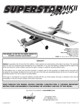
1. Fuselage
2. Fin & Rudder
3. Stabilizer & Elevator
4. Left Wing & Aileron
5. Right Wing & Aileron
6. Hook & Loop Material
7. Wing Joiner (3)
8. Servo Mounts
9. Nose Gear Pushrod Support
10. Wing Bolt Plate
11. Engine Mounts
12. Fuel Tank (2)
13. Right Engine Nacelle
14. Right Nacelle Cover
15. Nose Cone
16. Left Nacelle Cover
17. Left Engine Nacelle
18. Nose Gear
19. Main Landing Gear (2)
20. 2-3/4" [70mm] Wheels (3)
21. Pushrods
Kit Contents (not photographed)
Kit Contents
(2) Large Control Horn
(6) Nylon Clevis
(2) Aileron Torque Rod Horn
(4) 2-56 x 1/2" [13mm] Machine Screw
(6) Nylon FasLink
(1) Screw-Lock Pushrod Connector
(1) Nylon Retainer
(1) 4-40 x 1/4" [6mm] Socket Head Screw
(6) Silicone Retainer
(7) 5/32" [4mm] Wheel Collar
(6) 6-32 Set Screw
(1) 6-32 x 1/4" [6mm] Socket Head
Cap Screw
(1) Nylon Steering Arm
(1) Nylon Nose Gear Mount
(4) 4-40 x 1/2" [13mm] Bolt
(28) #4 Washer
(16) 4-40 x 3/4" [19mm] Socket Head
Cap Screw
(16) #4 Lock Washer
(2) 1/4-20 x 2" [50mm] Nylon Bolt
(1) Landing Gear Strap
(8) #4 x 1/2" [13mm] Screw
(12) #2 x 3/8" [9.5mm] Screw
(12) #2 Washer
Before starting to build, take an inventory of this kit to make sure it is complete, and inspect the parts to make sure they
are of acceptable quality.If any parts are missing or are not of acceptable quality, or if you need assistance with assembly,
contact Product Support.When reporting defective or missing parts, use the part names exactly as they are written in the
Kit Contents list.
Hobbico Product Support
3002 N Apollo Drive, Suite 1
Champaign, IL 61822
Telephone: (217) 398-8970, ext. 5
Fax: (217) 398-7721
E-mail:
airsupport@hobbico.com
KIT CONTENTS
1
2
7
6
3
4
5
8
10
9
11
10
12
13
14
15
16
20
19
21
18
17
11

❏ 1. If you have not yet done so already, remove the major
parts of the kit from the box (wings, fuse, tail parts, etc.) and
inspect them for damage. If any parts are damaged or
missing, contact
Product Support
as listed on page 5.
❏ 2.Remove the masking tape and separate the ailerons from
the wing, the rudder from the fin and the elevator from the stab.
Where necessary, use a covering iron set for low temperature
covering materials, with a covering sock, to tighten any covering
that may have loosened during storage or from removing the
masking tape. Apply pressure over sheeted areas to
thoroughly bond the covering to the wood.
❏ 1. Cut nineteen 3/4" x 1" [19 x 25mm] hinges from the 2"
x 9" [50 x 230mm] CA hinge strip. Snip the corners off so
they go in easier.
❏ 2.Test fit four hinges into the hinge slots of both ailerons
and both wings. If you have difficulty inserting the hinges,
insert a #11 blade into the slot and carefully move it back
and forth to slightly widen the slot.
❏ 3.Test fit the ailerons to the wing with the hinges.
❏ 4. Separate the ailerons from the wing and take out all
the hinges.
❏ 5. Cut a small strip of covering from both sides of each
hinge slot.If this is not done, the covering may interfere with
the penetration of the CA into the slot and the movement of
the aileron.
❏6.Fit the hinges to the ailerons.Be sure that slightly less than
half the hinge is within the aileron, and the hinge is straight.
Hinge the Control Surfaces
BUILDING INSTRUCTIONS
PREPARATIONS
6

❏ 7. Mix a small amount of epoxy. Coat the inside of the
aileron torque rod holes with epoxy. DO NOT put epoxy in
the hinge slots.
❏ 8. Fit the ailerons to the wings with the hinges and the
torque rods. Adjust the aileron so there is a small gap–just
enough to see light through or to slip a piece of paper
through–between the aileron and the wing. Remove any
excess epoxy with a paper towel dampened with denatured
rubbing alcohol.
❏ 9. Apply six drops of thin CA to the top and bottom of
each hinge. Do not use CA accelerator. After the CA has
fully hardened, test the hinges by pulling on the ailerons.
❏ 10. Install the right aileron, elevator and the rudder using
the same technique as the ailerons.
❏ 1. Locate the three 1/8" [3mm] die-cut plywood wing
joiners. Arrange the joiners in the same orientation as they
will be glued together.
❏ 2. Mix approximately 1/4 oz. [7.5ml] of 30-minute epoxy.
Using a mixing stick or epoxy brush, apply an even coat of
epoxy on both sides of one of the wing joiners. Sandwich
this coated joiner between the remaining two joiners.
Quickly proceed through the following steps (3 and 4) before
the epoxy hardens.
❏ 3. Excess epoxy will squeeze out of the seams between
the joiners and must be removed before the epoxy is
allowed to cure. Use a paper towel dampened with rubbing
alcohol to remove any excess epoxy.
❏ 4. Use clamps to firmly hold the wing joiners together. If
any more epoxy squeezes out, remove it using a paper
towel. Make sure that the joiners are evenly lined up with
each other.
❏ 5. After the epoxy has hardened, remove the clamps.
Draw a centerline on both sides of the plywood wing joiner.
Join the Wing Halves
7

❏ 6.Test fit the wing joiner into both wing panels.The joiner
should slide in with little resistance up to the centerline.Test
fit the wing panels together, making sure that they are flush
without any gaps.
❏ 7. Confirm the dihedral is between 2-1/4" and 2-3/4" [55
and 70mm] measured from the center of one wing tip to the
work bench with the other wing panel flat on the bench. If
your wing’s dihedral is outside this range, please contact
Product Support.
❏ 8. Mix 3/4oz [25ml] of 30-minute epoxy to glue the wing
together. Liberally coat the inside of the left wing joiner
pocket and left root rib. Fit the joiner into the joiner pocket.
Be sure the joiner is in the correct orientation to the wing to
provide the proper dihedral angle.
❏ 9. Fit the right wing half over the joiner. Clean the excess
epoxy from the outside of the wing using a paper towel
dampened with denatured rubbing alcohol. Use clamps and
several strips of masking tape to hold the panels
securely together.
❏❏1. Trim the spreader bars from both halves of one
engine mount.
❏❏2. Mount the engine mount to the left firewall with four
4-40 x 3/4" [19mm] socket head cap screws, #4 flat washers
and #4 lock washers. Do not fully tighten the bolts.
❏❏3. Adjust the width of the mount to fit the engine.
Tighten the mounting bolts.
❏❏4. Place the backplate of the spinner on the engine.
Note: Depending on your engine choice, it may be
necessary to enlarge the hole in the backplate.
❏❏5. Use a few drops of medium CA to tack glue the
engine to the mount with the backplate of the spinner 3-3/4"
[95mm] from the firewall.
Mount the Engines
8

❏❏6.Use the Great Planes
®
Dead Center
™
Engine Mount
Hole Locator (GPMR8130) or your preferred method to
mark the engine mount holes onto the engine mount.
❏❏7. Remove the engine from the mount.Drill #43 holes
through the mount at the marks you made.Tap 4-40 threads
into the mount.
❏❏8.Mount the engine to the mount with four 4-40 x 3/4"
[19mm] socket head cap screws, #4 flat washers and #4
lock washers.
❏ 9. Repeat steps 1-8 for the right engine.
❏ 1. Cut two 4" [100mm] pieces from the 24" [600mm] long
gray plastic tube. The remaining 16" [400mm] piece will be
used for the nose gear.
❏ 2. Glue one 4" tube to the formers in the left nacelle
as shown.
❏ 3.Arrange the fuel tank stopper and tubes as shown in the
photo, then insert them into the tank. Tighten the screw to
expand the stopper, thus sealing the tank. Be certain the fuel
line weight (clunk) at the end of the fuel line inside the tank
does not contact the rear of the tank. Otherwise, the line may
become stuck above the fuel level and discontinue fuel flow.
Attach a 12" [300mm] piece of fuel line to both tank lines.
Assemble & Install the Fuel Tanks
9

❏ 4. Place a 1/2" [13mm] thick piece of foam in the bottom
of the tank compartment.Be certain the vent tube inside the
tank is pointing upward.
❏ 5. Place a 1/2" [13mm] thick piece of foam on top of the
tank. Fit the tank hatch into the rear former in the nacelle.
❏ 6. Rotate the tank hatch down to capture the tank. Drill a
1/16" [1.6mm] hole through the front of the tank hatch and
the forward former.
❏ 7.Secure the hatch with a #2 x 3/8" [9.5mm] wood screw
and #2 washer.
❏ 1. Cut the covering from the wing bolt holes. Center the
wing bolt plate on the bottom of the wing and trace around
it with a ballpoint pen.
❏ 2.Trim and remove the covering 1/16" [1.6mm] inside the
pen line.
❏ 3. Glue the wing bolt plate to the wing with medium CA.
Note: There are two holes through the wing where the aileron
torque rods are located. DO NOT get glue in these holes.
❏ 4. Using the holes in the wing as a guide, drill 5/16"
[8mm] holes through the wing bolt plate.
Mount the Tail
10

❏ 5. Use a sharp hobby knife to remove the covering from
the stab and fin slots.
❏ 6. Attach the wing to the fuse using two 1/4-20 x 2"
[50mm] nylon wing bolts.
❏ 7. Slide the stab into the fuse. Center the trailing edge by
taking accurate measurements as shown in the “X”= “X”sketch.
❏ 8. With the wing mounted to the fuse, stand five to ten
feet behind the model and view the stab and wing.If the stab
is parallel to the wing, proceed to the next step. If the stab
and wing do not align, remove the stab and sand the high
side of the slot in the fuse where the stab fits until the stab
aligns with the wing.
❏ 9. Stick a pin into the top of the fuse centered at the front
of the turtle deck. Tie a small loop in one end of a 42"
[1000mm] piece of non-elastic string. Slip the loop in the
string over the T-pin.
❏ 10. Fold a piece of masking tape over the other end of the
string and draw an arrow on it. Slide the tape along the string
and align the arrow with one end of the stab as shown in the
photo. Swing the string over to the same position on the other
end of the stab.While keeping the stab centered from side-to-
side, adjust the stab and slide the tape along the string until
the arrow aligns with both sides. Be certain the stab remains
centered from side-to-side during this process.
❏ 11.Use a fine-point felt-tip pen such as a Top Flite
®
Panel
Line Pen
™
(TOPQ2510) to mark the outline of the fuse onto
the top and bottom of both sides of the stab.
11

❏ 12. Remove the stab from the fuse. Use a sharp #11
hobby knife to cut the covering from the stab 1/16" [1.6mm]
inside the lines you marked. Use care to cut only into the
covering and not into the wood. Wipe away the marks on
the stab you made in the previous step.
❏ 13. Use 30-minute epoxy to glue the stab into the fuse.
For the most strength, apply epoxy to both sides of the stab
and to the slot in the fuselage. Slide the stab into position.
Wipe away excess epoxy with a tissue dampened with
alcohol. Confirm the stab is centered, level with the wing
and the string still aligns side to side.
❏ 14. Fit the fin in place and mark the covering on the fin
where it contacts the fuse.
❏ 15. Trim the covering 1/16" [1.6mm] below the lines you
made on the fin.Cut away only the covering. Be very careful
not to cut into the fin itself. Wipe away the marks on the fin
you made in the previous step. The epoxy used in the next
step will make removing those lines difficult.
❏ 16. Apply epoxy to all joining surfaces of the fin. Fit the
fin in place, aligning the TE of the fin with the TE of the fuse.
Confirm that the fin is perpendicular to the stab.
❏ 1. Use a sharp hobby knife to remove the covering from
the throttle servo openings.
❏ 2. Test fit the left nacelle in the left wing. Remove the
nacelle. Coat the rib openings on the left wing and the rib
openings on the left nacelle with 30-minute epoxy. Push the
nacelle onto the wing. Wipe away any excess epoxy with a
paper towel dampened with alcohol. Note: The left engine
points slightly to the left and the right engine points slightly
to the right.
❏ 3. Test fit the right nacelle onto the right wing. Remove
the nacelle.Coat the rib openings on the right wing and the rib
openings on the right nacelle with 30-minute epoxy. Push the
nacelle onto the wing. Wipe away any excess epoxy with a
paper towel dampened with alcohol.
❏ 4. Glue the servo trays to the sides of the nacelles with
thin CA. Note: The notches in both of the servo trays go
towards the right.
Finish the Wing
12

❏ 5. Glue the aileron servo tray in place with medium CA.
❏ 6. Install the throttle servos with the hardware provided
with the servos.
❏ 7. Install the aileron servo.
❏ 8. Turn a nylon clevis 15 full turns onto each of the four
12" [300mm] pushrods.
❏ 9. Thread the nylon aileron torque rod horns onto the
aileron torque rods so that 1/16" [1.6mm] of threads are
showing above the horns.
❏ 10. Center the aileron trim and turn the transmitter on.
Plug the aileron servo and battery into the receiver. Attach
the pushrods to the aileron torque rod horns. Center the
ailerons and mark the location the pushrod crosses the
servo arm.
❏ 11. Bend the pushrods 90 degrees at the marks you made.
Cut the pushrod 3/8" [9.5mm] from the bend. Fit the pushrod
through the holes in the servo arm. Note: The cutoff piece of
pushrod makes a great drill bit if the hole in the arm is too tight.
❏ 12. Using FasLinks, attach the pushrods to the servo arm.
13

❏❏13. Slide the throttle pushrod through the tube. It is
very important that the throttle pushrod move freely. To
ensure that it does, bend the pushrod as shown.
❏❏14. Center the throttle stick and its trim. Turn the
transmitter on. Plug the throttle servo and battery into the
receiver. Position the servo arm so that it is perpendicular to
the pushrod. Attach the throttle pushrod to the carburetor
arm. Position the pushrod so that the throttle barrel is half-
way open.
❏❏15. Mark the pushrod where it crosses the hole of the
servo arm.
❏❏16. Bend the pushrods 90 degrees at the mark you
made. Cut the pushrod 3/8" [9.5mm] from the bend. Fit the
pushrod through the holes in the servo arm.
❏ 17. Repeat steps 13-16 for the other engine.
❏ 18. Connect both servos to the throttle channel with a
Y-harness. Confirm that the full throttle, half throttle and idle
are the same between the two engines. Make adjustments
where necessary.
❏ 19. Trim the plastic nacelle covers along the trim lines.
While holding the cover in place, drill three 1/16" [1.6mm]
holes as shown.
❏ 20. Harden the holes in the wing sheeting with a drop of
thin CA. Note: Make sure the CA does not close the holes.
If it does, blow on it so the CA goes inside the wing.
❏ 21. Mount the covers with #2 x 3/8" [9.5mm] screws and
#2 washers.
❏ 22. Attach the mufflers to the engines.
❏ 23. Cut the fuel line that comes from the vent tube so it
is the correct length to reach the muffler.
14

❏ 24. Cut the fuel line that comes from the clunk so it is the
correct length to reach the carburetor.
❏ 25. Install the propellers and spinners.
❏ 1. Cut and remove the covering from the pushrod tubes
on the right side and top of the fuselage.
❏ 2. Screw the nylon clevises 20 turns onto the two 36"
[900mm] pushrods. Place a silicone retainer over each of
the clevises. Holding the clevis end, slide the two pushrods
into the fuse through the openings you just trimmed.
❏ 3. Connect a large control horn to each clevis, using the
second hole from the outside. Use the pushrods to set the
location for the control horns.Hold each horn in position and
mark the location of the mounting holes. Drill 3/32" [2.4mm]
mounting holes through the marks. Attach the horns using
#2 x 1/2" [13mm] screws and nylon nut plates. Do not
overtighten the screws, as this may crush the underlying
balsa. Slip the silicone retainer into place on the clevis.
❏ 4. Cut 3" [76.2mm] from the end of the 16" [400mm] gray
pushrod outer tube.Roughen 1" [25mm] on each end of the
13" piece. Slide the tube through the forward former in the
fuse so that 1/8" is protruding from the front. Glue the tube
to the former with thin CA.
❏ 5. Make two servo arms as shown in the photo.
Install the Radio Gear
15

❏ 6. Mount the two servos, following the manufacturer’s
recommendations.
❏ 7. Turn on your transmitter and receiver and center the
rudder and elevator trims. Center the elevator and mark the
elevator pushrod where it crosses the servo arm. Enlarge
the servo horn holes with a 5/64" [2mm] drill bit.
❏ 8. Make a 90° bend in the pushrod on your mark, then
insert it through the enlarged hole in the servo arm. Cut off
the excess wire 3/8" [9.5mm] above the bend. Secure the
wire in place with a nylon FasLink.
❏ 9. Follow the same steps for the rudder servo. Attach the
rudder pushrod to the inside arm. You will attach the nose
wheel to the outside arm later.
❏ 10. Slide the plywood pushrod tube support over the
nose wheel pushrod tube.
❏ 11. Screw the nylon clevises 20 turns onto the 17-1/2"
[445mm] pushrods.Place a silicone retainer over the clevis.
Slide the 17-1/2" [445mm] pushrod through the pushrod
tube from the servo end. Attach the clevis to the servo.
❏ 12. Glue the plywood pushrod tube support to the fuse
side and the pushrod tube.
❏ 1. Temporarily slide the wheel collar, wheel and second
wheel collar onto each of the three gear legs.
Install the Landing Gear
16

❏ 2. Determine where the set screw for each wheel collar
will be positioned on the gear legs. Remove the wheel and
wheel collars. File a flat spot on the bottom of the axle for
the set screws.
❏ 3. Mount the nylon nose gear bearing to the fuse with
four 4-40 x 1/2" [13mm] socket head cap screws.
❏ 4. Assemble the steering arm pieces as shown.
❏ 5. Slide the brass screw-lock pushrod connector body
down the pushrod. Slide the nose gear up through the
steering arm and tighten the 6-32 socket head cap screw on
the gear leg.
❏ 6. Center the rudder servo and tighten the 4-40 socket
head cap screw.
❏ 7. Trim the covering from the landing gear slots in the
bottom of the wing.
❏ 8.Install the wire landing gear into the slots in the bottom
of the wing.
17

❏ 9. Place two nylon landing gear straps over the landing
gear wire as shown.Drill a 1/16" [1.6mm] pilot hole for each hole
in the landing gear strap. Harden the holes with thin CA. Install
each strap with two #4 x 1/2" [13mm] sheet metal screws.
❏10.Slide the fiberglass nose cone onto the fuse.Drill a 1/16"
[1.6mm] hole through the nose cone and fuse as shown.
❏ 11. Mount the nose cone to the fuse with a #2 x 3/8"
[9.5mm] screw and #2 washer.
❏ 12. With your assistant holding the cowl in position, mark,
drill and mount the nose cone with the three remaining screws.
❏ 1. Plug the following into the receiver:
a. Switch
b. Rudder Servo
c. Elevator Servo
d. Extension for the ailerons
e.Y-harness for the throttles
❏ 2.Wrap receiver and battery in foam.
❏ 3. Secure the receiver and battery in the fuse with the
hook-and-loop material.
❏ 4.Mount the switch and charge jack.On our prototype we
used the Futaba charge jack (FUTM4243).
❏ 5. Put a strain relief on the antenna to keep stress off the
solder joint inside the receiver. Drill a 1/16" [1.6mm] hole
through the bottom of the fuse aft of the wing opening.
Route the antenna through the hole and connect it to a pin
pressed into the bottom of the fuse.
1.Use scissors or a sharp hobby knife to cut the decals from
the sheet.
2. Be certain the model is clean and free from oily fingerprints
and dust. Prepare a dishpan or small bucket with a mixture of
liquid dish soap and warm water–about one teaspoon of soap
per gallon of water.Submerse the decal in the soap and water
and peel off the paper backing.Note: Even though the decals
have a “sticky-back” and are not the water transfer type,
submersing them in soap & water allows accurate positioning
and reduces air bubbles underneath.
3. Position decal on the model where desired. Holding the
decal down, use a paper towel to wipe most of the water away.
4. Use a piece of soft balsa or something similar to
squeegee remaining water from under the decal. Apply the
rest of the decals the same way.
Apply the Decals
Mount the Receiver & Battery
18

❏ 1. Turn on the transmitter and receiver and center the
trims. If necessary, remove the servo arms from the servos
and reposition them so they are centered. Reinstall the
screws that hold on the servo arms.
❏ 2. With the transmitter and receiver still on, check all the
control surfaces to see if they are centered. If necessary, adjust
the clevises on the pushrods to center the control surfaces.
❏ 3. Make certain that the control surfaces and the
carburetors respond in the correct direction as shown in the
diagram. If any of the controls respond in the wrong direction,
use the servo reversing in the transmitter to reverse the servos
connected to those controls. Be certain the control surfaces
have remained centered. Adjust if necessary.
Use a Great Planes AccuThrow
™
(or a ruler) to accurately
measure and set the control throw of each control surface
as indicated in the chart that follows. If your radio does not
have dual rates, we recommend setting the throws at the
low rate setting.
At this stage the model should be in ready-to-fly condition
with all of the systems in place including the engine, landing
gear, and the radio system.
❏ 1.Use a felt-tip pen or 1/8" [3mm]-wide tape to accurately
mark the C.G. on the top of the wing on both sides of the
fuselage. The C.G. is located 3-1/4" [83mm] back from the
leading edge of the wing.
More than any other factor, the C.G. (balance point) can
have the greatest effect on how a model flies, and may
determine whether or not your first flight will be
successful. If you value this model and wish to enjoy it for
many flights, DO NOT OVERLOOK THIS IMPORTANT
PROCEDURE. A model that is not properly balanced will
be unstable and possibly unflyable.
Balance the Model (C.G.)
IMPORTANT: Flying your model at these throws will
provide you with the greatest chance for successful first
flights. If, after you have become accustomed to the way
the TwinStar ARF flies, you would like to change the
throws to suit your taste, that is fine. However, too much
control throw could make the model difficult to control, so
remember, “more is not always better.”
These are the recommended control surface throws:
High Rate Low Rate
ELEVATOR: 3/8" [9.5mm] up 1/4" [6mm] up
3/8" [9.5mm] down 1/4" [6mm] down
RUDDER: 1" [25mm] right 7/8" [22.5mm] right
1" [25mm] left 7/8" [22.5mm] left
AILERONS: 3/8" [9.5mm] up 1/4" [6mm] up
3/8" [9.5mm] down 1/4" [6mm] down
Set the Control Throws
Check the Control Directions
GET THE MODEL READY TO FLY
19

❏ 2.With the wing attached to the fuselage, all parts of the
model installed (ready to fly) and an empty fuel tank, place
the model upside-down on a Great Planes CG Machine
™
, or
lift it upside-down at the balance point you marked.
❏ 3. If the tail drops, the model is tail heavy and the battery
pack and/or receiver must be shifted forward or weight must
be added to the nose to balance. If the nose drops, the
model is nose-heavy.The battery pack and/or receiver must
be shifted aft or weight must be added to the tail to balance.
If possible, relocate the battery pack and receiver to
minimize or eliminate any additional ballast required. If
additional weight is required, nose weight may be easily
added by using a “spinner weight” (GPMQ4645 for the 1 oz.
[28g] weight, or GPMQ4646 for the 2 oz. [57g] weight). If
spinner weight is not practical or is not enough, use Great
Planes (GPMQ4485) “stick-on” lead. A good place to add
stick-on nose weight is to the fuselage under the nose cone
(don’t attach weight to the nose cone–it is not intended to
support weight). Begin by placing incrementally increasing
amounts of weight on the bottom of the fuse under the nose
cone until the model balances. Once you have determined
the amount of weight required, it can be permanently attached.
If required, tail weight may be added by cutting open the
bottom of the fuse and gluing it permanently inside.
Note: Do not rely upon the adhesive on the back of the lead
weight to permanently hold it in place. Over time, fuel and
exhaust residue may soften the adhesive and cause the
weight to fall off. Use #2 sheet metal screws, RTV silicone
or epoxy to permanently hold the weight in place.
❏ 4. IMPORTANT: If you found it necessary to add any
weight, recheck the C.G.after the weight has been installed.
❏ 1.With the wing level, have an assistant help you lift the
model by the center of the nose cone and the bottom of the
fuse under the TE of the fin. Do this several times.
❏2.If one wing always drops when you lift the model, it means
that side is heavy. Balance the airplane by adding weight to the
other wing tip. An airplane that has been laterally balanced
will track better in loops and other maneuvers.
Whether you fly at an AMA sanctioned R/C club site or
somewhere on your own, you should always have your name,
address, telephone number and AMA number on or inside
your model.This information is required at all AMA R/C club
flying sites and AMA-sanctioned flying events. For your use,
we’ve included an identification tag on the back cover.
Follow the battery charging instructions that came with your
radio control system to charge the batteries.You should always
charge your transmitter and receiver batteries the night before
you go flying, and at other times as recommended by the
radio manufacturer.
CAUTION: Unless the instructions that came with your
radio system state differently, the initial charge on new
transmitter and receiver batteries should be done for 15
hours using the slow-charger that came with the radio
system.This will “condition” the batteries so that the next
charge may be done using the fast-charger of your
choice.If the initial charge is done with a fast-charger, the
batteries may not reach their full capacity and you may be
flying with batteries that are only partially charged.
Charge the Batteries
Identify Your Model
PREFLIGHT
Balance the Model Laterally
This is where your model should balance for the first
flights. Later, you may wish to experiment by shifting the
C.G. up to 3/16" [5mm] forward or 3/16" [5mm] back to
change the flying characteristics.Moving the C.G.forward
may improve the smoothness and stability, but the model
may then require more speed for takeoff and make it
more difficult to slow for landing. Moving the C.G. aft
makes the model more maneuverable, but could also
cause it to become too difficult to control. In any case,
start at the recommended balance point and do not at
any time balance the model outside the specified range.
20
/