Page is loading ...

90-DAY LIMITED WARRANTY
If you, as the original owner of this model, discover defects in parts and workmanship within 90 days of purchase, Hobbico will repair or replace
it – at the option of our authorized U.S. repair facility, Hobby Services – without charge. Our liability does not include the cost of shipping to us.
However, Hobby Services will pay shipping expenses to return your model to you. You must provide proof of purchase, such as your original
purchase invoice or receipt, for your model’s warranty to be honored. This warranty does not apply to damage or defects caused by misuse or
improper assembly, service or shipment. Modifications, alterations or repair by anyone other than Hobby Services voids this warranty. We are
sorry, but we cannot be responsible for crash damage and/or resulting loss of kits, engines, accessories, etc.
Your Hobbistar .60 MKII ARF must be returned directly to Hobby Services for warranty work. The address is: Hobby Services, Attn: Service
Department, 1610 Interstate Drive, Champaign, IL 61822-1067. Phone: (217) 398-0007. Please follow the instructions below when returning
your model.This will help our experienced technicians to repair and return it as quickly as possible.
1. ALWAYS return your entire system, including airplane and radio.
2. Disconnect the receiver battery switch harness and make sure that the transmitter is turned off. Disconnect all batteries and drain all fuel.
3. Include a list of all items returned and a THOROUGH, written explanation of the problem and service needed. If you expect the repair to be
covered under warranty, also include your proof of purchase.
4. Include your full return address and a phone number where you can be reached during the day.
If your model is past the 90 day warranty period or is excluded from warranty coverage, you can still receive repair service through Hobby
Services
at a nominal cost. Repair charges and postage may be prepaid or billed COD. Additional postage charges will be applied for non-
warranty returns.
All repairs shipped outside the United States must be prepaid in U.S. funds only. All pictures, descriptions and specifications found in this
instruction manual and on the product package are subject to change without notice. Hobbico maintains no responsibility for inadvertent errors.
ASSEMBLY INSTRUCTIONS
© Copyright 2001 HCAZ3083 for HCAA2101 V1.0
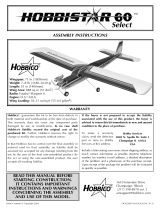
Wingspan: 71" [1,803mm]
Wing area: 887.5" [57.24 sq. dm.]
Weight: 7 lbs [3,630g]
Wing loading: 18 oz/sq ft [55 g/sq. cm]
Length: 55" [1,397mm]
Radio: 4-ch (four servos)
Engine: .61 two-stroke, .91 four-stroke
[10cc 2-stroke, 15cc 4-stroke]

2
You’re about to build in just hours what took aviation pioneers years–a powered machine that flies.
Specially created for you and other first-time radio control modelers, Hobbico’s Hobbistar .60 MKII offers
nearly all the excitement of piloting a real airplane...and develops skills that will take you anywhere you
want in your hobby.
Kit Contents / Ordering Replacement Parts
Need to purchase replacement parts for your Hobbistar .60 MKII ARF? Please see the chart below
regarding purchase information for parts. Please note that only those items listed are available and
individual pieces within a particular set (such as a single aileron or a firewall) cannot be purchased
separately.
Item
Description How to Purchase
Missing pieces Contact Hobby Services (see warranty front page)
Plans Construction Plans Plans are not available for ARF models
Manual Instructions Contact Hobby Services (see warranty front page)
Hardware Individual hardware items Contact your hobby supplier*
HCAA3107 MKII Fuselage Contact your hobby supplier*
HCAA3106 MKII Landing Gear Contact your hobby supplier*
HCAA3108 MKII Wing Set Contact your hobby supplier*
HCAA3109 MKII Tail Set Contact your hobby supplier*
HCAA3104 MKII Wing Tip Contact your hobby supplier*
*Please visit your favorite hobby shop or contact your favorite mail order / Internet order firm to purchase
these items.As a distributor, we support our retailers by referring all business to them, so our support team
does not normally sell these items. Please feel free to visit www.hobbico.com and click on “Where to
Buy” to assist you in locating a dealer in your area.

3
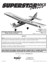
Kit / Airframe Parts & Hardware
Other General Items Required
3
11
11
11
10
16
15
12
5
4
6
8
9
13
2
1
1
7
Hardware
Kit / Airframe Parts
1 Wing with Ailerons
2 Fuselage
3 Stab with Elevators
4 Fin with Rudder
5 Spinner
6 Nose Gear Wire
7 Main Landing Gear Wire (2)
8 Wheels (3)
9 Fuel Tank with Hardware
10 Wing Dowels
11 Wing Joiner
12 Aileron Servo Tray
13 Plywood Servo Tray
14 Engine Mount Straps
15 Aileron Servo Tray Blocks
16 Wing Joining Tape
17 Pushrods and Pushrod Tubes
14
17
Clothespins
Epoxy Brushes (GPMR8062)
Mixing Sticks (GPMR8055)
1/4" Foam Rubber (HCAQ1050)
T-Pins (HCAR5150)
Masking Tape (TOPR8018)
Monofilament String
Felt-Tip Pen
Sanding Block
Adjustable Wrench
Paper Towels
Builders Triangle Set
(HCAR0480)
Plastic Wrap or Wax Paper
Round Toothpicks
Wire Cutter
#64 Rubber Bands
70% Isopropyl Alcohol
Small Hobby Clamps
Razor Saws

4
Other Items You’ll Need:
Glues
Choose 6-minute and 30-minute epoxy, such as Great Planes
®
Pro
™
Epoxy,
which has been formulated especially for R/C model building. Pro Epoxies
offer a strong bond and a variety of curing times suited for every step of
assembly. You’ll also need a thin instant-setting CA (cyanoacrylate),
medium CA+, plus rubbing alcohol for easy epoxy cleanup. Great Planes
Pro Threadlocker is also recommended to secure threaded fasteners.
Model Engine
Power your Hobbistar .60 MKII with a hot
2-stroke such as
an O.S
®
..61 FX.If you prefer a
4-stroke, an O.S. FS-91 is an ideal choice.Your
choice of 2-stroke or 4-stroke will determine the
location of the throttle servo and throttle pushrod
exit on the firewall, so plan ahead.
Radio Equipment
In selecting a radio system for your Hobbistar .60 MKII,
you’ll need at least a 4-channel radio system with four
standard servos. Many of the 4-channel radios offered
include only three servos, so it may be necessary to
purchase an extra servo along with your radio system.
The servos and receiver will be mounted on-board your
model and need to be cushioned from shock and
vibration. One-half inch thick foam rubber sheets
(HCAQ1050) are available from your hobby dealer for this
purpose.
Tools
Tools and accessories required for assembly include a hobby knife; small
and large Phillips screwdrivers; needle nose pliers; electric drill with 1/16"
[1.5mm] and 1/8" [3mm] bits; ruler; 2 feet of medium (3/32") fuel tubing;
and 150 to 200-grit sandpaper.

Your Hobbico Hobbistar .60 MKII is not a toy,
but rather a sophisticated, working model that
functions very much like an actual airplane.
Because of its realistic performance, the
Hobbistar .60 MKII, if not assembled and
operated correctly, could possibly cause injury
to yourself or spectators and damage property.
If this is your first trainer, or if you are
uncomfortable in making the initial flight of
your Hobbistar .60 MKII, it is recommended
that you get help from an experienced,
knowledgeable modeler with your initial
flights.
You may also want to contact the Academy of
Model Aeronautics (AMA), which has more
than 2,500 chartered clubs across the country.
Through the AMA, you should either be able to
locate a modeler nearby that can help, or at
least be able to phone one that can verbally
instruct you for any potential problems that
could occur. Contact the AMA at
the address or
phone number
below:
Academy of Model Aeronautics
5151 East Memorial Drive
Muncie, IN 47302
Office: (765) 287-1256
Toll Free: (800) 435-9262
Fax: (765) 741-0057
Internet:http://www.modelaircraft.org
5
WARNING! This is not a Toy!
Please follow these safety precautions:
Before you fly:
1.Make sure that no other fliers are using your radio
frequency.
2.Your radio transmitter must be the FIRST thing you
turn ON, and the LAST thing you turn OFF.
3.Double check all control surfaces.
4.Make sure that the transmitter & receiver batteries are
fully charged.
Fuel storage and care:
1.Do not smoke near your engine or fuel.
2.Store all engine fuel in a safe, cool, dry place, away
from children and pets. Model fuel will evaporate, so
make sure that you always store it with the
cap secure.
When starting and running your engine:
1.Always wear safety glasses.
2.Make certain that your glow plug clip is securely
attached to the glow plug and cannot pop off, possibly
falling into the spinning propeller.
3.Use a “chicken stick” or electric starter to start the
engine – NOT your fingers.
4.Make sure that the wires from your starter and glow
plug clip cannot become tangled with the spinning
propeller.
5.Do not stand at the side of the propeller when you
start or run the engine. Even at idle speed, the
spinning propeller will be nearly invisible.
6.If any engine adjustments are necessary, approach the
engine only from behind the spinning propeller.
JOIN THE AMA
0" 1" 2" 3" 4" 5"
0 10 20 30 40 50 60 70 80 90 100 110 120 130 140
Inch Scale
Metric Scale
Protect Your Model,Yourself & Others...
Follow This Important Safety Precaution

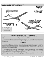
❏ 1. Locate three plywood wing joiners. Using
6-minute epoxy, glue them together to form the
wing joiner.
❏2.After the glue has cured, test fit the joiner into
the wing. Be sure that the upward angle of the
joiner is towards the top of the wing.
❏3. Once you are satisfied with the fit of the wing
joiner, apply a liberal amount of 30-minute epoxy to
the joiner and the wing ribs.Put the wing joiner into
the joiner box in the wing and push the two wing
halves together and allow the glue to cure.
❏4.Use masking tape to hold the two wing halves
together while the epoxy cures. Wipe away any
excess epoxy from the wing surface with Isopropyl
alcohol.
❏5.Locate the plywood aileron servo tray. Place
it in position over the opening in the bottom of the
wing. With a felt-tip pen, mark the position of the
servo tray.
Wing Assembly
6

❏ 6. Use a hobby knife to cut away the material
that you have just marked with the felt-tip pen. Cut
lightly, being sure that you do not cut into the
surface of the wood.
❏7.Use 6-minute epoxy to glue the servo tray to
the
opening in the bottom of the wing. Important
Note:
Before gluing the tray in place, test fit your servo
into the wing. The opening is deep enough to
accommodate most servos.If it is not deep enough
for your particular brand of servos, glue the servo
tray to the two 1/4" [6mm] balsa blocks included in
the kit and then, glue the blocks to the wing
with epoxy.
❏ 8. Locate the blue wing joining material. Peel
off the backing and carefully place it over the seam
on the top and bottom of the wing.
❏1.Cut away the covering at the rear of the
fuselage
for the horizontal stab, fin and pushrod openings.
Cut away the remainder of the stab opening at the
rear of the fuselage with your hobby knife.
Prepare the Fuselage
7

❏ 2. Turn the fuselage over and cut away the
covering on the bottom of the fuselage for the
landing gear.
❏ 3. Cut away the covering at the wing saddle for
the wing hold down dowel holes.
❏ 4. Using 6-minute epoxy, glue the two wooden
dowels in place at the wing saddle.
❏ 5. Fit the horizontal stabilizer in place at the
rear of the fuselage. Do not glue it in place!
❏6. Apply a piece of masking tape across the top
of the fuselage at the back of the wing saddle.
Mark the center of the fuselage on the tape. Insert
a T-pin on the center mark.
❏ 7. Attach one end of monofilament string or a
small tape measure to the T-pin. Measure back to
the end of the stabilizer on the left side of the
fuselage. Do the same for the right side of the
fuselage.When the distance from the T-pin to each
side of the stabilizer is equal, the stab is properly
positioned.
8

❏ 8. Once the stab has been properly positioned,
use a felt-tip marker and trace the outline of the
fuse onto the stabilizer. Do this on both the top and
bottom of the stabilizer.
❏ 9. Cut away the covering inside of the lines you
made on the stab. Do this on both the top and the
bottom of the stabilizer, being careful not to cut into
the wood sheeting.
❏10.Use a few rubber bands and mount the wing
in place on the wing saddle.
❏ 11. With the stabilizer in place in the rear of the
fuselage, step back a few feet and look at the
stabilizer in relation to the wing.The distance from
the top of the stab to the bottom of the wing should
be the same. If each end of the stabilizer is not
equal in distance from the wing, lightly sand one
side of the opening until both ends of the stabilizer
measure the same distance from the wing.
❏ 12. Once you have the stabilizer properly fit to
the fuselage, remove it and apply 6-minute epoxy
to the stabilizer where you cut the material away
and to the wing saddle. Slide the stabilizer into the
fuselage. Re-check to be sure the stabilizer is
positioned properly and that it is in the correct
position in relation to the wing.
❏ 13. After the epoxy has cured on the stabilizer,
test fit the fin into the slot in the top of the fuselage.
9

Use a triangle to make sure that the fin is
perpendicular to the stab. Once you are satisfied
with the fit, glue the fin to the fuselage with
6-minute epoxy.
❏1. Insert the landing gear struts into the holes
in
the bottom of the fuselage.Secure the landing gear
with the two metal straps. Mount them in place with
3mm x 10mm self-tapping screws.
❏2.Draw two lines at the front of the fuselage
with
a felt-tip pen. Draw the lines using the
dimensions
shown in the above photograph.
❏ 3. At the intersection of the two lines drill a 1/8"
[3mm] hole in the fuselage bottom.The hole needs
to be drilled at a 30° angle. Cut one of the white
tubes to 11" and rough it up with 240-grit
sandpaper.
Insert the tube into the fuselage so that the end of
the tube is even with the bottom of the fuselage.
Epoxy the tube to the fuselage.
❏4. Install the nose gear control horn parallel to
the nose gear axle and tighten the mounting screw
against the flat side of the wire.Next install a 4mm
x 10mm collar on top of the control horn and
secure with a 3mm x 4mm screw. Slide the nose
gear shaft through the nose gear mount. Secure
the gear in place with another 4mm x 10mm collar
and a 3mm x 4mm screw.
❏ 5. Locate one of the 18" wire control rods.
Make a 90° bend 5/16" [8mm] from the end of
the wire.
Landing Gear Installation
10

❏ 6. Slide the 18" wire control rod into the white
nylon tube. Install the wire onto the control horn
and retain it in place with the 1/16" wheel collar
and 4-40 set screw.
❏ 7. Install the wheel on the nose gear. The nose
wheel has a slightly smaller axle hole than the
remaining two wheels. Install a 4mm x 10mm
wheel collar and secure it with a 3mm x 4mm
screw. Install a 5mm x 10mm wheel collar on
each side of the main landing gear.Then install the
wheels and the other 5mm x 10mm wheel collar.
Secure the wheel collars with the 3mm x 4mm
screws. All three wheels should turn freely. If not,
trim the inside of the wheel slightly.
❏ 1. Locate the two metal engine mount straps.
❏ 2. Put your engine onto the engine mount.
Note:
Depending on your engine you may need to
cut away portions of the fuselage sides for
clearance for the muffler or needle valve.
Place the
engine mounting straps over the mounting rails of
the engine. Screw the mounting rails in place with
the 4mm x 15mm screws and 4mm lock
washers.
❏ 3. Remove the fuel tank compartment cover
from the fuselage. Locate the white nylon tube
and cut it to a length of 9".Install it through the pre-
drilled hole in the firewall. Epoxy the tube in place
so that 1" of the tube protrudes through the firewall.
Engine Installation
11

❏ 4. Assemble the fuel tank using the above
sketch and the following instructions. Push the two
aluminum tubes through the rubber stopper until
1/2" [13mm] of the tubes protrudes from the front
of the stopper. Slide the large cap onto the front of
the stopper and the small cap onto the back.
Insert the stopper screw into the center hole in
the front of the cap, then just begin to screw it
through the stopper into the aft of the stopper cap.
❏5.Push one end of the silicone pickup tube all
the way onto the clunk, and the other end all the
way onto one aluminum tube. Bend the other
aluminum tube (vent) upward at about a 45° angle,
being careful not to kink the tube.
❏6.Insert the stopper assembly into the fuel tank
and tighten the stopper screw.
❏7.Install the tank into the fuel tank
compartment.
Apply a bead of silicone sealant around the fuel
tank cap when installing the tank into the fuselage.
Attach silicone fuel line from the tank to the
carburetor and muffler pressure fitting.
❏8.Put masking tape onto the fuel tank
compartment
cover as shown. Mark lines on the tape at the
dimensions shown in the photograph. Drill four
1/16" [1.5mm] holes at the intersection of the lines,
drilling through the cover and the four hardwood
blocks in the fuselage. Secure the hatch to the
fuselage with four 2.6mm x 12mm screws.
❏ 1. Locate one of the wooden pushrods with
wire on each end. Insert the threaded end of the
rudder pushrod into the fuselage, working it around
until the end of the pushrod is extending through
the exit hole on the top of the fuselage.
Pushrod Installation
12

❏ 2. Insert the threaded end of the elevator
pushrod into the fuselage, working it around until
the end of the rod is extending through the exit hole
on the lower left side of the fuselage.
❏3.Install the nylon clevis onto the threaded end
of the pushrod. Turn the clevis onto the rod with
14-turns of the clevis.
❏ 4. Position the rudder control horn on the
rudder. Make a mark with a felt-tip pen where the
holes need to be drilled. Note:
When installing the
control horns, the centerline of the control horn
holes must be the same as the center line of the
hinge joint as shown in the above sketch.
Drill a
1/16" [1.5mm] hole through the marks you just
made.Insert the 2mm x 20mm screws through the
control horn and into the control horn backplate.
❏5.Position the elevator control horn on the
elevator
following the same procedure used for the rudder.
❏ 1. Locate the plywood servo tray. Cut off the
portion of the tray indicated by the dashed line.
Radio Installation
INCORRECTCORRECT
HINGE LINE
13

❏ 2. Using the hardware that comes with your
servos, install the servos as shown. Use a 1/6"
[1.5mm] drill to pre-drill the holes for the servo
mounting screws. If you do not pre-drill the holes
there is a chance that the plywood may split.
❏ 3. Use 6-minute epoxy to glue the tray in place
inside of the fuselage.When properly installed, the
servo tray will rest firmly on the rear former.
❏ 4. On both sides of the fuselage there is a cut
out for your radio switch. Cut away the material on
one side of the fuselage for the switch harness.
Mount the switch to the fuselage following the
instructions included with your radio system.
❏ 5. Plug the switch into the receiver and the
receiver battery. Plug the servos into the receiver
(consult your radio instruction manual for proper
installation if you are unfamiliar with this).Wrap the
receiver and the battery in foam rubber.Use rubber
bands to keep the foam in place.It is important that
the receiver and battery be wrapped in the foam to
protect them from engine vibration. Place the
receiver and battery in place as shown. We
recommend that you glue scrap balsa stick to the
fuselage to keep them in place.
❏ 6. Center the trims on the transmitter, turn on
the transmitter and receiver and allow the servos to
center themselves. Once they are centered, install
the servo arms onto the servos, positioning the
arms as shown in the photograph.
14

❏7. Set the rudder and elevator so they are in the
neutral position as shown.
❏ 8. With the elevator servo and the elevator both
in the neutral position, make a mark on the elevator
pushrod where the hole in the servo arm is. Make
a 90° bend at the mark on the pushrod. Insert the
pushrod into the hole in the servo arm and attach
a Great Planes FasLink
™
(GPMQ3820) to the
pushrod. Repeat this step for the rudder pushrod.
Should you decide to use some other installation
method, follow the manufacturer’s instructions.
❏ 9. Locate a screw-lock pushrod connector, a
4-40 set screw and the nylon retainer. Install it on
the remaining arm on the rudder servo by first
sliding the nose gear steering pushrod through the
hole in the fitting and then assembling the screw-
lock pushrod connector as shown in the above
sketch. Set the nose wheel to be straight and then
tighten the 4-40 set screw onto the pushrod wire.
❏10.Turn on the transmitter and receiver. Set the
throttle to full open. Install the pushrod into the
other screw-lock pushrod connector, then open the
carburetor on your engine to full open. Connect the
throttle linkage following the same steps as used
for the nose gear steering.
❏ 11. Install the servo into the plywood servo tray
in the center of the wing.Use a 1/6" [1.5mm] drill to
pre-drill the holes for the servo mounting screws.
❏ 12. Install the clevises on the threaded ends of
the pushrods by turning the clevis 14 times.Thread
the nylon torque rod horn onto the aileron torque
rod and then attach the clevis to the horn.
❏ 13. Connect the aileron servo to the receiver
and center the aileron servo. Center the right
aileron, then align the pushrod to the servo arm.
Make a mark on the pushrod when it is in line with
the hole in the servo horn. Bend the wire 90
degrees on the mark you just made. After making
the bend in the pushrod, install it through the hole
in the servo horn and attach it with a Faslink.
❏14. Follow the same procedure for the left
aileron.
RETAINER
2-56 (.074")
Pushrod Wire
Servo Horn
FasLink
1/16"
15

❏ 15. Cut off two leftover servo arms as shown in
the above diagram. These will be used to make a
simple strain relief for your receiver antenna.
❏ 16. Drill a 1/16" [1.5mm] hole in the fuselage.
❏ 17. After cutting the servo arms, thread the
antenna through the hole you drilled in the
fuselage and attach the antenna to the vertical fin
with a rubber band and T-pin as shown above.
❏ 18. Install the propeller recommended by the
engine manufacturer along with the spinner.
By moving the position of the clevis at the control
horn toward the outermost hole, you will decrease
the amount of throw of the control surface. Moving
it toward the control surface will increase the
amount of throw. If these adjustments don’t
accomplish the job, you may need to work with a
combination of adjustments by also repositioning
the pushrod at the servo end. Moving the pushrod
towards the center of the servo horn will decrease
the control surface throw – outward will increase it.
Control Throw Adjustment
Final Assembly
16

Note: Throws are measured at the widest part of
the elevators, rudder and ailerons.We recommend
the following control surface throws as a starting
point:
One leading cause of crashes is flying an airplane
with its control throws set differently from those
recommended in the instructions. The Great
Planes AccuThrow
™
lets you quickly and easily
measure actual throws first, so you can make
necessary corrections before you fly. Large, no-slip
rubber feet provide a firm grip on covered surfaces
without denting or marring the finish. Spring
tension holds AccuThrow’s plastic ruler steady by
each control surface. Curved to match control
motions, the ruler provides exact readings in both
standard or metric measurements. GPMR2405.
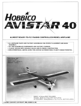
Make sure the control surfaces move in the proper
direction as illustrated in the following sketch:
Note: This section is VERY important and must
NOT be omitted! A model that is not properly
balanced will be unstable and possibly unflyable.
❏1.The balance point (C.G.) is located 3-1/2
[89mm]
back from the leading edge of the wing. Balance
your Hobbistar 60 using a Great Planes C.G.
Machine
™
Airplane Balancer (GPMR2400) for the
most accurate results.This is the balance point at
which your model should balance for your first
flights. Do not at any time balance your model
outside the recommended range.
❏ 2. With the wing attached to the fuselage, all
parts of the model installed (ready to fly), and an
empty fuel tank, block up the tail as necessary to
level the stab. Lift the model at the desired balance
point, and observe the tail of the aircraft. If the tail
drops, the model is “tail heavy” and you must add
weight* to the nose to balance the model. If the
Balance Your Model
CARBURETOR WIDE OPEN
RUDDER MOVES RIGHT
LEFT AILERON MOVES DOWN
RIGHT AILERON MOVES UP
ELEVATOR MOVES UP
4-CHANNEL
TRANSMITTER
(STANDARD MODE 2)
4-CHANNEL RADIO SETUP
TRANSMITTER
4-CHANNEL
TRANSMITTER
4-CHANNEL
TRANSMITTER
4-CHANNEL
Elevator: 1/2" [13mm] Up and Down
Rudder: 1" [26mm] Right and Left
Ailerons: 1/2" [13mm] Up and Down
Control Surface Throws
17

nose drops, it is “nose heavy” and you must add
weight* to the tail to balance the model.
Note: Nose weight may be easily installed by using
a “spinner weight.” Tail weight may be added by
using Great Planes (GPMQ4485) “stick-on” lead
weights.
*If possible, first attempt to balance the model by
changing the position of the receiver battery. If you
are unable to obtain good balance by doing so,
then it will be necessary to add weight to the nose
or tail to achieve the proper balance point.
Remember to secure the receiver and battery after
your model has been balanced.
IMPORTANT: Do not confuse this procedure with
“checking the C.G.” or “balancing the airplane fore
and aft.”
Now that you have the basic airplane nearly
completed, this is a good time to balance the
airplane laterally (side-to-side). Here is how to do
it:
❏ 1. Assemble the model as in preparation for
flight. (No fuel is required for this procedure.)
❏ 2. With the wing level, lift the model by the
engine propeller shaft and the fin post (this may
require two people). Do this several times.
❏ 3. If one wing always drops when you lift the
model, it means that side is heavy. Balance the
airplane by adding weight to the opposite, lighter
wing tip.
Note: An airplane that has been laterally balanced
will track better in loops and other maneuvers.
At this time check all connections including servo
horn screws, clevises, servo cords and extensions.
Follow the battery charging procedures in your
radio instruction manual.You should always charge
your transmitter and receiver batteries the night
before you go flying and at other times as
recommended by the radio manufacturer.
Carefully balance your propellers before flying. An
unbalanced prop is the single most significant
cause of vibration. Not only may engine mounting
screws vibrate out, possibly with disastrous effect,
but vibration may also damage your radio receiver
and battery.Vibration may cause your fuel to foam,
which will, in turn, cause your engine to run lean
or quit.
We use a Top Flite Precision Magnetic Prop
Balancer
™
(TOPQ5700) in the workshop and keep
a Great Planes Fingertip Balancer (GPMQ5000) in
our flight box.
We strongly suggest that the best place to fly is an
AMA chartered club field. Ask the AMA or your
local hobby shop dealer if there is a club in your
area and join. Club fields are set up for R/C flying
and that makes your outing safer and more
enjoyable. The AMA address and telephone
number are in the front of this manual.If a club and
flying site are not available, find a large, grassy
area at least 6 miles away from houses, buildings
and streets and any other R/C radio operation like
R/C boats and R/C cars. A schoolyard may look
inviting but is too close to people, power lines and
possible radio interference.
Find a Safe Place to Fly
Balance the Propeller
Charge the Batteries
Preflight
Balance Your Model Laterally
18

Inspect your radio installation and confirm that all
the control surfaces respond correctly to the
transmitter inputs.The engine operation must also
be checked by confirming that the engine idles
reliably, transitions smoothly and rapidly to full
power and maintains full power, indefinitely. The
engine must be “broken-in”on the ground by
running
it for at least two tanks of fuel. Follow the
engine
manufacturer’s recommendations for
break-in.
Make sure that all screws remain tight, that the
hinges are secure and that the prop is on tight.
Whenever you go to the flying field, check the
operational range of the radio before the first flight
of the day. First, make sure no one else is on your
frequency (channel). With your transmitter on, you
should be able to walk at least 100 feet away from
the model and still have control.While you work the
controls, have a helper stand by your model and
tell you what the control surfaces are doing.
Repeat this test with the engine running at various
speeds with a helper holding the model. If the
control surfaces are not always responding
correctly, do not fly! Find and correct the problem
first.Look for loose servo connections or corrosion,
loose bolts that may cause vibration, a defective
on/off switch, low battery voltage or a defective
receiver battery, a damaged receiver antenna, or a
receiver crystal that may have been damaged from
a previous crash.
Note: Failure to follow these safety precautions
may result in severe injury to yourself and others.
Keep all engine fuel in a safe place, away from high
heat, sparks or flames, as fuel is very flammable.
Do not smoke near the engine or fuel; and
remember that the engine exhaust gives off a great
deal of deadly carbon monoxide. Do not run the
engine in a closed room or garage.
Get help from an experienced pilot when learning
to operate engines.
Use safety glasses when starting or running
engines. Do not run the engine in an area of loose
gravel or sand; the propeller may throw such
material in your face or eyes.
Keep your face and body as well as all spectators
away from the plane of rotation of the propeller as
you start and run the engine.
Keep these items away from the prop: loose
clothing, shirt sleeves, ties, scarfs, long hair or
loose objects such as pencils or screwdrivers that
may fall out of shirt or jacket pockets into the prop.
Use a “chicken stick” or electric starter to start the
engine.Do not use your fingers to flip the propeller.
Make certain the glow plug clip or connector is
secure so that it will not pop off or otherwise get
into the running propeller.
Make all engine adjustments from behind the
rotating propeller.
The engine gets hot! Do not touch it during or right
after operation. Make sure fuel lines are in good
condition so fuel will not leak onto a hot engine,
causing a fire.
To stop a glow engine, cut off the fuel supply by closing
off the fuel line or following the engine manufacturer’s
recommendations. Do not use hands, fingers or any
other body part to try to stop the engine.Do not throw
anything into the propeller of a running engine.
Read and abide by the following Academy of
Model Aeronautics Official Safety Code:
General
1. I will not fly my model aircraft in sanctioned
events, air shows, or model flying demonstrations
until it has been proven to be airworthy by having
been previously successfully flight tested.
2. I will not fly my model aircraft higher than
approximately 400 feet within 3 miles of an airport
without notifying the airport operator. I will give
right of way to and avoid flying in the proximity of
full-scale aircraft. Where necessary an observer
AMA Safety Code (excerpt)
Engine Safety Precautions
Range Check Your Radio
Ground Check the Model
19

shall be used to supervise flying to avoid having
models fly in the proximity of full-scale aircraft.
3. Where established, I will abide by the safety
rules for the flying site I use and I will not willfully
and deliberately fly my models in a careless,
reckless and/or dangerous manner.
7. I will not fly my model unless it is identified with
my name and address or AMA number, on or in
the model.
9. I will not operate models with pyrotechnics (any
device that explodes, burns, or propels a projectile
or any kind).
Radio Control
1. I will have completed a successful radio
equipment ground check before the first flight of a
new or repaired model airplane.
2. I will not fly my model aircraft in the presence of
spectators until I become a qualified flier, unless
assisted by an experienced helper.
3. I will perform my initial turn after takeoff away
from the pit or spectator areas and I will not
thereafter fly over pit or spectator areas, unless
beyond my control.
4. I will operate my model using only radio control
frequencies currently allowed by the Federal
Communications Commission.
You will find the Hobbistar 60 MKII a predictable,
easy flying airplane. The plane is very good for
learning how to fly and will allow you to proceed
into some advanced flying maneuvers once you
have learned the basics.
Before the first flight it is a good idea to taxi the
plane on the ground to get a feel for the ground
handling characteristics of the plane.Once you feel
comfortable with the way it taxis, it is time to line it
up on the end of the runway. Slowly advance the
throttle and use the rudder / nose wheel steering to
maintain a straight run down the runway.When the
airplane begins to pick up significant speed, slowly
pull back on the elevator stick on your radio.
Maintain a gentle climbing attitude until the plane is
approximately 75 feet high, then begin a turn away
from the pit area.
Once airborne, you will find that the plane is a very
predictable and docile flyer. Until you are very
comfortable with the plane, it is recommended that
you practice gentle turns, both to the left and the
right. Once you are comfortable with making both
right and left hand turns you may want to
experiment with rolls and loops. The plane is
capable of most all of the flying maneuvers a
newcomer will ever want to learn.
When it is time to land the plane, set up straight in line
with the end of the runway at approximately 75 feet.
Gradually begin to decrease the power and the plane
will begin to descend. Maintain the wings in a level
Landing
CAUTION (THIS APPLIES TO ALL R/C
AIRPLANES): If, while flying, you notice any
unusual sounds, such as a low-pitched “buzz,” this
may be an indication of control surface “flutter.”
Because flutter can quickly destroy components of
your airplane, any time you detect flutter you must
immediately cut the throttle and land the airplane!
Check all servo grommets for deterioration (this will
indicate which surface fluttered), and make sure all
pushrod linkages are slop-free.If it fluttered once, it
will probably flutter again under similar
circumstances
unless you can eliminate the slop or flexing in the
linkages. Here are some things which can result in
flutter: Excessive hinge gap; Not mounting control
horns solidly; Sloppy fit of clevis pin in the control
horn; Elasticity present in flexible plastic pushrods;
Side-play of pushrod in guide tube caused by tight
bends; Sloppy fit of Z-bend in servo arm;
Insufficient glue used when gluing in the elevator
joiner wire or aileron torque rod; Excessive flexing
of aileron, caused by using too soft balsa aileron;
Excessive “play” or “backlash” in servo gears; and
Insecure servo mounting.
Flying
Takeoff
Flying
20
/