Page is loading ...

WARRANTY
Hobbico guarantees this kit to be free from defects in both material and workmanship at the date of purchase. This warranty does not cover any
component parts damaged by use or modification. In no case shall Hobbico's liability exceed the original cost of the purchased kit. Further, Great
Planes reserves the right to change or modify this warranty without notice.
In that Hobbico has no control over the final assembly or material used for final assembly, no liability shall be assumed nor accepted for any damage
resulting from the use by the user of the final user-assembled product. By the act of using the user-assembled product, the user accepts all resulting liability.
If the buyer is not prepared to accept the liability associated with the use of this product, the buyer is advised to return this kit immediately in new
and unused condition to the place of purchase.
ASSEMBLY INSTRUCTIONS
TM
© Copyright 2003 HCAZ3064 for HCAA2125 V1.1
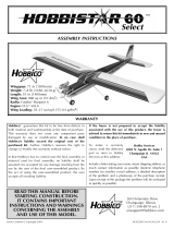
Specifications:
Wingspan: 71 in [1805mm]
Wing Area: 888 sq in [57 dm
2
]
Weight: 7 - 8 lb [3180 - 3630g]
Wing Loading: 18 - 21 oz/sq ft [55 - 64 g/dm
2
]
Length: 55 in [1400mm]
Radio: 4-channel with 4 servos
Engine: .60 to .65 cu in [10.0 – 10.6cc] two-stroke
READ THROUGH THIS MANUAL BEFORE
STARTING CONSTRUCTION. IT CONTAINS
IMPORTANT INSTRUCTIONS AND WARNINGS
CONCERNING THE ASSEMBLY AND USE OF
THIS MODEL.
1610 Interstate Drive
Champaign, IL 61822
(217) 398-8970, Ext. 2
See more of our products at www.hobbico.com

2
INTRODUCTION.................................................2
SAFETY PRECAUTIONS........................................3
ADDITIONAL ITEMS REQUIRED.........................3
Radio system ........................................................3
Engine ..................................................................3
Tools, Building Supplies, Accessories....................4
Optional Supplies and Tools .................................4
Field Equipment....................................................4
KIT INSPECTION .................................................5
ORDERING REPLACEMENT PARTS......................6
TIGHTEN THE COVERING...................................7
PREPARATIONS ...................................................7
ASSEMBLE THE WING .........................................8
Join the ailerons....................................................8
Join the wing ........................................................9
ASSEMBLE THE FUSELAGE.................................10
Mount the stabilizer and fin................................10
Mount the landing gear .....................................13
Mount the engine ...............................................14
Install the fuel tank .............................................15
Mount the aileron servo......................................15
Hook up the controls..........................................16
Mount the muffler, prop and spinner ..................19
PREPARE THE MODEL FOR FLYING ..................20
Balance the model (C.G.) ...................................20
Center the servos ................................................21
Check the control directions...............................22
Center the control surfaces .................................22
Adjust the throttle ...............................................23
Set the control throws.........................................23
Identify your model ............................................24
Balance Propellers ..............................................24
Checklist.............................................................25
Charge the batteries............................................25
Gather your tools................................................25
FLIGHT PREPARATION......................................25
Check the controls..............................................25
Range check .......................................................26
Ground check.....................................................26
ENGINE SAFETY PRECAUTIONS .......................26
AMA SAFETY CODE...........................................27
FLYING...............................................................27
Taxiing ..................................................Back Cover
Takeoff ..................................................Back Cover
Flight.....................................................Back Cover
Landing.................................................Back Cover
MAINTENANCE TIPS............................Back Cover
Congratulations and thank you for purchasing the
Hobbico Hobbistar .60 MKIII. You've made the right
decision by purchasing a “real” model airplane that
uses a .60-size engine and a 4-channel radio. Once
assembled and set up, there will be no fiddling with a
temperamental engine or constant troubleshooting to
figure out how to get the model to fly. Under the
guidance of a flight instructor, all you'll have to do is
concentrate on learning to fly. And after you've
mastered the Hobbistar, the engine and radio may be
installed in your next model!
IMPORTANT:
The best thing you can do to insure success is to
find a flight instructor who will inspect your
model for airworthiness and provide flying
lessons. It cannot be stated strongly enough that,
if you do not already know how to fly an R/C
airplane, you will probably not be able to fly this
model by yourself. It may appear to be easy, but
over-controlling and disorientation quickly
overcome inexperienced fliers swiftly ending their
first flight. If you haven't yet done so, contact the
local hobby shop and ask them to introduce you
to an instructor or an R/C club representative. If
there is no club or experienced R/C pilot nearby,
it would be worth even a long drive to find one-if
only for just a few flight lessons (then you'll have
an idea of what to expect).
If there is no hobby shop in your area, contact the
AMA (Academy of Model Aeronautics), the
governing body of model aeronautics. The AMA
can direct you to the closest R/C club whose
membership should have qualified flight
instructors. With the added benefit of insurance
coverage provided by the AMA, most clubs
require AMA membership to fly at their field.
Academy of Model Aeronautics
5151 East Memorial Drive
Muncie, IN 47302-9252
Tele. (800) 435-9262
Fax (765) 741-0057
Or via the Internet at: http://www.modelaircraft.org
IntroductionTable of Contents

3
1. Your Hobbistar .60 MKIII should not be
considered a toy, but rather a sophisticated, working
model that functions very much like a full-size
airplane. Because of its performance capabilities,
the Hobbistar .60 MKIII, if not assembled and
operated correctly, could possibly cause injury to
yourself or spectators and damage to property.
2. You must assemble the model according to the
instructions. Do not alter or modify the model, as
doing so may result in an unsafe or unflyable model.
In a few cases the instructions may differ slightly
from the photos. In those instances the written
instructions should be considered as correct.
3. You must take time to build straight, true and strong.
4. You must use an R/C radio system that is in first-
class condition, and a correctly sized engine and
components (fuel tank, wheels, etc.) throughout the
building process.
5. You must correctly install all R/C and other
components so that the model operates correctly on
the ground and in the air.
6. You must check the operation of the model before
every flight to insure that all equipment is operating
and that the model has remained structurally sound. Be
sure to check clevises or other connectors often and
replace them if they show any signs of wear or fatigue.
7. If you are not already an experienced R/C pilot,
you should fly the model only with the help of a
competent, experienced R/C pilot.
These are the items not supplied with the Hobbistar .60
MKIII that must be purchased separately. Where
appropriate, order numbers are provided in parentheses.
RADIO SYSTEM
A 4-channel radio control system with four servos is
required to fly the Hobbistar .60 MKIII. 4 “channels”
means that the radio is capable of operating four
controls. On a trainer model such as the Hobbistar
the controls are the ailerons, elevator, throttle and
rudder. Some 4-channel radio control systems
include only three servos, so a fourth servo may
have to be purchased separately.
ENGINE
A .60 to .65 cu in two-stroke model airplane engine
is required to fly the Hobbistar .60 MKIII. Basically,
there are two types of two-stroke engines; “ball
bearing” and “non ball bearing” engines. In addition
to having a crankshaft supported by two ball
bearings, most ball bearing engines have other
performance features that boost power and RPM
(and price). For the Hobbistar .60 MKIII, an
economical, non ball bearing engine is more than
suitable. Should you decide to go “all-out” and
Items Required
We, as the kit manufacturer, provide you with a
top quality kit and instructions, but ultimately the
quality and flyability of your finished model
depends on how you build it; therefore, we
cannot in any way guarantee the performance of
your completed model, and no representations
are expressed or implied as to the performance or
safety of your completed model.
Protect Your Model, Yourself & Others
Follow these Important
Safety Precautions

purchase a more powerful ball bearing engine
anyway, you’ll have to remember to throttle back to
slow the model while learning to fly. A suitable
propeller and spare propellers will also be required
(most two-stroke .60 engines run well with a 12 x 6
or 11 x 7 propeller, but refer to the recommendations
in the instructions that came with the engine).
TOOLS, BUILDING SUPPLIES AND ACCESSORIES
These are the rest of the items required to assemble
the Hobbistar .60 MKIII.
❏6" [150mm] servo extension (HCAM2701 for Futaba
®
)
❏ R/C foam rubber (1/4" [6mm] - HCAQ1000, or
1/2" [13mm] - HCAQ1050)
❏ Medium silicone fuel tubing (GPMQ4131)
❏ #64 rubber bands (1/4 lb [113g] box, HCAQ2020)
❏ Stick-on segmented lead weights (GPMQ4485)
❏Threadlocker thread locking cement (GPMR6060)
❏ 1/2 oz. [15g] Thin Pro
™
CA Glue (GPMR6001)
❏ 1/2 oz. [15g] Medium Pro CA+ Glue (GPMR6007)
❏ Pro 30-minute epoxy (GPMR6047)
❏ Denatured alcohol (for epoxy clean up)
❏ #1 Hobby knife (HCAR0105)
❏ #11 blades (5-pack, HCAR0211)
❏ #1 Phillips screwdriver (HCAR1022)
❏ #2 Phillips screwdriver (HCAR1024)
❏ Pliers
❏ Small metal file
❏ Masking tape
❏ 12mm (or appropriate size) prop wrench or
crescent wrench
❏ Drill and drill bits: 1/16" [1.6mm], 5/64" [2mm],
3/32" [2.4mm], #19 (or 11/64") [4.4mm]
OPTIONAL SUPPLIES AND TOOLS
These items are not absolutely required, but are
mentioned in the instructions and will help you
assemble the Hobbistar .60 MKIII
❏ Top Flite
®
MonoKote
®
sealing iron (TOPR2100)
❏ Top Flite Hot Sock iron cover (TOPR2175)
❏ 4 oz. [113g] aerosol CA activator (GPMR634)
❏ CA applicator tips (HCAR3780)
❏ CA debonder (GPMR6039)
❏ Epoxy brushes (6, GPMR8060)
❏ Mixing sticks (50, GPMR8055)
❏ Mixing cups (GPMR8056)
❏ Builder's Triangle Set (HCAR0480)
❏ Pliers with wire cutter (HCAR0630)
❏ Masking tape (TOPR8018)
❏ K & S #801 Kevlar thread (for stab alignment,
K+SR4575)
❏ Panel Line Pen (TOPQ2510)
❏ CG Machine
™
(GPMR2400)
❏ Precision Magnetic Prop Balancer™ (TOPQ5700)
❏ Prop Reamer (GPMQ5005)
FIELD EQUIPMENT
When ready to fly, you'll need the equipment to fuel
the plane and start the engine. Perhaps you've already
made arrangements with the R/C club or your flight
instructor to borrow theirs, but eventually you'll want
to get your own. Refer to your hobby dealer for
specific recommendations on what to purchase.
Following is a list of the most important items…
❏ Model engine glow fuel (5%, 10% or 15%
nitromethane content is suitable)
❏ Hand-crank or electric fuel pump system with
fuel lines and fittings for transferring fuel from the
container into the fuel tank in the model.
❏ Glow plug igniter for starting the engine
❏ Battery for glow plug igniter (if not already
attached to igniter)
❏ Electric starter and 12v battery
❏ Field box for carrying starting equipment and tools
4

5
1
2
2
6
5
10
9
7
15
14
8
11
12
13
3
4
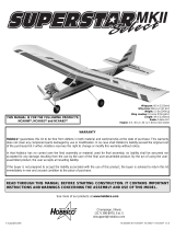
Kit Inspection
1. Fuselage
2. R&L wing halves w/ailerons
3. Stab w/elevator
4. Fin w/rudder
5. Main landing gear wires (2)
6. Nose gear wire
7. Fuel tank w/hardware
8. 1/4" x 1/2" x 10" [6 x 12 x 255mm]
balsa stick (fuel tank, receiver,
battery mounting) (2)
9. Cast aluminum engine mount
10. 2-3/4" [70mm] foam wheels (3)
11. 2-3/4" [70mm] white plastic
spinner w/4 spinner screws
12. 1/8" [3.2mm] plywood fuselage
servo tray
13. 1/8" [3.2mm] plywood wing
servo tray
14. 1/8" [3.2mm] plywood wing
joiners (3)
15. Hardwood wing dowels (2)
Before starting to build, take an inventory of all the parts to make sure the kit is complete and inspect the
parts to make sure they are of acceptable quality. If any parts are missing or are not of acceptable quality,
or if you need assistance with assembly, contact Product Support. When reporting defective or missing
parts, use the part names exactly as they are written in the Kit Contents list on this page.
Product Support:
Telephone: (217) 398-8970
Fax: (217) 398-7721
E-mail: [email protected]
Parts Photographed
(1) nylon nose steering arm
(1) nylon nose gear mount
(2) 2mm x 9-7/8" [250mm] threaded one-end
wire aileron pushrods
(1) 2mm x 27" [685mm] threaded one-end wire
throttle pushrod
(1) 2mm x 19-3/4" [500mm] wire nose wheel
steering pushrod
(2) nylon aileron torque rod horns
(2) nylon straps (main landing gear)
(5) nylon clevises
(5) nylon pushrod keepers
(2) nylon control horns w/mnt plates
(5) silicone retainers for clevises
(15) precut CA hinges
(4) 4 x 25mm Phillips-head screws (engine
mounting)
(6) 4 x 20mm Phillips-head screws (engine
mount, nose gear bearing)
(10) 4mm lock washer
(10) 4mm flat washer
(4) 4mm nut
(2) 2 x 16mm Phillips-head machine screws
(rudder control horn mnt)
(2) 2 x 20mm Phillips-head machine screws
(elevator control horn mnt)
(4) 3 x 12mm Phillips-head self-tapping screws
(main LG straps)
(4) 5mm wheel collars (main wheels)
(5) 4mm wheel collars (nose wheel)
(10) 3 x 5mm screw (for screw-lock connector,
wheel collars)
(1) 3 x 8mm screw (nose steering collar)
(2) 2mm washer (for pushrod connector)
(2) pushrod connector (screw-lock type)
(2) thumb nuts (for pushrod connectors)
(2) metal engine mount straps
(2) aileron torque rods (factory installed in wing)
(6) 4mm blind nuts (factory installed in firewall)
(1) 13-1/2" [340mm] plastic pushrod tube (throttle)
(1) 11-1/4" [285mm] plastic pushrod tube (for
nose wheel)
(2) 36" [915mm] threaded one-end pushrods
(elevator, rudder)
Parts Not Photographed

0" 1" 2" 3" 4" 5"
0 10 20 30 40 50 60 70 80 90 100 110 120 130
Inch Scale
Metric Scale
6
Ordering Replacement Parts
To order replacement parts for the Hobbico Hobbistar .60 MKIII ARF, use the order numbers in the
Replacement Parts List that follows. Replacement parts are available only as listed. Not all parts are
available separately (an aileron cannot be purchased separately, but is only available with the wing kit).
Replacement parts are not available from Product Support, but can be purchased from hobby shops or mail
order/Internet order firms. Hardware items (screws, nuts, bolts) are also available from these outlets. If you
need assistance locating a dealer to purchase parts, visit www.hobbico.com and click on “Where to Buy.”
If this kit is missing parts, contact Product Support.
Item
Description How to Purchase
Missing pieces Contact Product Support
Instruction manual Contact Product Support
Plans Construction Plans Not available
Hardware Individual hardware items Contact your hobby supplier
Parts listed below Contact your hobby supplier
HCAA3120 Fuselage Set (Fuselage, servo tray,wing dowels(2))
HCAA3121 Wing Set (Right & left wing panels w/ailerons, hinges (8), plywood wing
joiners (3), aileron servo tray)
HCAA3122 Tail Set (Fin & rudder, stab & elevator, hinges (7))
HCAA3123 Landing Gear Set (5mm main gear wires (2), 4mm nose gear wire, 5mm wheel
collars & screws (4), 4mm wheel collars & screws (2))
The Hobbistar .60 MKIII ARF is factory-covered with iron-on heat shrinkable model airplane covering.
Should repairs ever be required, the covering can be patched with Top Flite MonoKote or other similar
model airplane covering that has an iron-on adhesive on the back and shrinks with heat. Most coverings
are packaged in six-foot rolls, but some hobby shops sell covering by the foot. If only a small piece is
needed for a minor patch, perhaps a fellow modeler would give you some.
To convert inches to millimeters, multiply inches by 25.4
1/64" = .4mm
1/32" = .8mm
1/16" = 1.6mm
3/32" = 2.4mm
1/8" = 3.2mm
5/32" = 4mm
3/16" = 4.8mm
1/4" = 6.4mm
3/8" = 9.5mm
1/2" = 12.7mm
5/8" = 15.9mm
3/4" = 19mm
1" = 25.4mm
2" = 50.8mm
3" = 76.2mm
6" = 152.4mm
12" = 304.8mm
15" = 381mm
18" = 457.2mm
21" = 533.4mm
24" = 609.6mm
30" = 762mm
36" = 914.4mm
Metric Conversions

Examine the covering on the model. Occasionally,
the covering requires tightening to remove wrinkles
that develop. If necessary, use a model airplane
covering iron with a covering sock to tighten the
covering and remove wrinkles. Hint: Poke three or
four pin holes in the covering between the “ribs” in
the tail surfaces, allowing air to escape to fully
tighten the covering. Note: If you haven't yet
purchased a covering iron (or borrowed one from a
friend), this step may be done later.
There are a few steps that require 30-minute epoxy
that can be done first to speed assembly.
❏ 1. Use 30-minute epoxy to glue together the three
1/8" [3.2mm] plywood wing joiners. Be certain to
apply epoxy to all mating surfaces. (In other words,
apply epoxy to both sides of the joiner in the middle
and to the inside of both the joiner on the top and the
joiner on the bottom.) Hold the joiners together with
clamps. Wipe away excess epoxy before it hardens.
❏ 2. Round the ends of both 1/4" [6.5mm] wing
dowels. Cut the covering from the holes in the
fuselage for the dowels and glue them into position
with 30-minute epoxy. Lightly coat the dowels with
epoxy. (Only the front dowel is shown in the photo,
but there is a dowel at the aft end of the cutout in the
fuselage for the wing.)
❏ 3. Use a hobby knife to bevel the inside edges of
the holes in the main landing gear rail where
indicated by the arrows to accommodate the bend
in the landing gear wire. Seal the exposed wood in
the landing gear rail with a light coat of epoxy.
Preparations
Tighten the Covering
7

❏ 4. Seal the edges of the covering around the
engine compartment with a thin coat of 30-minute
epoxy. Also use 30-minute epoxy to lightly coat the
inside of the fuselage all the way around the
opening for the wing (as indicated by the shaded
area). This will fuelproof the bare wood in case
engine exhaust residue seeps in.
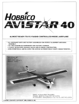
JOIN THE AILERONS
Start with the right wing so yours matches the
photos the first time through.
❏❏1. Use a hobby knife with a #11 blade to neatly
trim the covering from the bottom of the right wing
around the aileron torque rod to allow full, unrestricted
movement of the rod.
❏❏2. Test fit the aileron to the wing with four CA
hinges but do not glue them in yet. If it is difficult to
join the aileron to the wing because the hinge slots
are too tight, remove the hinges. Widen the hinge
slots by inserting a #11 blade and moving it back
and forth a few times.
❏❏3. Remove the aileron from the wing. Drill a
3/32" [2.4mm] hole 1/2" [13mm] deep in the center
of the hinge slots to allow the thin CA used for gluing
in the hinges to fully “wick” all the way in. Cut a small
strip of covering from all the hinge slots in the wing
and aileron. For the best result, use a high-speed tool
such as a Dremel to drill the holes.
AWAY FROM THE SLOT
CUT THE COVERING
DRILL A 3/32" HOLE
1/2" DEEP, IN CENTER
OF HINGE SLOT
Assemble the Wing
8

❏❏4. Tape a small piece of wax paper or a piece of
plastic from a sandwich bag to the wing under the
aileron torque rod. Coat the “arm” portion of the
torque rod and the hole and the slot in the aileron for
the torque rod with 30-minute epoxy. Immediately
proceed to the next step.
❏❏5. Join the aileron to the torque rod and wing
with the hinges. If the hinges don't remain centered,
stick a pin through the hinge to hold it in position.
Be certain there is a small gap between the aileron
and the wing—just enough to slip a piece of paper
through or to see light through. Remove any pins
that were used to center the hinges.
❏❏6. Apply six drops of thin CA to both sides of all
the hinges. Allow a few seconds between drops so
the CA fully soaks into the hinge rather than being
drawn into the hinge gap thus gluing the aileron to
the wing. Note the CA applicator tip (HCAR3780)
on the CA bottle to control and pinpoint the CA that
comes out.
❏❏7. Stack a few paper towels over each other and
cut them into approximately 2" [50mm] squares.
Moisten one of the squares with denatured alcohol
and use it to wipe away excess epoxy that came out
of the aileron.
❏ 8. Return to step 1 and join the left aileron to the
left wing panel the same way.
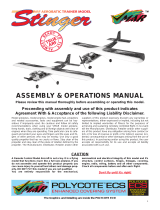
JOIN THE WING
❏ 1. Test fit the aileron servo in both wing halves to
make sure the servo fits. If necessary, enlarge the cut
outs in the wing to accommodate the servo.
❏ 2. Test fit the wing joiner you glued together earlier
into both wing halves, then test fit the wing halves
with the joiner. There should be no gap in the wing.
2-3/8" (± 3/8")
9
T
H
IN
C
A

Make certain the joiner is installed upright (so the
wing tips are higher than the middle of the wing).
Make adjustments where necessary for a good fit
(sanding the top and bottom of the joiner to even the
edges or remove excess epoxy may be required).
Note: The wing dihedral (or upward angle between
the joining wing halves) is factory set and is
determined by the shape of the wing joiners.
However, some modelers prefer to check the wing
dihedral anyway. To do so, lay one wing half on a flat
surface. As shown in the sketch, the end of the other
wing (not including the wing tip) should be 2-3/8"
above the surface. A variance of approximately 3/8"
is acceptable.
❏ 3. Separate the wing halves and remove the
joiner. Thoroughly coat the end of one wing half and
the inside of the wing where the joiner fits with 30-
minute epoxy. Also coat one half of the joiner all the
way around. Install the coated end of the joiner into
the wing half. Proceed immediately to the next step.
❏ 4. Coat the inside and the end of the other wing
with 30-minute epoxy. Also coat the end of the
joiner that is sticking out of the other wing half. Fit
the wings together.
❏ 5. Tightly hold both wing halves together with
several strips of masking tape on both the top and
bottom of the wing. Be certain the leading and
trailing edges of the wing align. As you apply the tape,
wipe away excess epoxy that comes out. Do not
disturb the wing until the epoxy has fully hardened.
MOUNT THE STABILIZER AND FIN
❏ 1. The same as was done for the wing and ailerons,
prepare the stabilizer and elevator and fin and rudder
for hinging (by test fitting the hinges, cutting a strip of
covering from the slots and drilling the holes). Do not
glue in the hinges until instructed to do so.
❏ 2. Cut the covering from the slots in the fuselage
for the stabilizer and fin. Also cut the covering from
the pushrod tubes on the top and left side of the fuse
(where indicated by the arrows in the photo).
❏ 3. Taking accurate measurements, mark the center
of the stab on the trailing edge. Position the stab in
the fuselage. Center the mark on the trailing edge
with the end of the fuse.
Assemble the Fuselage
10

❏ 4. Turn the fuse upside-down. Stick a T-pin
through the bottom of the firewall centered side-to-
side. Tie a small loop in one end of a 50" [1300mm]
piece of non-elastic string such as monofilament or
Kevlar line (K+SR4575) and slip it over the T-pin.
❏ 5. Fold a piece of masking tape over the string
near the other end and draw an arrow on it. Slide the
tape along the string and align the arrow with one
end of the stab as shown in the photo. Swing the
string over to the same position on the other end of
the stab. While keeping the stab centered from side-
to-side, adjust the stab and slide the tape along the
string until the arrow aligns with both ends of the
stab and the stab is centered as shown by A=A' in
the sketch. Be certain the centerline on the trailing
edge remains centered in the fuselage.
❏ 6. Use a fine-point felt-tip pen such as a Top Flite
®
Panel Line Pen (TOPQ2510) to mark the outline of
the fuselage on the top and bottom of the stab.
❏ 7. Remove the stab from the fuse. Use a sharp #11
hobby knife or follow the Expert Tip below to cut the
covering from the stab along the lines. Use care to
cut only into the covering and not into the wood.
Cutting into the balsa will weaken the structure.
Expert
Expert
T
T
ip:
ip:
How to cut covering from balsa.
To avoid cutting into the balsa, use a soldering iron
instead of a hobby knife to cut the covering. The tip
of the soldering iron doesn't have to be sharp, but a
fine tip does work best. Allow the iron to heat fully.
Use a straightedge to guide the soldering iron at a
rate that will just melt through the covering and not
burn into the wood. The hotter the soldering iron,
the faster it must travel to melt a fine cut.
A'
A
A = A'
11

❏ 8. Peel the covering from the stab. Remove any
ink left on the stab with one of the small paper towel
squares you cut earlier, moistened with denatured
alcohol. Also remove any ink around the slot for the
stab that may be on the fuselage.
❏ 9. Mount the wing to the fuselage with a couple
of #64 rubber bands. Slide the stab back into the
fuselage. Stand eight to ten feet behind the model
and observe the alignment between the stab and
wing. If the stab does not align with the wing, place
a small weight on the “high side” of the stab to bring
it into alignment. If weight is not enough to tilt the
stab to one side, remove the stab from the fuselage.
Carefully sand the slot in the fuselage as necessary
to get the stab to align with the wing.
❏ 10. Thoroughly coat the slot in the fuselage for the
stab and the stab where it contacts the fuselage with
30-minute epoxy. Working quickly, slide the stab
into position. Wipe off any epoxy deposited on the
stab. Use the pin and string to be certain the stab is
in alignment. Use a small clamp to hold the stab in
position until the epoxy hardens.
❏ 11. The same as was done to the stab, trim the
covering from both sides of the fin where it will be
glued into the fuselage. Also trim the covering from
the top of the fuselage just in front of and behind the
slot in the fuse where the fin will go.
❏ 12. Use 30-minute epoxy to glue the fin to the fuse.
Hold the fin in position with masking tape. Before the
epoxy hardens, use a Hobbico
®
Builder's Triangle
(HCAR0480) to see if the fin is perpendicular to the
stab. If necessary, adjust the tension on the tape to
pull the fin to one side or the other until it is vertical.
❏ 13. Permanently join the elevator to the stab and
the rudder to the fin with the hinges and thin CA.
12

MOUNT THE LANDING GEAR
❏ 1. Mount the main wheels to the main landing
gear wires using a 5mm wheel collar and a 3 x 5mm
Phillips-head screw on both sides of each wheel.
Before mounting the outer wheel collar (that holds
the wheel on), file a flat spot on the wire for the set
screw. This will ensure that the wheel collar remains
secure so the wheels won't fall off! Note: Before
installing the set screws in the wheel collars, add a
small drop of threadlocker to the screw.
❏2. Add a small drop of oil to both sides of the wheels.
❏ 3. Install the main landing gear wires into the
main landing gear rail in the fuselage. Using the
holes in one of the nylon landing gear straps as a
guide, drill 3/32" holes through the landing gear rail
for the mounting screws. Run a 3 x 12mm screw in
and out of each hole a few times, then add a few
drops of thin CA to the holes. Allow the CA to fully
harden, then mount the straps to the fuselage with
four 3 x 12mm screws.
❏ 4. Mount the engine mount to the firewall with
four 4 x 20mm screws and 4mm washers and lock
washers. Be certain to securely tighten the screws
using a #2 Phillips screwdriver.
❏ 5. Mount the nose wheel to the nose gear wire
with a 4mm wheel collar and a 3 x 5mm screw on
both sides of the wheel. The same as the main
wheels, be certain to file a flat spot on the wire for
the outer wheel collar and add a drop of oil to both
sides of the wheel to help it spin freely.
Refer to this photo for the following two steps.
❏ 6. Insert two 4 x 20mm screws and 4mm lock
washers into the holes in the nylon nose gear mount.
Insert two 4mm flat washers onto each screw on the
back of the nose gear mount. Mount the nose gear
mount to the firewall.
❏ 7. Insert the nose gear wire into the nose gear
mount and the bottom hole in the engine mount. If
the nose gear wire will not go in, or if it will not turn
easily once inserted, remove the nose gear wire. Drill-
out the nose gear mount and the bottom hole in the
engine mount with a #19 (or 11/64") [4.4mm] drill.
This will align the holes. Install the nose gear wire.
❏ 8. Enlarge the inner hole in the nylon steering arm
with a 5/64" [2mm] (or 3/32" [2.4mm]) drill and cut
the outer “two holes” off. Insert a 4mm wheel collar
into the steering arm, then screw in a 3 x 8mm
Phillips-head screw. Insert a threaded pushrod
13

connector into the hole, then slip on a washer. Add
a small drop of threadlocker to the threads, then
screw on a thumb nut. Tighten the nut, but not so
much as to stop the connecter from rotating in the
hole. IMPORTANT: As the thumb nut cannot be fully
tightened, threadlocker must be used on the threads
to keep it from coming off.
Refer to this photo for the following three steps.
❏ 9. Temporarily mount the nose gear using the
steering arm and two 4mm wheel collars with 3 x
5mm screws as shown.
❏ 10. Cut the 11-1/4" [285mm] plastic pushrod tube
to a length of 6-1/2" [165mm]. Roughen the outside of
the tube so glue will adhere and insert it through the
hole in the firewall, through the large hole in the
former behind the firewall and through the hole in the
former behind that. Make sure the front of the pushrod
tube is even with the front of the firewall. Glue the
pushrod tube into the firewall and the third former.
❏11. Slide the 2mm x 19-3/4" [500mm] non-threaded
wire pushrod through the connector on the steering
arm and into the pushrod tube in the firewall. If
necessary, bend the front of the pushrod to align with
the connector then cut the pushrod to the correct
length. Temporarily fasten the pushrod to the
connector with a 3 x 5mm screw.
❏ 12. Mount the wing to the fuselage with two #64
rubber bands. Place the model on its landing gear. Set
the engine (or anything heavy enough to hold the front
end down) on the engine mount. View the model from
the side. Raise or lower the nose gear until the model
is level. Using a small drop of thread locking
compound on the screws in the wheel collars, tighten
the screws to securely lock the nose gear into position.
MOUNT THE ENGINE
Refer to this photo to mount the engine.
❏ 1. Place the engine on the engine mount, then
place the metal mounting plates on both sides of the
engine. Install four 4 x 25mm screws with 4mm lock
washers and 4mm flat washers into the holes in the
plate and the engine mount. One at a time, install a
4mm nut into the recesses in the bottom of the
engine mount and thread them onto the screws, but
do not fully tighten the screws.
❏ 2. If necessary, enlarge the hole in the back plate
of the spinner, then place it on the engine.
❏ 3. Center the engine on the mount, then use a #2
Phillips screwdriver to securely tighten the engine
mounting screws.
14

❏ 4. Test fit the muffler to the engine. If necessary,
use a Dremel tool with a drum sander or a hobby
knife to trim the fuselage to accommodate the
muffler. (If using a Dremel, stuff the engine exhaust
and the opening in the carburetor with a piece of a
paper towel to keep dust from entering.) Coat the
exposed wood with epoxy or medium CA.
INSTALL THE FUEL TANK
Refer to the photo and the sketch while
installing the fuel tank.
❏ 1. Pull the stopper out of the fuel tank and shake
out the contents. Note that there are three holes in
the back of the stopper, but two holes in the front.
The fuel system on this model requires only two
lines (a fuel pickup line and the pressure line), so the
third hole in the stopper will not be used.
❏ 2. Insert the long aluminum tube into the metal
front plate and push it through the hole in the right
side of the stopper until approximately 1/2" [13mm]
of the tube protrudes from the front. Insert the short
aluminum tube through the other hole.
❏ 3. Tighten the screw just until the metal back plate
contacts the back of the stopper. Bend the long
aluminum tube upward as shown in the photo so it
will be near the top of the tank when the assembly
is installed in the tank.
❏ 4. Fit the fuel line to the short aluminum tube. Cut
the fuel line to the correct length so that when the
fuel line weight (“clunk”) is installed, it will be near,
but not contacting the back of the tank. Otherwise,
the line may become stuck above the fuel level
discontinuing fuel flow.
❏5. Note that the tube in the right side of the tank is the
pressure line that will be connected to the muffler and
the tube in the left side of the tank is the fuel tube which
will be connected to the carburetor. Install the stopper
and fuel line assembly into the tank. Make certain the
clunk is not contacting the back of the tank, then tighten
the screw to expand the stopper, thus sealing the tank –
approximately five or six full turns should be adequate.
❏ 6. Install the fuel tank into the fuselage with the
neck of the tank through the hole in the firewall. Cut
3-1/8" [80mm] from one of the 1/4" x 1/2" x 10"
[6 x 12 x 255mm] balsa sticks. Trim the 3-1/8"
[80mm] piece as necessary to fit between the back
of the tank and the former to secure the fuel tank.
MOUNT THE AILERON SERVO
❏ 1. Cut a small hole in the bottom of the wing for
the servo wire. Cut the covering from the wing for
the 1/8" [3.2mm] plywood aileron servo tray.
Pressure Line
(to muffler)
Fuel Pickup Line
(to carburetor)
"Clunk"
Silicone
Fuel Line
Firewall
Aluminum
Tubes
15

Refer to this photo while mounting the aileron servo.
❏ 2. Use epoxy to glue the aileron servo tray to
the wing.
❏ 3. Drill 1/16" holes through the servo tray for
mounting the servo. Run the servo screws in and out
of the holes a few times to make some threads in the
wood. Add a few drops of thin CA to the holes and
allow to fully harden. Mount the servo in the wing
using the screws that came with the servo.
❏ 4. Make a two-arm servo arm from a four-arm
servo arm by cutting two of the arms off. Mount the
servo arm to the servo.
❏ 5. Screw a nylon clevis twenty-five full turns onto
a 2mm x 9-7/8" [250mm] pushrod. Make another
pushrod the same way. Screw the nylon torque rod
horns twelve full turns onto the aileron torque rods.
❏ 6. Connect one of the clevises on the pushrod to
one of the torque rod horns. Make a 90-degree bend
in the pushrod so that when connected to the servo
arm, the aileron will be centered. Fit the pushrod in
the second from the outer hole in the servo arm,
then secure it with a nylon pushrod keeper. Cut the
pushrod 1/16" [2mm] from the keeper as shown in
the sketch. Note: It may be necessary to enlarge the
holes in the servo arm to fit the pushrod. If so, use a
hobby knife with a #11 blade to carefully enlarge
the holes from both sides of the arm.
❏ 7. Connect the other pushrod to the servo arm and
the torque rod the same way.
❏ 8. Center the servo arm. Adjust the length of the
pushrods by turning the clevises in or out until both
ailerons are centered.
HOOK UP THE CONTROLS
Refer to this photo for the following three steps.
❏ 1. Make two one-arm servo arms from the arms
that came with the servos. Also make one two-arm
servo arm.
❏ 2. Install the arms on the servos, then test fit the
servos in the 1/8" [3.2mm] plywood fuselage servo
tray as shown. If necessary, enlarge the openings in
the tray to accommodate your servos.
❏ 3. Drill 1/16" holes through the servo tray for
mounting the servos. Run the servo screws in and
out of the holes a few times to make some threads in
the wood. Add a few drops of thin CA to the holes
to harden the threads. After the CA has fully
hardened, mount the servos in the tray.
❏ 4. Refer to the photo at step 6. Use epoxy to
securely glue the servo tray in the fuselage. Cut the
elevator and rudder pushrod tubes so they “end”
approximately 1/8" [3mm] ahead of the former on
the aft end of the servo tray.
Keeper
Pushrod Wir
e
Servo
Arm
Keeper
16

❏ 5. Screw a clevis twenty-five full turns onto a
2-56 x 36" [915mm] pushrod. Connect the clevis to
the second-from-the-outer hole of a control horn.
Make another pushrod assembly the same way.
❏ 6. Slide the pushrods into the pushrod tubes in the
fuselage. Position the control horn on the rudder as
shown in the photo and sketch. Use the control horn
as a guide to drill two 5/64" [2mm] (or 3/32"
[2.4mm]) holes through the rudder for the mounting
screws. Mount the control horn to the rudder with
two 2 x 16mm Phillips-head screws and the plastic
mounting plate.
❏ 7. Mount the elevator control horn to the elevator
with two 2 x 20mm Phillips-head screws.
❏ 8. Carefully enlarge the holes in the elevator and
rudder servo arms with a hobby knife and a #11 blade
or a 5/64" [2mm] drill.
Refer to this photo while connecting the
pushrods to the servos.
❏ 9. Make a 90-degree bend in the elevator pushrod
so the elevator will be centered when the pushrod is
connected to the servo arm. This is most easily done
by disconnecting the pushrod from the elevator,
rotating the pushrod 90-degrees, then making the
bend to the side. The clevis on the back of the
pushrod will now have to be turned 90-degrees the
other way. Take the servo arm off the elevator servos
and fit the pushrod in the third hole out. Install the
pushrod keeper, then cut the wire so 1/16" [2mm]
protrudes. Reinstall the servo arm and clevis.
❏ 10. Connect the rudder and nose wheel pushrod
the same way. A few bends will have to be made in
the nose wheel pushrod to align it with the servo arm.
❏ 11. Use the remaining 13-1/2" [340mm] plastic
pushrod tube and the 2mm x 27" [685mm] threaded
The Holes in the
Control Horn
Align with the
Pivot Point
Control
Horn
Mounting
Plate
Pivot
Point
17

one-end wire pushrod to hook up the throttle. A
nylon clevis is used on the aft end of the pushrod to
connect it to the servo arm and a threaded pushrod
connector is used on the front of the pushrod to
connect it to the carburetor arm. Bend the pushrod
as necessary to align it with the threaded pushrod
connector and be certain to use threadlocker on the
thumb nut. Adjust the pushrod so the carburetor is
half-open when the throttle servo arm is centered.
❏12. Wrap the receiver and battery pack in 1/4" [6mm]
(or 1/2" [13mm]) R/C foam rubber. Hold the foam
rubber in place with tape or rubber bands. Connect a
servo extension cord to the aileron plug in the receiver
(numbered “1” on most receivers) and connect the
on/off switch to the receiver as well. Connect the battery
to the switch.
❏ 13. Connect the throttle, elevator and rudder servos
to the receiver. Place the receiver and battery in the
fuselage, then glue pieces of the 1/4" x 1/2" [6 x 13mm]
balsa stick to the fuselage sides across the receiver and
battery to securely hold them down. Make certain
nothing interferes with the movement of the throttle or
nose wheel steering pushrods. Cut the covering from
the square hole in the left side of the fuselage for the
on/off switch. Drill two 3/32" [2.4mm] holes for the
switch mounting screws and mount the switch.
❏ 14. Glue leftover pieces of pushrod tubing inside
the fuselage to guide the receiver antenna away
from the servos and pushrods. Route the antenna
through the tubes. Make a “strain relief” from a cut
off servo arm and route the antenna through two of
the holes. Drill a 1/16" [1.6mm] hole through the
fuselage side for routing the antenna. Route the
antenna through the hole in the fuselage.
❏ 15. Make a “hook” for the antenna from another
cut off servo arm and connect it to the antenna. Use
needle nose pliers to make a loop on the end of a pin
or a small piece of wire. Stick the wire into the top of
the fin and connect it to a small rubber band which
is, in turn, connected to the hook on the antenna.
18

MOUNT THE MUFFLER, PROP AND FUEL LINES
Refer to this photo while mounting the muffler
and installing the fuel lines.
❏ 1. Mount the muffler to the engine. Note that on
some engines the exhaust outlet may be rotated so
the engine exhaust can be directed away from the
model. Rotate the outlet if necessary.
❏ 2. Using medium silicone fuel tubing, connect the
vent/pressure tube coming from the fuel tank to the
muffler and connect the pickup tube coming from
the fuel tank to the carburetor. If using the O.S.
®
MAX .65 LA or another engine with a remote needle
valve, make the fuel line a little extra long so it will
be easier to handle the line for filling the fuel tank
(as the tank is filled through this line).
❏ 3. Fit the back-plate of the spinner and a suitable
propeller to the engine. If the hole in the back-plate
and prop are too small, use a prop reamer or the
correct-size drill to enlarge the holes (a 5/16" drill is
suitable for engines that have a 5/16"-24 crank shaft
such as the O.S. MAX .65 LA). A prop reamer is best
as it self-centers as it enlarges the hole.
❏ 4. Install the prop washer and prop nut. Tighten
the prop nut “finger-tight,” then use the correct-size
wrench (12mm for most engines) to tighten the prop
nut by turning it 1/2 turn, plus another 1/8 turn. This
should be adequate tightness.
❏ 5. Fit the spinner cone over the propeller onto the
spinner back plate, then secure with the four screws
that came with the spinner.
+ 1/8 Turn
1/2 Turn
19

BALANCE THE MODEL (C.G.)
At this time the model must be in “ready-to-fly”
condition with all components installed including
the complete radio system, landing gear, engine,
prop and spinner. The model is to be balanced with
the fuel tank empty.
❏ 1. If using a Great Planes
®
C.G. Machine
™
to
balance the model, set the rulers to 3" [76mm]. If
you do not have a Great Planes C.G. Machine, use
a felt-tip pen or 1/16" to 1/8" [1.5 to 3mm] tape to
accurately mark the C.G. 3" [76mm] from the
leading edge on the bottom of the wing.
❏ 2. Mount the wing to the fuselage with at least four
#64 rubber bands. If using a C.G. Machine, place the
model on the machine. If not using a C.G. Machine, use
the tip of your middle fingers on both hands to lift the
model by the wing on both sides of the fuselage at the
balance point you marked on the bottom of the wing.
❏ 3. If the fuselage is level when lifting the model the
C.G. is correct. If the nose drops the model is nose-
heavy and will require weight on the tail to balance.
This is where the model should balance for the first
flights. Later, you may wish to experiment by shifting
the C.G. up to 1/2" [13mm] forward or 1/2" [13mm]
back to change the flying characteristics. Moving the
C.G. forward will increase stability, but will decrease
the model's aerobatic capabilities by decreasing
maneuverability. Moving the C.G. aft will have the
opposite effect. In any case, as long as the model is
balanced within the recommended range it will not
display any bad tendencies. Do not at any time
balance the model outside the recommended range.
More than any other factor, the C.G. (center of
gravity, also referred to as the balance point) can
have the greatest effect on how a model flies and
may determine whether or not the first flight will be
successful. If the plane is nose heavy it could be
difficult to takeoff and land and lose some of its self-
recovery capabilities. If the plane is tail heavy the
controls may be too sensitive, making the model
overreact to control inputs. If you value this model
and wish to enjoy it for many flights, DO NOT
OVERLOOK THIS IMPORTANT PROCEDURE. A
model that is not properly balanced will be unstable
and possibly unflyable.
Prepare the Model for Flying
20
/