Page is loading ...

ASSEMBLE ONLY WITH ADULT SUPERVISION
Please read through this instruction booklet to THOROUGHLY familiarize yourself with the assembly and
flight characteristics of this airplane before beginning to assemble the kit.
Please inspect all parts carefully before starting assembly! If any parts are missing, broken or defective, or if
you have any questions about the assembly or flying of this airplane, please call us at (217) 398-8970 and
we'll be glad to help.
WARRANTY
Hobbico, Inc. guarantees this kit to be free from defects in both material and workmanship at the date of
purchase. This warranty does not cover any component parts damaged by use or modification. In no case
shall Hobbico's liability exceed the original cost of the purchased kit. Further, Hobbico reserves the right to
change or modify this warranty without notice.
In that Hobbico has no control over the final assembly, no liability shall be assumed nor accepted for any
damage resulting from the use by the user of the final user-assembled product. By the act of using the user-
assembled product, the user accepts all resulting liability.
If the buyers are not prepared to accept the liability associated with the use of this product, they are
advised to return this kit immediately in new and unused condition to the place of purchase.
C
C
OMPLETE R
OMPLETE R
TF
TF
AIRPLANE
AIRPLANE
8 (AA) Alkaline Batteries
(not included)
Quiet Electric Flight
Radio-Controlled Model
Entire Contents © Copyright 1998
HCAZ
3072 V1.0
™

Your Skyrunner is not a toy, but rather a sophisticated,
working model that functions very much like an actual
airplane. Because of its realistic performance, the
model, if not assembled and operated correctly, could
possibly cause injury to yourself and spectators or
damage property.
We highly recommend that you get experienced,
knowledgeable help with assembly and during your
first flights, to make your R/C modeling experience
totally enjoyable. You'll learn faster and avoid risking
your model before you're truly ready to solo. Your
local hobby shop has information about flying clubs in
your area whose membership includes qualified
instructors.
You can also contact the national Academy of
Model Aeronautics (AMA), which has more than 2,500
chartered clubs across the country. Instructor training
programs and insured newcomer training are available
through any one of these clubs.
Contact the AMA at the address or toll-free phone
number below.
Academy of Model Aeronautics
5151 East Memorial Drive
Muncie, IN 47302
(800) 435-9262
Fax (765) 741-0057
or via the internet at: http://www.modelaircraft.org
1. Assemble the plane according to the instructions.Do
not alter or modify the model. If you make any
modifications, you will void your warranty.
2. Test the operation of the model before each flight
to insure that all equipment is operating properly, and
that the model remains structurally sound.
3. Fly only on calm days (wind speeds less than
7mph) and in large open areas free of trees, people,
buildings or any other obstacles.
Remember: Take your time and follow the
instructions to end up with a well-built model that is
straight, durable and easy to fly.
The R/C model hobby becomes more and more
enjoyable as your experience grows. Your chances for
success and graduation to higher levels are very good
if you take your time and follow the assembly and
flying instructions carefully and completely.
We hope you enjoy flying your Skyrunner.
Carefully unpack the box and lay out the parts. Check
the parts against the list below. If any parts are
damaged or missing, give us a call at: (217)398-8970.
Part# Part name: Qty:
❑ 1. Decals 1
❑ 2. Fuselage 1
❑ 3. Wing 1
❑ 4. Wing Center Brace 1
❑ 5. Aluminum Wing Dowels 2
❑ 6. Rubber Bands 4
❑ 7. NiCd Battery Pack (in fuselage) 1
❑ 8. Battery Charger 1
❑ 9. Horizontal Stabilizer (stab) 1
❑ 10. Vertical Stabilizer (fin) 1
❑ 11. Transmitter 1
❑ 12. Transmitter Antenna 1
❑ 13. Transmitter Flag 1
❑ 14. Servo Accessory pack (not used) 1
❑ 15. Propeller 1
❑ 16. Spinner Insert 1
❑ 17. Spinner Base 1
❑ 18. Spinner Cone (rubber) 1
❑ 19. Prop Nut 1
❑ 20. Landing Gear 1
❑ 21. Glue 1
❑ 22. Sandpaper 1
❑ 23. Reinforcement Tape 1
Very few tools are needed to build the Skyrunner
airplane. Please gather these together before starting to
build.
❑ Pliers
❑ Scissors
2
PRO
PRO
TECT
TECT
Y
Y
OUR MODEL,
OUR MODEL,
Y
Y
OURSELF
OURSELF
AND
AND
O
O
THERS.
THERS.
FOLLO
FOLLO
W
W
THIS IMPOR
THIS IMPOR
T
T
ANT SAFETY
ANT SAFETY
PREC
PREC
A
A
UTION
UTION
PREC
PREC
A
A
UTIONS
UTIONS
UNP
UNP
A
A
CKING
CKING
THE BO
THE BO
X
X
SUPPLIES NEEDED FOR
SUPPLIES NEEDED FOR
ASSEMBL
ASSEMBL
Y
Y

❑ Phillips screwdriver
Charge the battery before assembling the airplane.
You will need to use the battery to set up the radio
system during assembly.
Charging the battery pack is safe and easy when
you follow these instructions. Before charging, make
sure that all wires and connectors are in good shape
and properly insulated.
1. Connect the included battery charger to a 110 volt
A/C wall outlet.
2. Remove the battery pack from the airplane and
make sure it is cool to the touch. Plug the battery into
the charger connector. Be careful; the battery will plug
in only one way.
3. Allow the battery to charge for 2 hours using the A/C
wall charger.
4. IMPORTANT! NEVER LEAVE A CHARGING
BATTERY UNATTENDED.
5. During charging, feel the battery to see if it is
starting to warm up. A warmed up (but not hot!)
battery pack is a sign that it is fully charged. Once the
pack is warm, disconnect it from the charger.
Depending on the charge state of the pack, you may
have to disconnect the battery early.
6. After each flight, remove the battery from the
airplane and allow it to cool completely before
recharging.
1. Never leave a charging battery unattended.
2. Never let the battery charge until it feels hot. A hot
battery is an overcharged battery. Only let the battery
get warm to the touch.
3. If you ever use a different charger, charge this
battery pack only at a maximum rate of 1 amp-hour. A
higher rate will charge the pack too quickly and heat
up the wires.
4. A properly cared for battery pack will last a long time.
If the battery pack is continually overcharged or charged
at too high of a rate, the pack will not last long.
ATTENTION: The product you have purchased is
powered by a rechargeable battery. The battery is
rechargeable. At the end of it’s useful life, under
various state and local laws, it may be illegal to
dispose of this battery into the municipal waste system.
Check with your local solid waste officials for details
3
SAFETY PREC
SAFETY PREC
A
A
UTIONS FOR
UTIONS FOR
CHARGING B
CHARGING B
A
A
TTERIES
TTERIES
B
B
A
A
TTER
TTER
Y RECYCLING
Y RECYCLING
CHARGING
CHARGING
THE NiCd B
THE NiCd B
A
A
TTER
TTER
Y P
Y P
A
A
CK
CK
Ni-Cd

in your area for recycling options or proper disposal.
Above is a sketch detailing the layout and function
of the R/C system. It is important to understand the
principles of the system in order to operate your model
correctly.
Auto Cut-off: This unit monitors the battery voltage
and turns off the motor so that there will be enough
battery power to operate the radio while you glide and
land the airplane. A fully charged battery will allow
the motor to run about 3-4 minutes before turning off.
Charger: The device used to recharge batteries or
battery packs.
Control Horn: The arm which is mounted to a control
surface and attached to a pushrod.
Motor Unit: This is a geared motor that rotates the
prop to provide thrust.
NiCd Battery: Rechargeable batteries which are used
as power for the airplane.
Receiver (RX): The radio unit in the airplane which
receives the transmitter signal and relays the control to
the servos.
Servos: The electronic / mechanical device which
moves the control surfaces of the airplane according to
the commands of the transmitter / receiver.
Switch: Turns on the power to the receiver, servos and
motor.
Start Button: With the switch ON, this button is
pushed to start the motor. To turn off the motor, turn off
the switch.
Transmitter (Tx): This is the hand-held unit that sends
the signal to the receiver. As you move the stick on the
transmitter, the servos in the airplane will react
accordingly.
10A Fuse: This fuse is to protect the motor and
electronics from overload damage if the prop is
stopped abruptly with power on. If the motor won't
start, check this fuse first.
4
THE RADIO CONTROL SYSTEM
THE RADIO CONTROL SYSTEM
STICK
TRIM LEVER
POWER
SWITCH
ANTENNA

5
1
PREPARE THE WING BRACE
2
GLUE THE WING
ASSEMBL
ASSEMBL
Y I
Y I
N
N
S
S
TRUCTIONS
TRUCTIONS
Carefully and completely, follow the assembly steps listed
here. If you take your time, you will find that the building
experience is enjoyable and you will end up with a better
understanding of the plane and its structure.
Things you’ll need for assembly–
• Pliers
• Scissors
• Phillips Screwdriver
Wing Brace
Wing Brace
Sand the bottom of the wing brace,
then place glue on the bottom side
of the brace.
Place glue in the wing gap.
Wing
Glue
Remove the
shaded area
Trim out the Wing Brace with scissors
following the guide lines. Trial fit the
brace onto the wing and trim the edges
as needed for a good fit.
Sand this area.
Lightly sand the under side of the wing brace
using the sandpaper included with your
Skyrunner.
Place the wing brace in position so it is
centered at the middle of the wing. Lightly
mark the location using a pencil. Sand
the area of the wing where the wing brace
will installed.
Apply a thin layer of the glue (supplied) onto
the underside of the wing brace, into the wing
center gap, and onto the wing center. Allow
the glue to become “dry to the touch” before
contining. This will take about 6 minutes.
Hold the brace tight against the wing using
the strips of clear tape (supplied) on each side
of the brace. Use the diagram on the back of
the wing tape to place the remaining pieces
of tape.
Note: Glue is required to fasten the tail surfaces to the airplane,
so do not use more than 2/3 of the glue supplied for the wing.

6
3
ATTACH THE TAIL FEATHERS
4
PREPARE THE TRANSMITTER
Locate the horizontal stabilizer
(stab) and the vertical stabilizer (fin).
Carefully exercise the elevator and the
rudder two or three times to loosen
them up. CAUTION: Do not flex them
too far or too many times or they may
become weak.
Trial fit both parts into the slots at
the rear of the fuselage. Make sure that
the stab is straight with the fuselage
and the black control horn is pointing
up. Make sure the fin is perpendicular
to the stab.
When you are satisfied with the fit,
apply a portion of the glue provided to
the top and bottom of the stab and
reinstall into the fuselage. Next, apply
glue to the bottom edge and sides of
the fin and slide into place. Squeeze
the top of the fuselage against the sides
of the fin and against the stab.
Continually check the stab and fin
to make sure they are straight and true.
Hold the parts until the glue dries
(about 15 minutes).
Install eight new alkaline (AA)
batteries into the transmitter. Next,
carefully screw the antenna in until
snug.
Fuselage
(AA) Battery Compartment
(Located on the bottom)
Antenna
Vertical Stabilizer
(Fin)
Rudder
Elevator
Control Horns
(black)
Horizontal Stabilizer
(Stab)
Glue
(Use all of the
remaining glue)
Apply glue to the shaded areas on both sides of
the Stab and Fin. Allow the glue to become “dry to
the touch” before assembling.

7
5
INSTALL THE BATTERY
6
ROUTE THE ANTENNA WIRE & INSTALL THE WING DOWELS
(A) Pull up on the hatch when opening.
(B) Battery Pack
(C) Slightly bend the hatch to snap it closed.
A. Remove the battery hatch from
the bottom of the fuselage.
B. Make sure the switch is off and
then plug in the battery.
C. Reinstall the hatch.
Route the antenna wire through the
tube in the top of the fuselage and tape
the end to the top of the fin. Important:
Do not cut off the excess antenna wire.
If the antenna is cut off, it will reduce the
range of the radio system.
Install the two aluminum wing dowels
into the fuselage. Position them so they
are centered.
Tube
Aluminum Wing Dowels
RECEIVER ON/OFF SWITCH
Tape
Antenna

8
7
CENTER THE SERVOS
8
CONNECT THE PUSHRODS
90 deg.
THE PUSHROD SHOULD
BE POSITIONED STRAIGHT
OUT TO THE SIDE.
Turn on the transmitter switch. The lights on the
front will illuminate. If they don’t, make sure the
batteries are installed correctly.
Turn on the receiver switch on the fuselage. Do
not push the motor start button at this time.
Center the trim levers on the transmitter. They are
the small slide levers below and to the side of the
main gimbal (See page 4.) These levers adjust the
center point of the servos and will be used later to
fine tune the model in flight.
Looking down into the fuselage, make sure the
servo horns are positioned as shown in the sketch. If
not, remove the screws and reposition the horns so
that the pushrods are 90° to the servo. Reinstall the
servo horn screws.
With the radio system still turned on, attach the
pushrods to the control horns. Adjust the plastic
clevises if needed by screwing them in or out to get
the rudder and elevator centered properly.
Note: There are two servo accessory packs included.
These are not needed in this airplane, but are handy
if you ever use the radio in another model.
“Snap” the Clevis into
the Control Horn
Control
Horn
Clevis
9
CHECK THE RADIO OPERATION
Test the radio control system by moving the gimbal stick on the transmitter.
The servos should move accordingly. If the movements of the control surfaces
are opposite, flip the reverse switches that are on the back of the transmitter.
Recheck operation.
A. Move the stick to the right, the rudder will move to the right.
B. Move the stick to the left, the rudder will move to the left.
C. Pull down on the stick, the elevator will raise.
D. Push up on the stick, the elevator will lower.
Right
Left
Up
Down
A.
B. C.
D.
A.
B.
C.
D.

9
10
INSTALL THE LANDING GEAR
It is not necessary to remove the front
cowl. Remove the screw from the
fuselage that holds the landing gear plate
to the front of the fuselage. The screw can
be reached by inserting the screwdriver
through the front cowl.
Hold the landing gear in position and
reinstall the plate and screw. Make sure
that the indents in the landing gear plate
line up with the landing gear wire.
Using the pictures on the box as reference, apply the decals to the airplane.
11
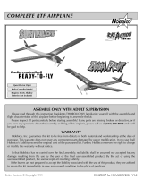
ATTACH THE PROPELLER TO THE AIRPLANE
12
APPLY THE DECALS
Install the propeller in the following order:
1. Disconnect the battery first!
2. Slide the prop on the prop shaft and onto the nut.
3. Slide the Spinner Base onto the prop.
4. Slide the Spinner Insert into the base.
5. Using a pliers or small adjustable wrench, tighten the
Spinner Nut so that the prop is secure on the shaft.
6. Attach the rubber Spinner Cone over the end so it seats
over the Spinner Insert.
Landing Gear Plate Screw
(Cowl shown removed
for clarity)
The front of the Prop
has lettering
Landing Gear Plate
Landing Gear
Prop
Prop Shaft
Spinner
Insert
Spinner Nut
(5.5mm)
Spinner
Base
Spinner
Cone

10
13
Attach the wing to the fuselage
using the four rubber bands
provided. Install the first two, one
on each side from front to back.
Attach the last two criss-cross from
corner to corner.
ATTACH THE WING TO THE FUSELAGE
14
Install and connect the battery. Turn on the transmitter and receiver. Make sure that the propeller
is clear from any obstacles. Hold onto the fuselage and push the start button. The prop should start to
rotate. Turn off the receiver switch to stop the motor.
This section is VERY important and must not be omitted! A model that is not
properly balanced will be unstable and difficult to fly
.
CHECK MOTOR OPERATION
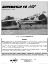
15
The proper balance point is 1-5/8" (42mm) back from the leading edge of the wing. This point is marked
on the underside of the wing with indents as shown. Put your fingertips at the indents and lift the airplane. If
the plane leans forward, add some weight to the tail until it is level. If the plane leans backwards, add weight
to the nose.
If you need to add tail weight, glue a penny to the underside of the tail or cut a slot with a hobby knife
and insert a penny into the slot. Place a piece of tape over the slot to hold the penny in place. If nose weight
is needed, remove the cowl and tape a penny to the inside.
BALANCE THE AIRPLANE
Rubber Bands
Balance Points
Leading Edge
Balance Point
1-5/8¨ (42mm)

The best way to learn how to fly is with the help of a
qualified instructor. In order for you to be successful you
must have a good understanding of how to control the
model before taking off. Please be patient and
thoroughly read all of the following guidelines and
instructions before attempting to fly. If you have any
questions, give us a call at (217) 398-8970 and we will
be glad to help. Contact your local hobby dealer for
flying clubs in your area. If you are not near a hobby
shop, contact the National Academy of Model
Aeronautics (See the front of this book for their address
and phone number) for a list of clubs in your area.
BEFORE FLYING THE SKYRUNNER
1. Find an open area free of buildings, trees, power
lines, people, or any other obstacles. Do not fly in
busy areas such as parks or near highways.
2. For your first several flights, fly only in winds of no
more than 3 miles per hour. After you are comfortable
with the airplane, you can fly in winds that are no
more than 7 miles per hour.
3. Before each flight check the control surfaces.
4. Make sure that the on-board Battery pack is fully
charged and that the transmitter has good (AA)batteries
installed.
5. If others are flying in the same area, make sure that
they are not using the same channel radio system you
are. The back of your transmitter will have a tag with a
color and number (For example:
4 27.145). This is the channel or frequency you
are using.
6. Range check your radio before each flight. Switch on
the transmitter and then the receiver. Do not push the
motor start button during the radio range check. With
the antenna collapsed, walk 50 feet away from the
airplane. If you still have control over the airplane, it is
safe to extend the antenna and fly the airplane.
FLYING THE SKYRUNNER
Install a fully charged battery pack into the
airplane. Turn on the transmitter first and fully extend
the antenna. Next, turn on the receiver switch (Do not
push the motor start button yet!).
Takeoff (Hand launch):
You can launch the airplane yourself, but it is better to
have a friend launch the plane for you. To launch, hold
the airplane by the fuselage directly under the wing
and point it straight into the wind. When the pilot is
ready, push the motor start button. Run a few steps and
gently release the airplane STRAIGHT and LEVEL.
Control the airplane using gradual right and left
rudder to keep the wings level. Use the elevator only
to maintain your current altitude until the plane
reaches full flying speed.IMPORTANT: DO NOT
FORCE THE AIRPLANE INTO GAINING ALTITUDE
BY USING FULL UP ELEVATOR. If you give too much
elevator or try to turn before the plane reaches a good
flying speed, the airplane will stall and possibly crash.
A stall occurs when the airplane is slowed too much
and the wings lose their lift. When this happens, the
plane will either drop its nose or one wing tip, if this
happens to you, don’t panic. It is easy to recover. Just
let the plane lose altitude and regain airspeed. Stalls
are most commonly caused by using too much
up elevator. Be careful, if you allow the plane to stall
too close to the ground, you may crash due to the lack
of altitude for recovery.
IMPORTANT! Remember, your transmitter
controls are always in relationship to the airplane.
11
FL
FL
YING
YING
THE SKYRUNNER
THE SKYRUNNER
Things you’ll need for flying–
• Airplane
• Transmitter
• 8 “AA” Batteries
• Nicd Battery Pack and Charger
Wind
Direction
Incorrect
Correct
Straight
and level with
the ground.
Wind
Direction
IMPORTANT: Launch the plane
level (parallel) with the ground. If it
is launched upwards, the plane will
stall too close to the ground and
will crash.

What this means is that if the plane is coming towards
you and you give right rudder, from your point of view
the plane will go left. But if you were sitting in the
plane, you would see that the plane actually went to
its right as you told it. To help you get acquainted with
this idea, when the plane is coming at you, turn your
body and transmitter to the side while watching the
plane over your shoulder. This will help you to make
the correct control inputs.
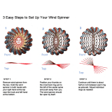
Turns:
For most maneuvers, only small stick movements
are required. Making smooth turns takes lots of
practice. First move the rudder about 1/4 to 1/3 travel.
As soon as the plane begins to bank, release the rudder
back to neutral. Repeat this several times for a nice
continual turn (little turn - neutral, little turn - neutral,
and so on). Once the plane is pointing the direction
you want, give a slight bump (not too much) of
opposite rudder to straighten the plane. NOTE: If you
are flying in winds approaching 7 miles per hour, try to
keep the plane in front of you and upwind. If you let it
wander too far downwind, it may be difficult to fly
back to you.
Once you are comfortable using the rudder to
make turns, you may then begin practicing adding in
the elevator. By using the elevator, you can make
sharper, smoother turns and maintain a desired
altitude. You will notice that when you make a turn
with rudder only, you will lose a little altitude. This is
normal. By adding in a small amount of up elevator,
you can easily keep the plane at the
same height. You will notice that when the plane is
banked, the elevator will help turn the airplane and
will allow make sharper turns.
Flight Trimming:
Once the plane is comfortably in the air, point into
the wind and release the transmitter stick. If the plane
wants to go left or right, adjust the rudder trim to
compensate. If the plane wants to gain or lose altitude,
adjust the elevator trim to compensate. The plane
should be "trimmed" so that it will fly straight and level
when the controls are at neutral.
Flight Time:
With a fully charged battery pack, the motor will
run approximately 4 minutes. This will seem like a
long time when you’re flying. At this point, the
autocut-off unit will turn the motor off, leaving you
plenty of radio power to glide the plane.
Landing:
Once the motor cuts off, prepare to land. Always
land as straight into the wind as possible. You may
need to circle the plane a few times to gradually
descend to the ground. Control your rate of descent
with small amounts of elevator while keeping the
plane level. Remember, without motor power the
airplane will fly slower and stall easier, so do not apply
more than a small amount of up elevator.
Just before touchdown, add more up elevator to
flare the airplane for a smooth touch down. Don’t try
12
Turning using the
Rudder Only
Turning using Rudder
with elevator
Wind

to slow the plane too soon using too much elevator or
you may stall the plane too early. After you walk over
to the plane, turn off the receiver and then the
transmitter.
If you are forced to land with the wind, it will seem
that the rudder and elevator will have less effect on the
airplane and that the plane must land at a higher
speed.
After The Flight:
Unplug and remove the battery. Allow the battery
pack to completely cool before recharging. Check the
plane for any loose connections or control linkages
that might be showing signs of wear. Examine the wing
and fuselage and repair any cracks or wrinkles before
flying again.
Structure:
In the unfortunate event that you may damage your
airplane, repairs are fairly simple and straight forward.
If there are any cracks in the wing or fuselage, apply 6-
minute epoxy to the broken area and hold together
with clear packaging tape. Let the glue cure, leaving the
tape in place for added strength.
After all repairs are completed, recheck the Balance
Point and adjust as needed (see step 14 of the
assembly section. Check the prop to make sure it has
not been damaged. It should point straight ahead and
not up or down or to the side.
Fuse:
If the motor does not turn when the start button
is pushed, check the fuse located inside the fuselage
on the auto cut-off unit. If the fuse is bad, remove the
auto cut-off and remove the fuse. Replace with a new
10 amp fuse.
Control Surfaces: The rudder and elevator on the tail
of the airplane that provide maneuverability to the
airplane.
Dead Stick: A term used to describe unpowered flight
(glide) when the engine quits running.
Elevator: The hinged control surface located at the
trailing edge of the horizontal stabilizer (stab), which
provides control of the airplane and causes it to climb
or dive. The correct direction of control is to pull the
transmitter stick back, toward the bottom of the
transmitter, to climb, and push the stick forward to
dive.
Fuselage: The body of an airplane.
Horizontal Stabilizer: The horizontal tail surface at the
back of the fuselage which provides pitch stability to
the airplane.
Pushrod: A rigid piece of steel wire used to transfer
movement from the servo to the control surface.
Rudder: The hinged control surface located at the
trailing edge of the vertical stabilizer (fin), which
provides control of the airplane and causes it to turn
left or right.
Servo Arm: The removable arm or wheel which
attaches to the servo output shaft and connects to the
pushrod.
Spinner: The nose cone (rubber) which covers the hub
of the propeller.
Vertical Stabilizer (fin): The nonmoving surface that is
perpendicular to the horizontal stabilizer and provides
lateral yaw stability. The rudder is attached to the
trailing edge of the vertical stabilizer.
Wing: The surface that provides lift to the airplane.
13
Wind
Direction
GLOSSAR
GLOSSAR
Y
Y
REP
REP
AIRS
AIRS

Replacement parts for your Skyrunner.
STOCK # DESCRIPTION
HCAA3206 Fuselage
HCAA3207 Wing Set Complete
HCAA3208 Cowling Set
HCAA3209 Plastic Parts
HCAA3211 Battery Cover
HCAG1004 Motor Mabuchi
HCAG1005 Motor Case Set
HCAG1007 Motor Gear Set
HCAM7005 Sanyo Battery 6v
HCAM7006 Auto Cut-off System
HCAP0115 Skyrunner DC Field Charger
HCAQ3001 Propeller (3)
HCAQ3002 Spinner Set
HCAQ3005 Rubber Bands
XConcepts
®
WildFlyer
™
FreeFlight Electric
(XCPA8100)
Includes: Installed Rechargeable Battery, Quick
Battery Charger, Extra Wing, Extra Horizontal &
Vertical Tail Fins, Spare Prop
Requires: 4 "C" cell batteries
In just 5 minutes, pilots as young as 8 years old can
have the WildFlyer electric freeflight plane ready to
hand-launch. There's just two steps to assembly:
attaching the tail section and snapping in the
landing gear. Power for exciting, 1000-foot flights
comes from a preinstalled Sanyo battery, which can
be recharged in only 30-60 seconds by simply
plugging the charger into the plane. Complete,
illustrated instructions cover assembly, charging,
flight testing and flying.
Great Planes
®
Sonic Blast Free Flight
Ducted Fan Jet
(GPMA4000)
You don't need a ton of cash to join the "Jet Set"—
just a Sonic Blast, six "D" batteries and about six
minutes. Since the fan, motor and battery all come
preinstalled, you can complete assembly in about
five minutes. Then it takes just one more minute to
quick-charge the battery...and now you're ready to
fly! Just switch on the motor and give the Sonic Blast
an easy hand-launch. As it climbs, air enters the
fuselage, where a turbo fan compresses it into a
solid column of air power. That's enough to send the
Sonic Blast soaring 100 feet high, over distances
measuring nearly 300 yards!
Great Planes
®
Pro
™
6-Minute Epoxy
GPMR6045
High-quality Pro 6-Minute Epoxy offers enough cure
time to let you position parts correctly—without
making you wait and wait before continuing with
assembly. You'll also get the advantage of strong, lasting
bonds. Includes 9 ounces each of resin and hardener.
Other Gr
Other Gr
eat P
eat P
roducts
roducts
P
P
AR
AR
TS LIST
TS LIST
14

Hobbico
®
AirVista
™
Almost Ready-to-Fly
R/C Trainer
(HCAA2200)
Wingspan: 62 in Wing Area: 685 sq in
Weight: 5.5 lb Wing Loading: 18.5 oz/sq ft
Length: 50 in
Includes FREE video!
Requires: 2-stroke .40 engine & 4-channel radio
Need somebody to guarantee your success before
you'll try a radio-controlled trainer plane? Hobbico
accepts! They're that confident in the revolutionary,
62" span AirVista's supersimple assembly and easy
flight. You can put it together in about 2 hours using
just 2 common household tools. With only a 4-
channel radio, a .40 engine and a few small pieces
of flight gear, you're 100% ready to fly. The plane's
quality matches any professionally built kit...making
it durable AND naturally inclined to fly straight, slow
and steady.
So, as long as you train at an AMA-chartered club
field with a qualified instructor, Hobbico
GUARANTEES you'll succeed—or they'll replace
your AirVista with any other Hobbico trainer of up to
equal value. You can't lose!
Hobbico
®
Power Patrol
™
Electric
Ready-to-Run R/C Command Vehicle
(HCAC0002)
Requires: 7.2V, 6-cell NiCd battery pack, charger &
12 "AA" batteries
The 1/10 scale 2WD Power Patrol comes fully
assembled. Pop in a charged battery pack and you're
ready to move—over dirt, grass, sand, gravel and
other off-road surfaces. Steer any direction, using
two forward speeds and one-speed reverse. A
"jackrabbit" start kicks up the front wheels for a high-
speed wheelie. The included, high-quality radio
gives you total control.
Hobbico
®
M1 Abrams Electric
Ready-to-Run R/C Tank
(HCAC0001)
The 1/10 scale M1 Abrams tank comes with TWO
motors and radio gear factory-installed. It's
immediately ready for battle on any surface, such as
grass, sand and asphalt. You can go forward or
reverse...conquer steep inclines...even execute a 360
turn—while nearly standing still! Realistic details
include a non-motorized, adjustable gun turret and
barrel, and an authentic camouflage color scheme
on the durable polypropylene body.
15

Great Planes Marine
™
Dagger
™
Deep Vee
GPMB1010
Length: 23.25 in Motor: Thrustmaster 550-size (included)
Beam: 7.125 in Requires: 2-channel radio, 6- or 7-cell battery & charger
Styled after hot full-size deep vees, the Dagger electric features extensive factory preassembly: The ABS hull
and deck are prejoined, and the motor and radio box—which has built-in guides for quick receiver and
servo installation—are preinstalled. For all-out, non-stop action, the Dagger's in-line direct drive delivers full
speed without inefficient gears. Trim tabs, stabilizing strakes and an extra-long rudder let you rip through
choppy water and long straightaways at will—or carve the water's surface with sharp, quick "S" turns!
Colorful, durable decals give the Dagger sharp, distinctive looks. Includes motor, micro switch, prop and
display stand.
DuraTrax
®
Maximum ST
™
Ready-to-Run Nitro Truck
(DTXD60XX)
Length: 15 in Front/Rear Track: 9.45 in Height: 7.7 in
Wheelbase: 12.6 in Ground Clearance: 1.9 in
Requires: fuel, glow starter
Take speed, power and durability to the MAX, with the Maximum ST nitro truck from DuraTrax! The
Maximum ST comes ready to run, with radio installed, and an impact-resistant body that's already cut,
trimmed, painted and covered in a clear protective coating. Even "AA" batteries for the radio are included!
This rugged off-roader sports a muscular Torq
™
.12 engine on a sturdy, lightweight chassis with huge, high-
grip monster truck tires. The "Rapid-Tune
™
" shocks permit on-the-fly tension adjustments with the turn of a
screw, and a responsive disc brake system provides reliable stopping power. Another high-tech bonus feature
is the built-in slipper clutch, which helps control "wheel spin" and prevent gear damage. Also included: a
free Engine Starting & Maintenance video!
/