Page is loading ...

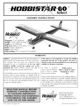
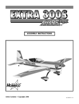
ASSEMBLY INSTRUCTIONS
Entire Contents © Copyright 2004 HCAZ3047 for HCAA2090 V1.0
Wingspan: 61 in [1550mm]
Wing Area: 708 sq in [45.7 dm
2
]
Weight: 7.5 - 8.5 lb [3400 - 3850g]
Wing Loading: 24 - 28oz/sq ft [73 - 85 g/dm2]
Length: 51.5 in [1310mm]
Radio: Four-channel with 5 servos
Engine: .50 - .75 cu in [8 - 12cc] two-stroke,
.70 - .91 cu in [11. 5 - 15cc] four-stroke
Hobbico
®
guarantees this kit to be free from defects in
both material and workmanship at the date of purchase.
This warranty does not cover any component parts
damaged by use or modification. In no case shall
Hobbico’s liability exceed the original cost of the
purchased kit. Further, Hobbico reserves the right to
change or modify this warranty without notice.
In that Hobbico has no control over the final assembly or
material used for final assembly, no liability shall be
assumed nor accepted for any damage resulting from the
use by the user of the final user-assembled product. By
the act of using the user-assembled product, the user
accepts all resulting liability.
If the buyer is not prepared to accept the liability
associated with the use of this product, the buyer is
advised to return this kit immediately in new and unused
condition to the place of purchase.
To make a warranty
claim, send the defective
part or item to Hobby
Services at this address.
Include a letter stating your name, return shipping address, as
much contact information as possible (daytime telephone
number, fax number, e-mail address), a detailed description
of the problem and a photocopy of the purchase receipt.
Upon receipt of the package the problem will be evaluated
as quickly as possible.
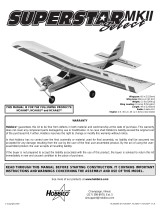
READ THIS MANUAL BEFORE
STARTING CONSTRUCTION.
IT CONTAINS IMPORTANT
INSTRUCTIONS AND WARNINGS
CONCERNING THE ASSEMBLY
AND USE OF THIS MODEL.
WARRANTY
Hobby Services
3002 N. Apollo Dr. Suite 1
Champaign IL 61822
USA
1610 Interstate Drive
Champaign, Illinois
(217) 398-8970 ext. 2
SUKHOI SU31
SUKHOI SU31
.50 - .91
.50 - .91
ARF
ARF
™

2
TECHNICAL UPDATES . . . . . . . . . . . . . . . . . . .2
AMA . . . . . . . . . . . . . . . . . . . . . . . . . . . . . . . .2
SAFETY PRECAUTIONS . . . . . . . . . . . . . . . . . .2
HARDWARE AND ACCESSORIES . . . . . . . . . . .3
ADDITIONAL ITEMS REQUIRED . . . . . . . . . . .3
Optional Supplies and Tools . . . . . . . . . . . . .4
IMPORTANT BUILDING NOTES . . . . . . . . . . .4
KIT INSPECTION . . . . . . . . . . . . . . . . . . . . . .5
KIT CONTENTS . . . . . . . . . . . . . . . . . . . . . . . .5
ORDERING REPLACEMENT PARTS . . . . . . . . .6
REPLACEMENT PARTS LIST . . . . . . . . . . . . . . .6
PREPARATIONS . . . . . . . . . . . . . . . . . . . . . . .6
ASSEMBLE THE WING . . . . . . . . . . . . . . . . . . .7
Install the Ailerons . . . . . . . . . . . . . . . . . . . .7
Install the Aileron Servos and Pushrods . . . . .7
Join the Wings . . . . . . . . . . . . . . . . . . . . . . .9
ASSEMBLE THE FUSELAGE . . . . . . . . . . . . . . .11
Install the Stab, Elevators and Rudder . . . . .11
Install the Landing Gear . . . . . . . . . . . . . . .12
Install Engine, Fuel Tank & Throttle Servo . . .13
Mount the Cowl . . . . . . . . . . . . . . . . . . . . .15
Install the Radio System . . . . . . . . . . . . . . .17
FINISHING TOUCHES . . . . . . . . . . . . . . . . . .19
GET THE MODEL READY TO FLY . . . . . . . . . .19
Check the Control Directions . . . . . . . . . . .19
Set the Control Throws . . . . . . . . . . . . . . . .19
Balance the Model (C.G.) . . . . . . . . . . . . . .20
Balance the Model Laterally . . . . . . . . . . . .20
PREFLIGHT . . . . . . . . . . . . . . . . . . . . . . . . . .21
Identify Your Model . . . . . . . . . . . . . . . . . .21
Charge the Batteries . . . . . . . . . . . . . . . . . .21
Balance Propellers . . . . . . . . . . . . . . . . . . .21
Ground Check . . . . . . . . . . . . . . . . . . . . . .21
Range Check . . . . . . . . . . . . . . . . . . . . . . .21
ENGINE SAFETY PRECAUTIONS . . . . . . . . . .22
AMA SAFETY CODE . . . . . . . . . . . . . . . . . . .22
CHECK LIST . . . . . . . . . . . . . . . . . . . . . . . . .23
FLYING . . . . . . . . . . . . . . . . . . . . . . . . . . . . .23
Takeoff . . . . . . . . . . . . . . . . . . . . . . . . . . . .24
Flight . . . . . . . . . . . . . . . . . . . . . . . . . . . . .24
Landing . . . . . . . . . . . . . . . . . . . . . . . . . . .24
For the latest technical updates or manual
corrections to the Hobbico Sukhoi SU31 visit the
Hobbico web site at www.hobbico.com. Open the
“Airplanes” link, then select the Hobbico Sukhoi
SU31 .50 -.91 ARF. If there is new technical
information or changes to this model a “tech
notice” box will appear in the upper left corner of
the page.
We urge you to join the AMA (Academy of Model
Aeronautics) and a local R/C club. The AMA is the
governing body of model aviation and membership is
required to fly at AMA clubs. Though joining the AMA
provides many benefits, one of the primary reasons to
join is liability protection. Coverage is not limited to
flying at contests or on the club field. It even applies to
flying at public demonstrations and air shows. Failure
to comply with the Safety Code (excerpts printed in the
back of the manual) may endanger insurance coverage.
Additionally, training programs and instructors are
available at AMA club sites to help you get started the
right way. There are over 2,500 AMA chartered clubs
across the country. Contact the AMA at the address or
toll-free phone number below:
5151 East Memorial Drive
Muncie, IN 47302-9252
Tele. (800) 435-9262
Fax (765) 741-0057
Or via the Internet at:
http://www.modelaircraft.org
IMPORTANT!!!
Two of the most important things you can do to
preserve the radio controlled aircraft hobby are to
avoid flying near full-scale aircraft and avoid flying
near or over groups of people.
1. Your Hobbico Sukhoi SU31 should not be
considered a toy, but rather a sophisticated, working
model that functions very much like a full-size airplane.
Because of its performance capabilities, the Hobbico
Sukhoi SU31, if not assembled and operated correctly,
could possibly cause injury to yourself or spectators
and damage to property.
2. You must assemble the model according to the
instructions. Do not alter or modify the model, as
doing so may result in an unsafe or unflyable model. In
a few cases the instructions may differ slightly from the
photos. In those instances the written instructions
should be considered as correct.
Protect your model, yourself &
others... Follow these Important
Safety Precautions
AMA
TECHNICAL UPDATES
TABLE OF CONTENTS

3
3. You must take time to build straight, true and strong.
4. You must use an R/C radio system that is in first-
class condition, and a correctly sized engine and
components (fuel tank, wheels, etc.) throughout the
building process.
5. You must correctly install all R/C and other
components so that the model operates correctly on
the ground and in the air.
6. You must check the operation of the model before
every flight to insure that all equipment is operating and
that the model has remained structurally sound. Be
sure to check clevises or other connectors often and
replace them if they show any signs of wear or fatigue.
7. If you are not an experienced pilot or have not
flown this type of model before, we recommend
that you get the assistance of an experienced pilot
in your R/C club for your first flights.
8. While this kit has been flight tested to exceed
normal use, if the plane will be used for extremely
high stress flying, the modeler is responsible for
taking steps to reinforce the high stress points.
9. WARNING: The cowl included in this kit is made
of fiberglass, the fibers of which may cause eye,
skin and respiratory tract irritation. Never blow into
the cowl to remove fiberglass dust, as the dust will
blow back into your eyes. Always wear safety
goggles, a particle mask and rubber gloves when
grinding, drilling and sanding fiberglass parts.
Vacuum the parts and the work area thoroughly
after working with fiberglass parts.
Remember: Take your time and follow the
instructions to end up with a well-built model.
This is a partial list of items required to finish the
Hobbico Sukhoi SU31 that may require planning or
decision making before starting to build. Order
numbers are provided in parentheses.
RADIO EQUIPMENT
❏ Four channel radio
❏ Four 54 oz-in servos and one 30 oz-in servo
❏ Two 6” [150mm] servo extensions
(HCAM2701 for Futaba)
❏ Y-harness (HCAM2751 for Futaba)
❏ 500 mAh battery or greater
ENGINE RECOMMENDATIONS
We have installed both a two-and a four-stroke engine
in our prototypes. The two-stroke engine with a
standard muffler or with most Pitts style mufflers
requires much of the cowl to be cut away, while the
four-stroke maintains most of the integrity of the cowl.
If a more “scale“ look is desired we recommend the
four-stroke engine over the two-stroke.
50 - .75 cu in [8 - 12cc] two-stroke,
.70 - .91 [11. 5 - 15cc] four-stroke
❏ R/C foam rubber (1/4” [6mm] - HCAQ1000,
or 1/2” [13mm] - HCAQ1050)
❏ 1/2 oz. [15g] Thin Pro
™
CA (GPMR6001)
❏ 1 oz. [30g] Medium Pro CA+ (GPMR6008)
❏ Pro 30-minute epoxy (GPMR6047)
❏ Pro 6-minute epoxy (GPMR6045)
❏ Drill bits: 1/16” [1.6mm], 5/64” [2mm], 1/8”
[3.2mm], 3/16” [4.8mm].
❏ #1 Hobby knife (HCAR0105)
❏ #11 blades (5-pack, HCAR0211)
❏ Top Flite
®
MonoKote
®
sealing iron (TOPR2100)
❏ CA applicator tips (HCAR3780)
❏ R/C-56 canopy glue (JOZR5007)
❏ Threadlocker thread locking cement
(GPMR6060)
ADDITIONAL ITEMS REQUIRED
HARDWARE & ACCESSORIES
We, as the kit manufacturer, provide you with a
top quality, thoroughly tested kit and
instructions, but ultimately the quality and
flyability of your finished model depends on how
you build it; therefore, we cannot in any way
guarantee the performance of your completed
model, and no representations are expressed or
implied as to the performance or safety of your
completed model.

OPTIONAL SUPPLIES AND TOOLS
Here is a list of optional tools mentioned in the
manual that will help you build the Hobbico
Sukhoi SU31.
❏ 2 oz. [57g] spray CA activator (GPMR6035)
❏ CA debonder (GPMR6039)
❏ Epoxy brushes (6, GPMR8060)
❏ Mixing sticks (50, GPMR8055)
❏ Mixing cups (GPMR8056)
❏ Curved-tip canopy scissors for trimming plastic
parts (HCAR0667)
❏ Robart Super Stand II (ROBP1402)
❏ 18” x 24” [460 x 610mm] Builder’s Cutting
Mat (HCAR0455)
❏ Hobbico Duster
™
can of compressed air
(HCAR5500)
❏ Masking tape (TOPR8018)
❏ Denatured alcohol (for epoxy clean up)
❏ Switch & Charge Jack Mounting Set
(GPMM1000)
❏ Rotary tool such as Dremel
®
❏ Rotary tool reinforced cut-off wheel
(GPMR8200)
❏ Servo horn drill (HCAR0698)
❏ AccuThrow
™
Deflection Gauge (GPMR2405)
❏ CG Machine
™
(GPMR2400)
❏ Precision Magnetic Prop Balancer
™
(TOPQ5700)
·
When you see the term test fit in the
instructions, it means that you should first
position the part on the assembly without using
any glue, then slightly modify or custom fit the
part as necessary for the best fit.
·
Whenever the term glue is written you should
rely upon your experience to decide what type
of glue to use. When a specific type of adhesive
works best for that step, the instructions will
make a recommendation.
·
Whenever just epoxy is specified you may use
either 30-minute (or 45-minute) epoxy or 6-
minute epoxy. When 30-minute epoxy is
specified it is highly recommended that you
use only 30-minute (or 45-minute) epoxy,
because you will need the working time and/or
the additional strength.
·
Photos and sketches are placed before the step
they refer to. Frequently you can study photos
in following steps to get another view of the
same parts.
·
The stabilizer and wing incidences and engine
thrust angles have been factory-built into this
model. However, some technically-minded
modelers may wish to check these
measurements anyway. To view this
information visit the web site at
www.hobbico.com and click on “Technical
Data.” Due to manufacturing tolerances which
will have little or no effect on the way your
model will fly, please expect slight deviations
between your model and the published values.
METRIC CONVERSIONS
COMMON ABBREVIATIONS
Fuse = Fuselage
Stab = Horizontal Stabilizer
Fin = Vertical Fin
LE = Leading Edge
TE = Trailing Edge
LG = Landing Gear
Ply = Plywood
" = Inches
mm = Millimeters
SHCS = Socket Head Cap Screw
1/64" = .4mm
1/32" = .8mm
1/16" = 1.6mm
3/32" = 2.4mm
1/8" = 3.2mm
5/32" = 4mm
3/16" = 4.8mm
1/4" = 6.4mm
3/8" = 9.5mm
1/2" = 12.7mm
5/8" = 15.9mm
3/4" = 19mm
1" = 25.4mm
2" = 50.8mm
3" = 76.2mm
6" = 152.4mm
12" = 304.8mm
15" = 381mm
18" = 457.2mm
21" = 533.4mm
24" = 609.6mm
30" = 762mm
36" = 914.4mm
To convert inches to millimeters,
multiply inches by 25.4 (25.4mm = 1")
IMPORTANT BUILDING NOTES
4

5
11
12
13
14
1
2
3
4
5
6
7
8
9
10
KIT INSPECTION
KIT CONTENTS
Before starting to build, take an inventory of this kit to make sure it is complete, and inspect the parts to
make sure they are of acceptable quality. If any parts are missing or are not of acceptable quality, or if you
need assistance with assembly, contact Product Support. When reporting defective or missing parts, use
the part names exactly as they are written in the Kit Contents list.
Hobbico Product Support • 3002 N Apollo Drive, Suite 1 • Champaign, IL 61822
Telephone: (217) 398-8970, ext. 2 • Fax: (217) 398-7721
E-mail: [email protected]
Items photographed
1. Fuselage & Cowl
2. Fuel tank
3. Dummy engine
4. Left wing
5. Landing gear
6. Wheels
7. Wheel pants
8. Tail wheel assembly
9. Belly pan
10. Canopy
11. Right wing
12. Stab & elevators
13. Fin & Rudder
14. Engine Mount
Qty
2 15x15x15mm hardwood block
2 15x15x10mm hardwood block
2 155mm length of Velcro
®
2 3mm plywood wing joiner
1 Plywood wing bolt plate
5 Nylon control horns and plates
17 Hinges
5 Nylon clevises
4 Faslinks
2 4 x 40mm machine screw
2 4 x 35mm machine screw
4 4 x 25mm machine screw
4 4 x 19mm machine screw
4 4 x 15mm machine screw
10 4mm flat washer
8 4mm lock washers
2 4mm nuts
3 3 x 5mm machine screw
2 4mm wheel collar
4 2 x 20mm machine screw
Qty
6 2 x 15mm machine screw
3 2 x 7mm sheet metal screw
1 screw lock connector
1 2mm thumb nut
1 2mm washer for screw-lock
connector
1 300mm nylon pushrod
3 2 x 710 mm pushrod wire
1 1mm wire
4 4mm blind nuts
4 3 x 12mm cowl mounting bolts
1 6 x 6 x 127mm balsa stick
1 2.5” (approximately 64mm)
red plastic spinner
1 400mm fuel tubing
6 4mm lock nuts
5 Silicone clevis retainers
2 2 x 80mm pushrod wire
Parts not photographed

Replacement parts for the Sukhoi SU 31 ARF are
available using the order numbers in the
Replacement Parts List that follows. The fastest,
most economical service can be provided by your
hobby dealer or mail-order company.
To locate a hobby dealer, visit the Hobbico web site at
www.hobbico.com. Choose “Where to Buy” at the
bottom of the menu on the left side of the page. Follow
the instructions provided on the page to locate a U.S.,
Canadian or International dealer. If a hobby shop is not
available, replacement parts may also be ordered from
Tower Hobbies at www.towerhobbies.com or by
calling toll free (800) 637-6050.
Parts may also be ordered directly from Hobby Services
by calling (217) 398-0007, or via facsimile at
(217) 398-7721, but full retail prices and shipping and
handling charges will apply. Illinois and Nevada
residents will also be charged sales tax. If ordering via
fax, include a Visa
®
or MasterCard
®
number and
expiration date for payment.
Mail parts orders and payments by personal check
to:
Hobby Services
3002 N Apollo Drive, Suite 1
Champaign IL 61822
Be certain to specify the order number exactly as
listed in the Replacement Parts List. Payment by
credit card or personal check only; no C.O.D.
If additional assistance is required for any reason
contact Product Support by e-mail at
[email protected], or by telephone at
(217) 398-8970.
Order
Number Description How to purchase
HCAA3630 . . . . . Wing . . . . . . Hobby Supplier
HCAA3631 . . Fuse/belly pan. . . Hobby Supplier
HCAA3633 . . . Tail Surfaces . . . Hobby Supplier
HCAA3632. . . . . . Cowl . . . . . . Hobby Supplier
HCAA3635. . . . . Canopy . . . . . Hobby Supplier
HCAA3636 . . Landing Gear . . . Hobby Supplier
HCAA3634 . . Wheel Fairings. . . Hobby Supplier
HCAA3637 . . Dummy Engine . . Hobby Supplier
Missing pieces. . . . . . . . . . . . . . Product Support
Instruction manual. . . . . . . . . . . Product Support
Full-size plans . . . . . . . . . . . . . . . Not available
1. If you have not done so already, remove the
major parts of the kit from the box and inspect for
damage. If any parts are damaged or missing,
contact Product Support at the address or telephone
number listed in the “Kit Inspection” section on
page 5.
2. Remove the tape and separate the ailerons and
flaps from the wing and the elevators from the stab.
Use a covering iron with a covering sock on high
heat to tighten the covering if necessary. Apply
pressure over sheeted areas to thoroughly bond the
covering to the wood.
When ready to fly, you'll need some additional
equipment to fuel the plane and start the engine.
The most important items include an electric starter,
12 volt battery, or chicken stick, fuel pump (electric
or hand-crank), fueling lines and fittings and a 1.5
volt glow plug igniter. Your flight instructor will
probably let you share his equipment for a while,
but eventually you'll need your own. Visit your local
hobby dealer or see the Hobbico catalog for a full
selection, descriptions and pricing.
PREPARATIONS
REPLACEMENT PARTS LIST
ORDERING REPLACEMENT PARTS
6

INSTALL THE AILERONS
Do the right wing first so your work matches the
photos the first time through.
❏❏1. Install a hinge into each of the four hinge
slots in the aileron. Be sure the slit in the hinge is
perpendicular to the leading edge of the aileron.
❏❏2. Apply six drops of thin CA to the top and
bottom of each hinge waiting a few seconds
between drops to allow the CA to soak in. Do not
use CA accelerator. After the CA has fully hardened,
test the hinges by pulling on the aileron.
❏❏3. Locate the opening for the servo on the bottom
of the wing. Cut the covering from the opening.
❏❏4. On the top of the wing locate the 1/2”
[13mm] hole and cut the covering away.
❏ 5. Repeat steps 1 - 4 for the left wing.
INSTALL THE AILERON SERVOS AND PUSHRODS
❏ 1. Installing the servos in the wing will require
the use of one 6” [152mm] servo extension for each
aileron. One Y-harness connector is required and is
used to allow the aileron servos to plug into one slot
in your receiver. You may have a computer radio
that allows you to plug the servos into separate slots
and mix them together through the radio transmitter.
If you choose to mix them with the radio rather than
the Y-harness, refer to the instructions with your
particular brand of radio. Attach the servo extension
to the aileron servo. Secure the connectors together
using a large piece of heat shrink tubing or tape.
❏❏2. Located in the wing in the servo compartment,
a string is taped to the wing skin. Tie the string to the end
of the servo wire. Pull the servo wire through the wing
with the string. Feed the servo wire out the hole in the
top of the wing center section. Tape the servo wire to
the wing to prevent it from falling back into the wing.
ASSEMBLE THE WING
7

❏❏3. Install the servo into the wing. Center the
servo and install a servo arm as shown.
❏❏4. Position a nylon control horn on the aileron as
shown in the sketch, aligning it with the servo. Mark the
location for the screw holes. Drill through the marks you
made with a 1/16” [1.6mm] drill bit, drilling through the
aileron. Secure the control horn to the aileron with two
2 x 20mm [3/4”] machine screws and the nylon
mounting plate.
❏❏5. Locate a 2 x 102mm [4”] pushrod wire
threaded on one end. Screw a nylon clevis onto the
threaded end of the wire 20 full turns. Install a
silicone clevis keeper onto the clevis and then install
the clevis in the second hole from the end of the
aileron control horn.
❏❏6. Be sure the aileron servo is centered.
Enlarge the second outermost hole in the servo arm
with a Hobbico Servo Horn Drill (or a #48 or 5/64”
[2mm] drill bit). Center the aileron and align the wire
pushrod with the hole in the end of the servo arm.
Using a marker, mark the location where the wire
aligns with the hole in the servo arm. On that mark
make a 90 degree bend. From the bend measure an
additional 3/16” [4.8mm], then cut off the excess
pushrod wire.
❏❏7. Install the wire into the hole in the servo
arm using a nylon FasLink as shown in the sketch.
❏ 8. Repeat steps I - 7 for the left wing panel.
Correct Incorrect
8

JOIN THE WINGS
❏ 1. Locate two hardwood wing joiners. Glue them
together with 6-minute epoxy, forming one 1/4” [6mm]
wing joiner. Set the joiner aside until the glue cures.
❏2. Test fit the joiner into both wing halves, making
sure that it is not too tight. Sand the joiner as needed
to get a good fit.
❏ 2. Apply 30-minute epoxy to the wing joiner, the
joiner pocket in both wing panels and the root rib of
each wing panel. Push the wing panels together and
hold them in place with masking tape. Before the glue
cures, set the wing flat on your bench and measure the
dihedral. The distance from the top of the bench to the
center of the wing as measured at the wing tip should be
approximately 2-3/8” [60mm]. Block the wingtip up
while the glue cures. Note: Due to production
techniques there may be some variance in the actual
dihedral of each model. 1/4” [6mm] more or less than
this dimension is acceptable.
❏ 3. Set the wing aside allowing the glue to cure.
❏ 4. Cut the covering from the wing bolt holes on
both the top and bottom of the wing.
❏5. Place the plywood wing bolt mounting plate in
position on the bottom of the wing, centered on the
wing bolt holes. Using a fine-tip, felt-tip marker,
trace the outline of the plate onto the wing. Use a
sharp #11 hobby knife or use the Expert Tip that
follows to cut the covering from the wing along the
lines you have marked. Use care to cut only into the
covering and not into the wood.
2-3/8" [60mm]
9

Use a soldering iron to cut the covering from the stab.
The tip of the soldering iron doesn't have to be sharp, but
a fine tip does work best. Allow the iron to heat fully.
Use a straightedge to guide the soldering iron at a rate
that will just melt the covering and not burn into the
wood. The hotter the soldering iron, the faster it must
travel to melt a fine cut. Peel off the covering.
❏ 6. Glue the plywood wing bolt plate to the wing.
❏7. From the top of the wing, drill through the two
wing bolt holes and through the plywood wing bolt
plate using a 5/32” [4mm] drill bit.
❏8. Mount the wing to the fuselage with two 4 x 35mm
[1-3/8”] machine screws and two 4mm washers.
❏ 9. Cut the covering from the wing bolt holes in
the belly pan. Place the belly pan onto the bottom of
the wing, aligning it with the fuselage. Mark the
outline of the belly pan onto the fuselage with a fine-
tip, felt-tip marker.
❏10. Just inside the lines you have made, cut away a
1/4” [6mm] strip of covering. Remove a 1/4” [6mm] strip
from the front and rear of the wing as well.
❏11. Glue the belly pan to the wing. Tape the belly
pan in place while the glue cures. Once cured,
remove the wing from the fuselage.
❏ 12. If you will be using a “Y” harness for the
ailerons, attach the “Y” harness to the aileron servos.
Secure the connectors together using a large piece of
heat shrink tubing, tape or other method.
HH
HH
oo
oo
tt
tt
TT
TT
ii
ii
pp
pp
How to cut covering from balsa
10

INSTALL THE STAB, ELEVATORS AND RUDDER
❏ 1. Cut the covering away from the stab opening
on both sides of the fuselage. On the left side of the
fuselage cut away the covering from the elevator and
rudder pushrod openings. On the right side cut the
covering from the elevator and antenna openings.
❏2. Mount the wing to the fuselage the test fit the stab
into the opening in the back of the fuselage. Stand back
and look at the stab in relation to the wing. The stab
should be parallel with the wing. If not, sand the stab
saddle until the stab and wing align.
❏3. Measure the distance from the tip of the stab to
the tip of each wing. Adjust the position of the stab
until both are equal.
❏ 4. Once you are satisfied with the fit and
positioning of the stab, use a fine, felt-tip marker and
trace the outline of the fuselage onto the top and
bottom of the stab. Cut the center section of the
covering from the top and bottom of the stab using
the same technique used for the wing.
❏ 5. When satisfied with the fit of the stab, use thin
CA with a CA applicator tip to wick glue into the stab
saddle. Apply the glue to the top, bottom and both
sides of the fuselage. Allow the glue to fully cure
before moving. After the glue has cured remove the
wing from the fuselage.
“Hint”: Do not use any accelerator. This will most likely
cause the glue to get a white haze on the fuselage and
stab. Allow the plane to sit for approximately 5 minutes
until the glue is completely cured.
❏ 6. Install the two elevator halves using the same
method used for the ailerons. Once you are satisfied
with the positioning of the elevators, glue them in place
with thin CA the same as was done on the ailerons.
ASSEMBLE THE FUSELAGE
11

❏ 7. Install the fin into the slot in the top of the
fuselage. Use a fine, felt-tip marker and trace the
outline of the fuselage onto the fin. Cut the covering
from the fin using the same technique used on the
wing and stab.
❏ 8. Apply epoxy on the fin and in the slot in the
fuselage. Check to make sure the fin is perpendicular to
the stab. If necessary, use masking tape to pull the fin
into position. Set the fuselage aside until the glue cures.
❏9. Insert three hinges into the rudder. Then slide the
rudder onto the fin. Apply thin CA onto the hinges the
same as was done with the other control surfaces.
This completes the installation of the tail surfaces.
You will finish the installation of the control horns
and pushrods when you do the radio installation.
INSTALL THE LANDING GEAR
❏ 1. Attach the landing gear to the fuselage with
four 4 x 15mm [9/16”] machine screws. Apply a
couple of drops of thread locker to the bolts before
installing them into the fuselage.
❏2. Assemble the wheel and wheel pant as shown.
Do this for both wheels.
4 x 40mm
MACHINE
SCREW
4mm
NUT
4mm
LOCK NUT
12

❏3. Slide the black nylon mounting flange onto the
tail wheel wire. Then bend the wire as shown.
❏ 4. Make a 90 degree bend 1” [25mm] from the
pivot point of the tail wheel wire.
❏5. Place the tail wheel assembly onto the bottom of
the fuselage and mark the location where the wire will
go through the rudder. Drill a 1/16” [1.6mm] hole into
the bottom of the rudder; slide the wire into the bottom
of the rudder. Drill a 1/16” [1.6mm] hole into the
fuselage through each of the mounting holes in the
nylon mounting flange. Secure the flange to the fuselage
with three 2 x 7mm [5/16”] sheet metal screws.
INSTALL ENGINE, FUEL TANK & THROTTLE SERVO
❏ 1. The top of the engine mount can be identified
by the angled bevel. Be sure when mounting the
engine in the following steps that you mount the
engine on the top of this rail.
❏ 2. Mount the engine to the two engine mount
halves. The distance from the front of the engine thrust
washer to the firewall should be 5-1/4” [133mm]. Place
the engine on one of the mounts. Mark the location for
the mounting holes onto the engine mount rail. On the
marks, drill through the rail with a 5/32” [4mm] drill.
Secure the engine to the rail with 4 x 25mm [1”]
machine screws and 4mm lock nuts. Do this for both
engine mount halves.
13

❏ 3. The engine will be mounted to the firewall on
its side (see photograph at step 7). On the firewall
there are reference marks. On the engine mount
there are also reference marks.
❏ 4. Align the reference marks of the engine mount
with the lines on the firewall and center the sides of the
engine mount with the reference lines on the firewall.
❏ 5. With the engine properly positioned mark the
engine mount holes onto the firewall. Remove the
engine from the firewall and drill through each of the
marks with a 3/16” [4.8mm] drill.
❏ 6. Position a 4mm blind nut behind one of the
holes you drilled in the firewall. Insert a 4mm [5/32”]
machine screw and washer into the hole, threading
it into the 4mm blind nut. Tighten the bolt until the
blind nut is pulled tight against the backside of the
firewall. Remove the bolt and repeat this for each of
the three remaining holes.
❏ 7. Install the engine mount to the firewall with
four 4 x 19mm [3/4”] machine screws, 4mm lock
washer and 4mm flat washer.
❏8. Assemble the fuel tank as shown. If you will be
using a fuel valve (not included) for filling the tank
rather than filling the tank by removing the line from
the carburetor, install it in the fuel line following the
instructions included with the valve.
❏ 9. Install the fuel tank into the fuselage, and
through the hole in the firewall. From the 6 x 6 x
127mm [5”] balsa stick, cut the stick to fit and glue
it in place behind the tank.
FUEL TANK
PRESSURE
TAP TO
MUFFLER
TO NEEDLE
VALVE
FIREWALL
SILICONE
FUEL LINE
FUEL CLUNK
FUEL
PIPE
14

❏10. Install fuel tubing from the tank to the engine and
muffler, following the instructions with your engine.
❏11. Drill a 5/64” [2mm] hole through the firewall in
line with the carburetor on your engine. Insert the 2 x
300mm [12”] nylon throttle tube guide through the
hole and into the radio compartment. Apply glue to the
end of the nylon pushrod, gluing it to the firewall.
❏12. Mount the throttle servo on the left side of the
servo tray as shown. (Refer to the picture on page 18,
“Install the Radio System”, step 7 for the placement
of all of the servos in the fuselage). Install the screw-
lock connector onto the servo arm, securing it with a
2mm washer and nut. Apply a drop of thread locker
to the nut to prevent it from coming loose. Slide the
1mm pushrod wire into the tube and through the
hole in the screw-lock connector. Install the throttle
arm onto the z-bend on the end of the pushrod wire.
When the pushrod wire is secure on the throttle arm,
secure the throttle wire to the screw-lock connector
with a 2 x 2mm [1/16”] bolt.
MOUNT THE COWL
❏ 1. On the right side of the fuselage, mark the
location for the cowl mounting blocks. For the top
mounting block measure from the front of the fuselage
back 1-5/8” [40mm] and make a line. Measure up from
the bottom of the fuselage 3-1/2” [89mm] and make a
line intersecting the other line. Place a 15 x 15 x 10mm
[5/8” x 5/8” x 3/8”] hardwood block at the intersection
of the two lines. Trace the outline of the block onto the
fuselage. At the location of the block, cut the covering
from the fuselage.
At the front of the fuselage, measure up from the
bottom of the fuselage 3/4” [19mm] and make a
mark. Place a 15 x 15 x 15mm [5/8” x 5/8” x 5/8”]
block on this line, turning the block so the corners
are aligned with the front of the fuselage. Trace the
outline of the block and then cut the covering from
the fuselage. Glue both blocks to the fuselage with
6-minute epoxy. Repeat this procedure for the
blocks on the left side of the fuselage.
❏ 2. Next you need to slip the cowl onto the
fuselage. Depending on which engine you have
chosen to install, you may not be able to slide the
cowl over the engine. Most 2-stroke engines are
short enough to allow the cowl to slip over the
engine without interference. The O.S.
®
.91 is a bit too
tall for the cowl to slide over but will fit if you
remove the valve cover.
❏3. For the next step you may find it helpful to have
an assistant. Position the cowl so the distance from
15

the firewall to the front of the cowl is 5-3/8”
[136mm]. This dimension will properly space the
engine when using the spinner included with this kit.
If you are using a different spinner or no spinner you
may need to position the cowl further forward or
back to properly position the cowl. Place your
spinner and propeller on the engine to be sure you
have the proper spacing required.
❏ 4. Double-check to be sure you have the proper
spacing for the cowl and that the cowl is centered on
the engine. Have your assistant hold the cowl while
you mark the location for the cowl mounting screws.
(The cowl mounting blocks are easily visible from
the back of the cowl.)
Begin on the right side of the fuselage first. Drill a 3/32”
[2.4mm] hole through the cowl and into the top cowl
mounting block. Install a 3mm cowl mounting screw
into the cowl. Double check the positioning of the
cowl and then drill the bottom hole. Repeat this for the
left side of the fuselage, checking the position of the
cowl after each screw is installed.
❏5. Remove the cowl mounting screws and the cowl.
Put a couple of drops of thin CA into each of the screw
holes to harden the threads. Allow the glue to cure.
❏ 6. Re-install the cowl onto the front of the
fuselage. On the cowl, mark the location for the
glow plug, needle valve, muffler or any part of the
engine that conflicts with the cowl. Using a rotary
tool, begin cutting small portions of the cowl,
making the holes progressively larger until the cut-
out matches your particular engine installation.
❏ 7. Cut the center of the plastic dummy engine to
fit around the front of the engine. Leave plenty of
clearance between the dummy engine and the
engine thrust washer. The spinner will cover any gaps
between the two. Mark the location of the engine
cylinder and then cut away this area from the
dummy engine. Paint the dummy engine with a fuel
proof paint. We painted the louvers a light gray and
the engine flat black.
❏8. Slip the dummy engine into the cowl and then
install the cowl onto the fuselage. Position the
dummy engine, centering it with the engine. Using
medium CA glue with a micro-tip on the bottle, tack
glue the dummy engine to the cowl. Once the
dummy engine is secure to the cowl, remove the
cowl and permanently glue the dummy engine in
place by applying a bead of glue to the back of the
dummy engine from inside the cowl.
16

INSTALL THE RADIO SYSTEM
1. Locate three 2 x 685mm [27”] pushrod wires
threaded on one end. Screw a nylon clevis onto the
threaded end of the wires 20 full turns. Install a
silicone clevis keeper onto the clevises. Connect a
nylon control horn onto each of the two clevises.
Install the clevis in the second hole from the end of
the control horn.
❏ 2. Slide two of the wires with clevises attached
into the openings shown in the photographs.
❏ 3. Position the control horns on the elevators,
positioning them the same way as you did with the
ailerons. Mark the location for the screw holes. Drill
through the marks you made with a 1/16” [1.6mm]
drill bit, drilling through the elevator. Secure the
control horn to the aileron with two 2 x 15mm [5/8”]
machine screws and the nylon mounting plate.
❏4. Insert the third rod into the remaining opening on
the left side of the fuselage. Connect the control horn to
the clevis and attach the control horn to the rudder in
the same way you installed them to the elevators.
❏5. Install the rudder servo into the servo tray at the
position shown. Mark the location for the servo
mounting screws. Drill a 1/16” [1.6mm] hole through
the marks, drilling through the plywood tray. Insert and
then remove one of the servo mounting screws supplied
with your radio into each of the four holes you have
drilled. Apply a couple of drops of thin CA to each of
the holes to harden the threads. After the glue has cured
permanently mount the servo.
❏ 6. Be sure the rudder servo is centered. Enlarge
the outermost hole in the servo arm with a Hobbico
Servo Horn Drill (or a #48 or 5/64” [2mm] drill bit).
17

Center the rudder and align the wire pushrod with
the hole in the end of the servo arm. Use a fine, felt-
tip pen to mark the wire where it crosses the holes in
the servo arm. On that mark make a 90 degree bend.
From the bend measure an additional 3/16” [4.8mm]
and then cut off the excess pushrod wire. Install a
nylon Faslink to the wire and servo arm.
❏ 7. Install the elevator servo into the servo tray.
Position it in line with the elevator pushrods. Mount
the servo using the same procedure used for the
rudder servo.
❏ 8. Make a bend in the elevator pushrod wires as
shown in the photo above.
❏ 9. Screw a 2.5 x 5mm [3/16”] bolt with a small
amount of threadlocker into two 4mm [5/32”] wheel
collars. Slide the wheel collars onto the wires. Align
the elevators. Tighten the set screws against the
wires. Cut the excess wire.
❏10. Be sure the elevator servo is centered. Enlarge the
outermost hole in the servo arm with a Hobbico Servo
Horn Drill (or a #48 or 5/64” [2mm] drill bit). Center the
elevators and align the wire pushrod with the hole in the
end of the servo arm. Using a marker, mark the location
where the wire aligns with the hole in the servo arm. On
that mark make a 90 degree bend. From the bend
measure an additional 3/16” [4.8mm] and then cut off
the excess pushrod wire. Install a nylon Faslink to the
wire and servo arm.
❏ 11. Install the battery and receiver as shown.
Place 1/4” thick foam under the receiver and battery,
holding it in place with the Velcro material included
with the kit.
❏12. Use an arm cut from a servo horn to make an
antenna strain relief as shown. Insert the receiver
antenna into the white antenna tube. Hold it to the
fuselage by placing a small rubber band around the
tail wheel and the end of the antenna.
❏ 13. Install the radio switch to the side of the
fuselage. Connect the battery to the switch and
secure the ends of the leads with heat shrink tubing,
tape or some other method for securing the leads.
18

❏ 1. If you wish to install a pilot, permanently glue
it in place in the cockpit.
❏2. Trim the canopy on the molded cut lines. Glue
the canopy to the fuselage with RC 56 canopy glue.
❏3. Install the propeller that is best suited to your engine.
CHECK THE CONTROL DIRECTIONS
❏1. Turn on the transmitter and receiver and center
the trims. If necessary, remove the servo arms from
the servos and reposition them so they are centered.
Reinstall the screws that hold on the servo arms.
❏2. With the transmitter and receiver still on, check
all the control surfaces to see if they are centered. If
necessary, adjust the clevises on the pushrods to
center the control surfaces.
❏ 3. Make certain that the control surfaces and the
carburetor respond in the correct direction as shown
in the diagram. If any of the controls respond in the
wrong direction, use the servo reversing in the
transmitter to reverse the servos connected to those
controls. Be certain the control surfaces have
remained centered. Adjust if necessary.
SET THE CONTROL THROWS
❏ Use a Great Planes AccuThrow (or a ruler) to
accurately measure and set the control throw of each
control surface as indicated in the chart that follows. If
your radio does not have dual rates, we recommend
setting the throws at the low-rate setting.
NOTE: The throws are measured at the widest part
of the elevators, rudder and ailerons.
IMPORTANT: The Hobbico Sukhoi SU31 has
been extensively flown and tested to arrive at the
throws at which it flies best. Flying your model at
these throws will provide you with the greatest
chance for successful first flights. If, after you
have become accustomed to the way the
Hobbico Sukhoi SU31 flies, you would like to
change the throws to suit your taste, that is fine.
However, too much control throw could make
the model difficult to control, so remember,
“more is not always better.”
Recommended control surface throws
High Rate Low Rate
ELEVATOR 5/8” up 1/2” up
[16mm] [13mm]
5/8” down 1/2” down
RUDDER 1-1/2” right 1” right
[38mm] [25mm]
1-1/2” left 1” left
AILERONS 3/4” up 1/2” up
[19mm] [13mm]
3/4” down 1/2” up
4-CHANNEL
TRANSMITTER
TRANSMITTER
4-CHANNEL
TRANSMITTER
4-CHANNEL
TRANSMITTER
4-CHANNEL
GET THE MODEL READY TO FLY
FINISHING TOUCHES
19

BALANCE THE MODEL (C.G.)
At this stage the model should be in ready-to-fly
condition with all of the systems in place including
the engine, landing gear, covering and paint, and the
radio system.
❏ 1. Use a felt-tip pen or 1/8” [3mm]-wide tape to
accurately mark the C.G. on the top of the wing on
both sides of the fuselage. The C.G. is located
3-15/16” [100mm] back from the leading edge of the
wing at the fuselage side.
❏2. With the wing attached to the fuselage, all parts
of the model installed (ready to fly) and an empty
fuel tank, place the model upside-down on a Great
Planes CG Machine, or lift it upside-down at the
balance point you marked.
❏ 3. If the tail drops, the model is “tail heavy” and
the battery pack and/or receiver must be shifted
forward or weight must be added to the nose to
balance. If the nose drops, the model is “nose heavy”
and the battery pack and/or receiver must be shifted
aft or weight must be added to the tail to balance. If
possible, relocate the battery pack and receiver to
minimize or eliminate any additional ballast
required. If additional weight is required, nose
weight may be easily added by using a “spinner
weight” (GPMQ4645 for the 1 oz. [28g] weight, or
GPMQ4646 for the 2 oz. [56g] weight). If spinner
weight is not practical or is not enough, use Great
Planes (GPMQ4485) “stick-on” lead. A good place
to add stick-on nose weight is to the firewall (don’t
attach weight to the cowl—it is not intended to
support weight). Begin by placing incrementally
increasing amounts of weight on the bottom of the
fuse over the firewall until the model balances. Once
you have determined the amount of weight required,
it can be permanently attached. If required, tail
weight may be added by cutting open the bottom of
the fuse and gluing it permanently inside.
Note: Do not rely upon the adhesive on the back of
the lead weight to permanently hold it in place.
Over time, fuel and exhaust residue may soften the
adhesive and cause the weight to fall off. Use #2
sheet metal screws, RTV silicone or epoxy to
permanently hold the weight in place.
❏ 4. IMPORTANT: If you found it necessary to add
any weight, recheck the C.G. after the weight has
been installed.
BALANCE THE MODEL LATERALLY
❏1. With the wing level, have an assistant help you
lift the model by the engine propeller shaft and the
bottom of the fuse under the TE of the fin. Do this
several times.
❏ 2. If one wing always drops when you lift the
model, it means that side is heavy. Balance the
airplane by adding weight to the other wing tip. An
airplane that has been laterally balanced will track
better in loops and other maneuvers.
This is where your model should balance for the
first flights. Later, you may wish to experiment by
shifting the C.G. up to 1/4” [6mm] forward or
1/8” [3mm] back to change the flying
characteristics. Moving the C.G. forward may
improve the smoothness and stability, but the
model may then require more speed for takeoff
and make it more difficult to slow for landing.
Moving the C.G. aft makes the model more
maneuverable, but could also cause it to
become too difficult to control. In any case, start
at the recommended balance point and do not
at any time balance the model outside the
specified range.
More than any other factor, the C.G. (balance point)
can have the greatest effect on how a model flies,
and may determine whether or not your first flight
will be successful. If you value this model and wish
to enjoy it for many flights, DO NOT OVERLOOK
THIS IMPORTANT PROCEDURE. A model that is
not properly balanced will be unstable and
possibly unflyable.
20
/