FläktGroup eQ Hygienic design Installation and Maintenance Manual
- Type
- Installation and Maintenance Manual

Contents Page
Hygienic version..................................……………………………….. 2
Delivery.........................................……………………………………..... 2
Safety precautions..........................………………………………...... 2
Mounting on the floor....................………………………………........ 3
Suspending from the ceiling................…………………………….. 4
To install the drainage water trough......……………………….... 5
To clean the casing...........................……………………………….... 5
To clean the finned-tube coils............…………………………...... 5
To clean the fan..............................…………………………………..... 5
To clean the rotary heat exchanger........………………………... 5
To clean the plate heat exchanger.........…………………………. 6
To disinfect the air handling unit............………………………….. 6
EQGA AND EQGB HYGIENIC VERSION,
CODE SUFFIX I = 3 AND 4
ASSEMBLY AND MAINTENANCE INSTRUCTIONS

EQGA AND EQGB, HYGIENIC VERSION, CODE SUFFIX I = 3 AND 4
Assembly and maintenance instructions
2
FläktGroup DC_8946GB 20220421_R1 Specifications are subject to change without further notice
DELIVERY
The hygienic air handling unit is delivered in accordance with
one of the following alternatives:
• As one delivery unit, i.e. one factory-assembled block unit.
• As one delivery unit, i.e. one factory-assembled unit mounted
on a base frame.
• Several block units, which must be connected to form one unit
on site.
SAFETY PRECAUTIONS
Lifting and transport of air handling units, mounting them on a
base frame and fitting them with support feet, the docking of
blocks, safety precautions and inspection prior to commissioning
are specified in the General instructions, Safety Precautions,
8658 GB.
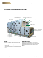
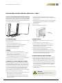
Window for
easy inspection
Hygienically approved
non-metallic components
Thermal insulation to class T3
Condensation insulation to class TB3
Aluzinc or stainless casing
Casing to leakage
class L2
Bag filters, HEPA- or
carbon filters
Wall mounted fan or floor
mounted fan with integrated
or fully sealed fan beams
without sharp edges
Cleanable floor
without grooves
Provision for coil
with cleanable drip
tray
Components which
are simple to clean,
for example coils,
rotary heat exchang-
ers and plate heat
exchangers
Large inspection
spaces
HYGIENIC VERSION

EQGA AND EQGB, HYGIENIC VERSION, CODE SUFFIX I = 3 AND 4
Assembly and maintenance instructions
3
FläktGroup DC_8946GB 20220421_R1 Specifications are subject to change without further notice
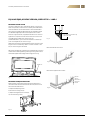
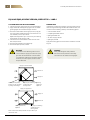
MOUNTING ON THE FLOOR
The floor on which the unit is placed must be flat, to ensure pro-
blem-free operation. Check the floor carefully to avoid distortion
of the unit and thus ensure that the doors will not be difficult to
open and close. EQAZ-05 adjustable feet are available to allow
for individual height adjustment of the EQAZ-04 base frame.
Place the support washer (supplied) under the foot as shown in
Figure 8. It is important to make sure that the unit is level. If the
air handling unit includes unit sections that are
provided with drains, space must be available for a water trap
(such as the EQAZ-08) as shown in Fig. 9.
Adjustment of the lateral and longitudinal position of the air hand-
ling unit is best carried out by means of a roller crowbar or the
like, as shown in Figures 10 and 11.
N.B! The air handling unit should slope 2 % towards the inspection
side to allow for drainage during cleaning. Flushing water can be
collected in EQWZ-02 drainage water trough (accessory).
MOUNTING ON ADJUSTABLE FEET
Mount the feet spacing them evenly along the side beams if
more than 4 feet are to be fitted. If 4 feet are used, fit one foot at
each end of the side beams.
To adjust the adjusting screw:
1) Back off the locking nut (A).
2) Adjust the height with set screw (B).
3) Lock the locking nut (A).
Block unit without base frame
Block unit on EQAZ-04 base frame
2%
Fig. 7
Fig. 8
EQWZ-02
EUGA Fig 8
Free space for water trap
= min. 150 mm
15 mm
gap in
the end of
the base
frame
Fig. 9
Fig. 10
Fig. 11

EQGA AND EQGB, HYGIENIC VERSION, CODE SUFFIX I = 3 AND 4
Assembly and maintenance instructions
4
FläktGroup DC_8946GB 20220421_R1 Specifications are subject to change without further notice
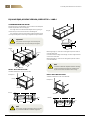
SUSPENSION FROM THE CEILING
Place the unit on a stand made on site as shown in the examples
below. Suspend the unit from hangers.
The larger units must be fitted with EQAZ-29 floor grating so
that service personnel can enter the air handling unit.
The stand must also be constructed so that the bottom panels
are supported by either traversing or longitudinal support beams.
HEAVY-DUTY INSTALLATION
Suitable installation for unit sizes 005-216
Example 1
Important!
The position of the hangers can be easily ad-
justed with the stand according to the figure.
N.B!
The tensile strength verification must be issued
by an authorized HVAC installation engineer.
Retaining flange A – max. 35 mm along the inspection side on
unit sizes 005-090.
Cut and remove the edge of the flange ”A” at the hinge locations
on unit sizes 005-090.
Retaining flange A – max. 75 mm along the inspection side on
unit sizes 081-216.
HEAVY-DUTY INSTALLATION
Suitable installation for unit sizes 005-216
Example 2
max. 1,5 m
min. 800
Hanger
Clamp
View A
Hanger
cc max 600cc max 600
2%
View A
Hanger
A
N.B!
If the unit is fitted with a EQWZ-02 water drainage
trough, the edge of the flange (A) should only be
by the corner frame members of the casing.
View B
View B
cc max 600cc max 600
2%

EQGA AND EQGB, HYGIENIC VERSION, CODE SUFFIX I = 3 AND 4
Assembly and maintenance instructions
5
FläktGroup DC_8946GB 20220421_R1 Specifications are subject to change without further notice
TO INSTALL THE DRAINAGE WATER TROUGH, EQWZ-02
The drain water trough is supplied as a loose part and should be
fitted after the air handling unit has been docked. Place the drain
water trough onto the mounting angle bracket and fasten it with
the screws supplied (see illustration).
TO CLEAN THE CASING
Carry out the following before cleaning the interior of the casing:
• Remove the filters
• Remove the withdrawable filter frame
• Remove the withdrawable sound attenuating baffles
• Remove the withdrawable droplet separators
• Remove anti-skid devices, if fitted
• Remove withdrawable drip trays
CLEANING
1. Vacuum-clean surfaces to remove loose dust.
2. Apply suitable dirt and degreasing agent such as cold de-
greasing agent on interior surfaces.
3. Flush the surfaces clean with clean water after a few
minutes. N.B! Do not use a high-pressure spray gun.
The flushing water is collected in the drain water trough which
can be connected to a drain or a collection vessel.
CLEANABLE COILS FOR HYGIENE APPLICATIONS
All coils with hygiene fins are fully cleanable according to the
standards VDI3803 and VDI6022. This means that the coil can
be cleaned with a high-pressure water system right through
the core. The cleaning nozzle used for coils with a fin pitch of
2.0-2.5 mm and deeper than six tubes is THD Power Clean
manufactured by TECHNISCHER HYGIENE DIENST GMBH
(E-mail: [email protected], web: www.thd.info). If the coil is six tubes
deep or less, an ordinary nozzle can be used.
1. Make sure that no sensitive equipment, either inside or out-
side the unit, can be harmed by the water.
Be extra careful not to damage the filter. If the unit has an
empty section (EQTC), use the special drip plate to protect
the rest of the unit.
2. Clean the coil with a high-pressure cleaner. If the coil is
deeper than six tubes, a THD Power Clean is needed to ensure
a full cleanability.
3. Point the nozzle at a 45-degree angle to have a free passage
for the water jet through the coil. Make sure that the water
penetrates the coil.
4. Remove all dirt.
5. Dry all surrounding parts in the unit.
CLEANING THE FAN
1. Open the inspection panel if the centrifugal fan section
has one.
2. Vacuum-clean the fan to remove dry dust.
3. Apply suitable dirt and degreasing agent such as cold
degreasing agent on the fan blades, motor (degree of
protection IP54) and other surfaces.
4. Flush with clean water after a few minutes. N.B!
Do not use a high-pressure spray gun.
5. If the fan casing is equipped with a means for drainage,
the water will run out on the floor of the unit casing and be
collected in the drainage water trough. Otherwise, wipe
the interior of the fan casing dry with a cloth.
TO CLEAN THE ROTARY HEAT EXCHANGER
1. Vacuum-clean the surface of the rotor to remove dry dust.
2. Apply suitable dirt and degreasing agent such as cold
degreasing agent onto the rotor surface and other surfaces.
3. Flush after a few minutes with a high-pressure spray gun.
Aim the jet of water at right angles towards the rotor struc-
ture. The spray nozzle should appropriately be held approx.
50 mm away from the face surface of the rotor. Suitable
pressure: up to 80 bar.
4. Vacuum-clean to remove water or blow surfaces clean with
compressed air.
Important!
Do not use methyl ethyl ketone, aceton or
corrosive liquids.

EQGA AND EQGB, HYGIENIC VERSION, CODE SUFFIX I = 3 AND 4
Assembly and maintenance instructions
6
FläktGroup DC_8946GB 20220421_R1 Specifications are subject to change without further notice
TO CLEAN THE PLATE HEAT EXCHANGER
1. Vacuum-clean the surface of the rotor to remove dry dust.
2. Apply suitable dirt and degreasing agent such as cold de-
greasing agent onto the heat exchanger surfaces.
3. Flush after a few minutes with a high-pressure spray gun.
The spray nozzle should be held 3-5 cm from the face sur-
face. Suitable pressure: up to 80 bar.
EQRZ-01 flushing water tray is an accessory for collecting
flushing water on the supply air side.
4. Vacuum-clean to remove water or blow surfaces clean
with compressed air.
5. Clean the flushing water tray and drip tray.
6. Clean the droplet separator, if fitted.
DISINFECTION
If disinfection is required, for example, in hospital environments,
after finishing the cleaning procedure described the above, the
surfaces can be treated e.g. with any of the following agents:
• 5 % chlorinated solution
• 6 % hydrogen dioxide solution
• Hydrogen dioxide mist
• 10 -15 % isopropyl alcohol
• Hydrogen peroxide
Apply the cleaning agent on all the surfaces inside the air hand-
ling unit.
Warning!
If a nozzle of a size delivering 2 litres/min at
7 bar is used, the supply pressure to the spray
gun must not exceed 25 bar since the nozzle
is inclined at an angle of 20 º to the face surface,
and if the pressure is higher, the face surface
may be deformed.
Warning!
Wear protective gloves and protective
face mask. See the protection and safety
instructions for the relevant cleaning agent.
Supply air at the bottom
Supply air uppermost
Extract air
Extract air
Supply air
Supply air
The droplet separator,
if fitted, can be removed
by lifting and folding it.
Drip tray for collecting
condensate and
flushing water
Flushing
water tray
EQRZ-01
Flushing water tray
EQRZ-01
Drip tray for collecting
condensate and
flushing water
Make sure that the damper blades are open when you
flush them clean
-
 1
1
-
 2
2
-
 3
3
-
 4
4
-
 5
5
-
 6
6


FläktGroup eQ Hygienic design Installation and Maintenance Manual
- Type
- Installation and Maintenance Manual
Ask a question and I''ll find the answer in the document
Finding information in a document is now easier with AI
Related papers
-
FläktGroup eQ MASTER General Operating instructions
-
-
-
-
-
-
-
-
-
Other documents
-
 Gallo Acoustics Droplet Installation guide
-
 SystemAir HHFlex Installation, Operation And Maintenance Instructions
-
Wolf KGW 250 Installation And Maintenance Instructions Manual
-
-
Multitech 1777.8/7-10 G3 User manual
-
Condair 1507183-E HP Series HVAC Installation guide
-
Trane CCE-Compact Series Installation Operation & Maintenance
-
VESPA S 50 4T 4V (2008) User manual
-
-
Trox X-CUBE X2 Installation guide

