Page is loading ...

HP Series
Installation and
Operation Manual
Includes installation, operation
maintenance and troubleshooting
information for your HP Series
humidifier
1507183-E| 17 JUN 2016
Important: Read and save these instructions. This guide to be left with equipment owner.

Thank you for choosing Condair.
Proprietary Notice
This document and the information disclosed herein are proprietary data of Condair Ltd. Neither this document
nor the information contained herein shall be reproduced, used, or disclosed to others without the written
authorization of Condair Ltd., except to the extent required for installation or maintenance of recipient’s
equipment.
Liability Notice
Condair does not accept any liability for installations of humidity equipment installed by unqualified personnel
or the use of parts/components/equipment that are not authorized or approved by Condair.
Copyright Notice
Copyright 2019, Condair Ltd. All rights reserved.
INSTALLATION DATE (MM/DD/YYYY)
MODEL #
SERIAL #
CYLINDER #
INSTALLATION DATE (MM/DD/YYYY)
MODEL #
SERIAL #
CYLINDER #

Contents
2 Introduction
2 About HP
3 Receiving and Unpacking Equipment
3 Absorption Distances
3 Components
6 Multiple Zones
7 Water Quality
17 Installation
18 Important Notes on Installation
20 Pre-Installation
23 Construction of a Wet Duct Section
24 Pump Module
27 Mounting the Pump Station
28 Water Installation
31 HP Manifolds
37 Mist Eliminator
43 Startup, Operation, and
Maintenance
44 Initial Commissioning and Startup
37 HP High Pressure Atomizing
Humidifier Start-up Checklist
50 Operation
59 Setting the Unit Into Daily
Operation
60 Inspection During Operation
61 Shutting Down the Unit
62 Maintenance
65 Preventative Replacement Parts
69 Troubleshooting
72 Warranty

1 | HP Series Installation Manual
CAUTION: Servicing
Disconnect main power before any servicing.
The plumbing and electrical compartments contain high voltage components and
wiring. Access should be limited to authorized personnel only.
During and following operation of the humidifier, the steam and components in
contact with the steam such as the blower pack, steam lines, steam distributors,
and condensate lines can become hot and can burn if touched.
Condair does not accept any liability for installations of humidity equipment
installed by unqualified personnel or the use of parts/components/equipment
that are not authorized or approved by Condair.
CAUTION: Electrical
All electrical work should be done according to local and national electrical code.
Electrical connection to be performed by a licensed electrician.
CAUTION: Plumbing
Plumbing to be performed by a licensed plumber.
Drain water from humidifier can be very hot. Do not drain to public sink.
All plumbing work should be done according to local plumbing code.
CAUTION: Installation
Do not mount on hot surfaces.
Do not mount in area where freezing can occur.
Do not mount on vibrating surface.
Do not mount on floor.
Regardless of selecting on/off or modulating control method, Condair
humidifiers must have a closed circuit across its on/off security loop control
terminal to operate. Condair highly recommends the use of a duct high limit
humidistat.

HP Series Installation Manual | 2
Introduction
HP (Adiabatic Humidification System)
Congratulations on the purchase of your Condair HP humidification system. This system was
designed to be efficient and reliable, and is manufactured from high quality materials to provide
long trouble free operation. In order for the system to operate as intended it must be installed
properly.
This guide details the design, installation, commissioning, operation, and troubleshooting of the
HP system. Please take the time to familiarize yourself with this guide before beginning to
ensure that the system is installed the way it was designed. This ensures a long and trouble
free life of the humidifier.
About HP (Adiabatic Humidification System)
The HP (High Pressure) system is designed to be installed inside an AHU or duct system to
humidify air to a desired relative humidity. Proper humidity levels have been shown to be
important for health and comfort of occupants. Maintaining proper humidity is also important
for many industrial and manufacturing processes.
The HP system uses a series of nozzles to spray a very fine mist of water droplets into an air
stream. During this process the air absorbs moisture increasing its relative humidity levels. As
the water droplets evaporate, they absorb some energy in the form of heat from the air. This
loss of heat causes the air temperature to drop, resulting in a phenomenon known as adiabatic
cooling.
The HP adiabatic system has 2 effects:
The relative humidity of the air increases (humidification)
The temperature of the air falls (adiabatic cooling)
Humidification of the air is the main goal of the HP system. The cooling of the air is secondary
and is frequently beneficial since it is ‘free’ cooling. In cases where air-cooling is un-desired,
preheating of the air is required.
In general a HP system has the following advantages over other humidification technologies:
Low frequency of maintenance, since there are few moving or expendable parts.
Replacing components is quick and requires minimal system disassembly.
A ‘free’ air-cooling benefit from water extracting latent heat from the air.

3 | HP Series Installation Manual
Receiving and Unpacking Equipment
Check packing slip to ensure ALL material has been delivered.
All material shortages are to be reported to Condair within 48 hours from receipt of goods.
Condair assumes no responsibility for any material shortages beyond this period.
Inspect shipping boxes for damage and note on shipping waybill accordingly.
After unpacking, inspect equipment for damage and if damage is found, notify the shipper
promptly.
All Condair products are shipped on an F.O.B. factory basis. Any and all damage, breakage or
loss claims are to be made directly to the shipping company.
Absorption Distances
An important consideration in the planning of a HP system is the absorption distance, or the
distance it takes for the droplets to evaporate inside the HVAC system. The absorption distance
is relative to the air velocity, temperature, atmospheric pressure, and the amount of water in the
incoming air. In applications where space is limited, such as in an air-handler, precautions
should be taken to prevent the wetting of sensitive components downstream.
Components
Condair Supplied
Condair will supply the following components:
1 High pressure pump skid
2 Valve block assembly and cables
3 Nozzle manifolds and mounting hardware
4 10 ft. of high pressure hose (optional 6.5 ft., 16.5 ft., or 33 ft. of high pressure hose for
piping)
5 10 ft. of anti-chafe spiral hose (optional)
6 Installation manual, installation drawing with mounting dimensions, and tubing diagram.
7 Mist eliminator (optional)
8 Air proving switch (optional)
9 High limit humidistat (optional)
10 Humidistat (optional)

HP Series Installation Manual | 4
Field Supplied
The Installer is responsible for supplying the following:
1 Electrical disconnects
2 All electrical wiring
3 High pressure piping between pump skid and manifolds
4 Flex hose
5 P-traps
6 Drain funnels
7 Wet duct section (drain pans, wall sections, sealants, fasteners)
8 Pump skid vibration dampening
9 Electricity, water, and airflow

5 | HP Series Installation Manual
2
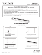
Figure 1: Typical HP System Installation
Humidifier Components:
1 Step Valves MV REG1, MV REG2, and MV REG3
3 Nozzle Manifold
4 Mist Eliminator
5 Flushing Valve MV REG5
Pump Station Components:
6 High Pressure Pump
7 Control Panel, with Touch Screen
8 High Pressure Flexible Hose
9 UV-light system (Option)
Multiple Zones
Oftentimes a single pump package will be used to serve different ducts or zones. In this case
each duct will have its own set of manifolds, valve controller and valve block making it fully

HP Series Installation Manual | 6
independent of the other zones. The pump should be sized to handle the full flow capacity of all
zones combined to ensure reliable operation.
Care must be taken when laying out the piping between the pump and the valve blocks at each
zone to prevent vibration transmission or water hammering effects. The piping should be
securely supported using appropriate cushion clamps (by others) and long straight runs should
be avoided.
Figure 2: Typical Installation with Master/Slave Configuration
All units must be located at the same elevation.
The maximum length of high pressure piping from the pump station to the last Slave unit must not
exceed 200 ft.

7 | HP Series Installation Manual
Water Quality
Water used with the Condair HP system must be very pure. Dissolved solids, and impurities
contained in the water will precipitate out when the water evaporates, causing dust and
minerals to be deposited into ducts, and/or the humidified space. Dusting can have adverse
effects on filters, fans, heating and cooling coils, human health, and may promote corrosion and
bacteria growth in ducts.
For this reason only Reverse Osmosis (RO) or De-Ionized (DI) water can be used with a Condair
HP humidification system. DI water is very aggressive, in applications where DI water is used all
components (including wet section of ducting and drains) must be constructed from stainless
steel.
If a water treatment system is required, the Condair HP RO pump station is available and
includes an integrated RO system built directly onto the HP pump skid.
To ensure that the HP nozzles do not become blocked or damaged over time, the following
conditions should also be met:
Table 1 : Water Quality Requirements
Quality
Requirement
Water Supply:
Drinking Water Quality / RO Water
Conductivity:
5-1000 μS/cm
Silt Index:
Max. 3.0
KMn04:
Max. 10 mg/l
NTU:
Max. 1.0
Temperature:
Max. 59°F (15°C)
TDS:
Max. 625 mg/l
Fe:
Max. 0.05 mg/l
Mn:
Max. 0.05 mg/l
Hardness (Max.):
Max. 5 gpg (5º dH)
Free Chlorine (Max.):
Max. 1 mg/l

HP Series Installation Manual | 8
Component Overview
Pump Station
Figure 3: HP Pump Station
Figure 4: HP Flow Diagram

9 | HP Series Installation Manual
Part Specification
D
Drain
F
Filter 1μ
FR
Water meter (option)
G1
Pressure gauge 0-145 psi (0-10 bar)
G2
Pressure gauge 0-145 psi (0-10 bar)
G3
Pressure gauge 0-1958 or 0- 2320 psi (0-135 or 0-160 bar)
K1
Check Valve
K2
Check Valve
M1
Motor
MV1
Solenoid Valve
MV5
Valve for flushing
MV REG 1
Valve for nozzle strings
MV REG 2
Valve for nozzle strings
MV REG 3
Valve for nozzle strings
P1
High pressure pump
FD
Frequency converter (option)
PT
Pressure transmitter for frequency converter
PS
Pressure switch
R
Pressure reduction valve
T
Thermostat
UV
UV light tube and transformer (option)
V1
Test water tap 1/8”
Pump Station Details
High-pressure pump station.
All components exposed to water are made of corrosion resistant material. The hoses are
drinking water approved high pressure hoses, stainless steel braided or high-pressure hoses in
dimension 1/4" or 3/8”.The system is fitted on a frame and all components are assembled,
tested, and ready to use.
Pump Station: The water-lubricated high pressure stainless steel pump is directly mounted
to the electric motor and operates at a pressure of 435 to 1015 psi (30 - 70 bar).

HP Series Installation Manual | 10
Table 2 : Technical Specifications
HP100
HP200
VFD
HP300
HP500
HP500
VFD
HP800
HP800
VFD
HP1300
VFD
Capacity, l/h*
120
200
318
528
500
948
800
1300
Weight, kg (lb)
50-65
(110-
143)
50-65
(110-
143)
55-70
(121-
154)
65-80
(143-
176)
55-70
(121-
154)
75-90
(165-
198)
65-80
(143-
176)
75-90
(165-
198)
Dimensions l x w
x h, in
25.9 x
19.7 x
51.1
25.9 x
19.7 x
51.1
25.9 x
19.7 x
51.1
25.9 x
19.7 x
51.1
25.9 x
19.7 x
51.1
25.9 x
19.7 x
51.1
25.9 x
19.7 x
51.1
25.9 x
19.7 x
51.1
Water supply, bar
1-4
1-4
1-4
1-4
1-4
1-4
1-4
1-4
Sound pressure
level, db(A)
<80
<80
<80
<80
<80
<80
<80
<80
Electrical
connection
220-240 / 380-415 / 3 / 60Hz
Installed effect:
kW – Pump
0.50
0.80
1.1
1.5
1.2
2.2
2.4
3.5
Pipe diameter –
inlet, “RG
3/8
3/8
3/8
3/8
3/8
3/8
3/8
3/8
The pump is protected against dry running by a pressure switch that stops the system if water
pressure drops. The high-pressure pump is protected against overheating by a temperature
circuit that measures the current temperature in the pump.
Control unit: the control unit consists of the touch display and PLC. A power board, for control of
the high pressure pump and connection terminals for power supply. The power board has an
alarm switch (NC).
Optionally the control unit can be equipped with a remote operating and fault indication print, a
conductivity monitoring and a BMS gateway for the integration into a building management
system (BMS).
The pump station is electrically wired at the factory. At the installation site, the power supply,
the humidity controller or humidity sensor, the remote operating and fault indication (option),
the external safety chain and the step valves must be electrically connected to the control unit.

11 | HP Series Installation Manual
Humidifier Unit
Figure 5: HP Humidifier Unit
1 Nozzle manifold mounting rails
2 Nozzle manifold
3 Spray nozzles
4 Flushing valve MV5 working pressure (option)
5 Step valve MV REG3 (4/7)
6 Step valve MV REG2 (2/7)
7 Step valve MV REG1 (1/7)
8 High-pressure hose from pump station
9 Water drain after nozzles
10 Open drain funnel (by others)
11 Mist Eliminator/Droplet Separator (option or by others)
12 Water drain after humidifier unit
13 P-Trap (by others, height adapted to duct pressure)

HP Series Installation Manual | 12
14 Separation element humidifier unit
15 (min. height: 3 cm, sealed towards the duct floor and the duct walls)
16 Drain hose from flush valve MV5
Nozzle Unit
The nozzle unit consists of several nozzle pipes, which are equipped with the necessary number
of nozzles (system-specific). The individual nozzle pipes are divided into three different spray
circuits (1/7, 2/7 and 4/7). The spray circuits are connected via a high pressure hoses to the
corresponding step valves (either directly or via a distribution blocks).
Mist Eliminator
The installation of a mist eliminator is the customers responsibility. An optional Condair
mist eliminator is available for the Condair HP.
Note regarding the Condair mist eliminator: Due to the special surface finish of the mist
eliminator material, the Condair mist eliminator will reach peak performance about 4-8 weeks
after the initial installation (time depending on the water quality).

13 | HP Series Installation Manual
Figure 6: HP System Layout, Stand Alone System

HP Series Installation Manual | 14
Figure 7: HP System Layout, Master/Slave System

15 | HP Series Installation Manual
General
The pump is driven by a 3-phase motor. The pump speed is controlled from 1000 rpm to 3500
rpm by a frequency controller VFD.
The control system consists of a PLC unit, which controls water treatment and adjusts humidity
in the duct. Adjustment is carried out by means of a special proportional regulator, which
activates the necessary number of steps in relation to the current humidity requirement.
A flushing function is included, which ensures hygienic operation and prevents standing water in
the system. If one of the nozzle pipes has been inactive for 30 minutes, the control panel will
trigger a rinse pulse lasting two seconds, this ensures continual water movement within the
system.
The control signal comes from an analogue 0-10 volt signal. It is possible to choose between
two different modes for this signal:
1 Humidity control – The humidity is measured against the relevant input and the control then
calculates how many steps to activate in order to achieve the required level of humidity.
2 Direct capacity - The required capacity is transferred directly from a BMS system.
Hour counters are incorporated into the control unit. One hour counter that indicates the
pump’s running time to be used for setting service intervals, one hour counter for the pump and
one hour counter for each of the steps, which summarizes the period of time where each step is
active.
Control
With stand-alone systems (master configuration) the control unit is built into the pump station.
The control unit features a separate power supply, a control/humidity signal input, connectors
for the external safety chain and relay connectors for the remote operation and fault indication
(option). In addition, the control unit incorporates the frequency converter for the control of the
high pressure pump.
With master/slave systems, each slave is equipped with a separate control unit. Each control
unit features a separate power supply, a control/humidity signal input, connectors for the
external safety chain and relay connectors for the remote operation and fault indication
(option). A bus cable connects each slave control unit to the control unit of the master system
which controls the high pressure pump.
Humidification
The control of the humidification system is established via an external P/PI controller, or the PID
controller built into the control unit.
As standard, the HP features 7-Stage valve control as outlined in the figure below. An additional
step valve is available as an option, and increases the total number of stages to 15.

HP Series Installation Manual | 16
Figure 8: 7-Stage Valve Control
Monitoring of high pressure pump
The supply pressure and pump temperature are continuously monitored. The HP pump
automatically stops if one of these values is outside the admissible range. A respective error
message appears in the display.
In addition, the control unit of the pump station and the salve control units can be equipped
with a remote operating and fault indication board. Thus the following operating conditions can
be displayed over the appropriate relays: “Error”, “Humidification”, “Maintenance” and “Unit
on”.

17 | HP Series Installation Manual
Installation
/