Page is loading ...

Vorlage Montageanleitungen_Umschlag 13.11.12 10:21 Seite 1
W
olf GmbH • Postfach 1380 • D-84048 Mainburg • Tel.+49 ( 0) 8751/74-0 • Fax +49 (0) 8751/74-1600 • Internet: www.wolf-heiztechnik.d
e
Part no.: 3040530_201503 Subjecttomodications
GB
Installation and Maintenance Instructions
Air handling unit KG Standard
(Translation of the original)

2 3040530_201503
Contents
Contents .............................................................................Page
Reference symbols / Safety instructions ................................... 3
Standards .................................................................................. 4
Delivery / Handling .................................................................... 5
Installation information.......................................................... 6-11
Electrical connection........................................................... 11-13
Commissioning ................................................................... 14-17
Maintenance ....................................................................... 18-20
Frost protection........................................................................ 20
Checklist .................................................................................. 21
Notes ..................................................................................22-23
Order-specicappliancedetails,suchasweights,dimensions,
noisedata,spareparts,energydata,etc.,canbefoundinthe
order datasheets.
Original WOLF spare parts can be obtained quickly by
faxing +49 (0) 8751/74-1574, and stating the order number
(onthetypeplate).

3040530_201503 3
Referencesymbols/Safetyinstructions
These installation, operating and maintenance instructions apply only to Wolf KG
Standard air handling units.
Before installation, carefully read and observe these "Installation, operating and
maintenance instructions - Wolf air handling units KG Standard".
The installation instructions should be considered an integral part of the unit supplied,
and should be retained in an easily accessible location.
Failure to observe the installation and operating instructions voids any Wolf warranty.
General information
Referencesymbols
Thefollowingsymbolsareusedintheseinstallationandmaintenanceinstructions.
This important information concerns personal safety, as well as operational
reliability.
"Safetyinstructions"areinstructionswithwhichyoumustcomplyexactly,to
preventinjuryandmateriallosses.
Danger through 'live' electrical components!
Please note: Turn OFF the ON/OFF switch before removing the casing.
Never touch electrical components or contacts when the ON/OFF switch is in the
ONposition.Thiswouldresultinariskofelectrocutionthatmayleadtoinjury
or death.
Themainsupplyterminalsare'live'evenwhentheON/OFFswitchisintheOFF
position.
"Pleasenote"indicatestechnicalinstructionsthatyoumustobservetoprevent
material losses and appliance malfunctions.
Inadditiontotheinstallationandmaintenanceinstructions,informationlabels
are attached to the unit.
These must also be observed.
Please note
Safetyinstructions
Only qualied and trained personnel may be appointed for the installation, commissioning,
servicing and operation of the unit.
VDE regulations [or local regulations] and those of your local power supply utility are
applicable to electrical installation work.
Only operate the unit within its output range, which is stated in the technical documentation
supplied by Wolf.
Correct use of the unit includes using it only for ventilation purposes. The unit may
only be used for handling air. The air must not contain any harmful, combustible,
explosive, aggressive, corrosive
or
otherwise dangerous substances.
Only operate the unit when it is in perfect technical condition. Any faults or damage which
impact or might impact upon the safety or correct function of the unit must be remedied
immediately by qualied personnel. Only replace faulty components and equipment
with original WOLF spare parts.
Work on electrical equipment or component assemblies may only be carried out by an
approved electrician in accordance with electrical appliance regulations.
Never carry out any work out in the immediate vicinity of an operational fan, as this
poses a risk of injury.
In the event of a re, the air handling unit must shut down automatically via suitable
means, e.g. a re damper (on site), as otherwise harmful substances will be blown into
the connected rooms.
Check the unit's electrical equipment regularly. Rectify any loose connections or faulty
cables immediately.

4 3040530_201503
Standards
The following standards and regulations apply to air handling units in the
KG 15-100 Standard series:
- Machinery Directive 2006/42/EC
- Low Voltage Directive 2006/95/EC
- EMC Directive 2004/108/EC
- Pressure Equipment Directive 97/23/EC
- DIN EN 953 Safety of machinery -
Guards
- DIN EN ISO 12100 Safety of machinery -
Basic concepts, general principles for design
- DIN EN ISO 13857 Safety of machinery -
Safety distances to prevent hazard zones being
reached by upper and lower limbs
- DIN EN 349 Safety of machinery -
Minimum gaps to avoid crushing parts of the
human body
- DIN EN 60204-1
Safety of machinery -
Electrical equipment of machines
- DIN EN 60730 Automatic electrical controls
-
DIN EN61000-6-2 and -3
Electromagnetic compatibility
- VO (EU) 327/2011 Fans
- VO (EU) 640/2009 Electric motors
Forinstallationandmaintenance,thefollowingregulationsandsafety
instructions must be observed:
- VDE 0100 Erection of power installations with rated
voltages below 1000 V
- VDE 0105-100 Operation of electrical installations - General
requirements
- VDE 0701-0702 Inspection after repair, modication of electrical
appliances
Standards

3040530_201503 5
Delivery/Handling
Space requirement On the operating side, there should be at least one unit's width for installation,
operation and maintenance (see list below).
Space requirement for installation, operation and maintenance:
Fan section 0.8 x unit width
Cooler and heater section, RCS 1 x unit width + 250 mm
Filter section 1 x unit width
If units are arranged next to one another, the space listed above is required on
both sides for installation, operation and maintenance.
Units that require a siphon (scrubber, humidier, cooler, KGX/KGXD plate heat
exchanger, mist eliminator) must be sited in such a way that the siphon can be
installed and operated unimpeded (observe height of foundations).
For units with a humidier and/or cooler above rooms containing moisture-
sensitive equipment (e.g. computer rooms, etc.), we recommend waterproof
foundations.
For garage extractor fans, observe the conditions of the garage systems
regulations [or local regulations].
Delivery KG 15-100 air handling units are delivered in transportable units.
Upon receipt of the goods, check the appliance or components for transport
damage.
If there is any damage or even a suspicion of damage, the recipient must
indicate this on the consignment note and have it countersigned by the haulier.
The recipient of the goods must notify WOLF of the relevant facts without delay.
Installation room Only site the KG air handling units in a room that is free from the risk of frost.
If a risk of frost in the installation room cannot be excluded, take suitable steps
to prevent water-carrying components from freezing.
(See chapter "Frost protection measures".)
Please note
The units must only be transported in their installation position.
Otherwise the installed components will be damaged which can lead to
malfunctions.
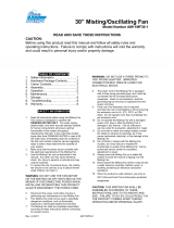
Handle the units with lifting straps.
If moving the units with a forklift truck or on rollers, ensure that the supporting
forks or rollers are positioned underneath the frame sections and not under
the oor plates.
When lifting the units with the aid of eye bolts (on request), use lifting ropes
that give you a minimum eye bolt distance L. Keep ropes at the same length.
Units with more than 4 eye bolts must be lifted with a lifting beam.
Please note
Handling
L
m
a
x.
6
0
°
min L

6 3040530_201503
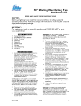
Insulation strips
on-site
KG 40-100:
Installation information
When being positioned on the base frame or foundation plinth, align the units
in such a way that a gap of approximately 10 mm is maintained between the
base frame or foundation plinth and the drip guard.
When installation is complete, securely x the air handling units to the base
frame or foundation plinth using the clips provided.
Washer
Screw
Clip
Stud
Drip guard
Base frame
LR
Base frames are delivered either securely tted to the unit or loose (in advance).
If the base frame is delivered in advance, replace the screw with the
stud provided.
Loose base frames are delivered in individual sections and must be assembled
on site in accordance with the instructions supplied with the base frame, levelled,
and secured to the plinth.
If units are delivered in sections with the base frame tted, the base frame and
unit will be split at the same points.
Unit connection The connection is made using M6 screws and spacer clips, for which holes
are provided at the appropriate points in the cubes. All small parts required
for assembly, plus loose accessories, are supplied in a unit with an inspection
door (preferably a fan section). This unit will be marked with a label reading
"Accessories inside unit".
In order to completely waterproof the unit, apply the self-adhesive sealing tape
supplied with the unit to one side before the cubes are joined.
For units with a scrubber, use a base frame or foundation plinth because the
scrubber base is lower than the remaining unit base. The required height of
this base frame depends on the type of scrubber and is determined individually
when designing the unit.
Foundation A level, horizontal and load-bearing surface is required to site and install the
units and unit components.
Base frames must be levelled horizontally; foundation plinths must also be
level and horizontal.
The entire lower unit frame must sit on the foundation; point loads are not
permissible.
To prevent structure-borne noise being transmitted from air handling units to
the building, insert a permanently exible intermediate layer between the plinth/
foundation and the unit/base frame. This intermediate layer should ideally take
the form of insulation strips, tted lengthwise below the unit frame sections.
Please note

3040530_201503 7
Installation information
KG 40-100
Only with recirculation air damper with
self-tapping hexagon screws Ø 8x25
Sealing tape
KG 15-100
Sealing tape
Unit arrangement:
stacked or adjacent
Stacked units are delivered separately and must be linked together on site
using the unit connectors and drilling screws provided.
Upper and lower or adjacent unit sections cannot be tted together until the
various transport units have been assembled at the nal installation site.
Stacked units
60
A
B
A
B
Length
Transport unit
Length
Transport unit
Stacked units
Mat. no. 6609800
Drilling screw
5.5 x 19
Mat. no. 3490234
Drilling screw
6.3 x 25
Mat. no. 3480038

8 3040530_201503
Installation information
The units are delivered fully assembled. To facilitate handling, they can be
taken apart and reassembled in the installation room.
With the version for disassembly, the frame sections split in the centre and are
secured with a at steel bar or angle bracket (secured with screws).
To split the KG 40-100, remove any frame insulation that is in place and ret
after the cubes have been assembled.
Versionfordisassembly
(on request)
KG 40-100
Canvasange/
louvre damper
Shipping
brackets
The fan shaft must always be horizontal.
With fans mounted on anti-vibration spring mounts, remove the transport brackets.
When installing, ensure that the distance between the connection anges is
not greater than 100 mm, to enable the canvas ange to move fully.
The canvas ange and louvre damper may need to be insulated on site against
both sound emission and the formation of condensate.
Please note
Fan section
Heat exchanger
Heat exchanger
Flange
Mist eliminator
Vorlauf
Vorlauf
Rücklauf
Rücklauf
Luftrichtung Luftrichtung
The heat exchangers (cooler, heater) operate using the countercurrent principle,
i.e. the heat transfer medium or refrigerant is channelled in the opposite direction
to the air ow. The relevant ow connection is therefore always located on the
air discharge side of the heat exchanger.
The heat exchangers must be connected in such a way that no mechanical
stress from the pipework is transferred to the heat exchangers.
Furthermore, the transmission of vibrations and thermal expansion between
the air handling unit and the pipework must be reliably prevented.
Ensure that the connection lines do not hinder access to other parts of the unit
(fan, lter, scrubber, etc.).
Regarding the heat exchanger (with ange), we recommend making the
connection with bends, so that the heat exchanger and mist eliminator can
later be extracted from the side for cleaning.
With steam coils, always arrange the steam intake at the top (large connection ø)
and the condensate drain at the bottom.
When connecting the ow and return lines, counterhold the threaded heat
exchanger connectors to prevent them from being twisted, otherwise the
application of mechanical force may detach the collector from the heat exchanger.
This would destroy the heat exchanger.
Ensure there are ventilation and drainage facilities on site.
Connect a siphon to the condensate drain connector on the cooler pan.
The connection pipes outside the external casing are insulated on site.
Please note
Please note
Flow
Flow
Return
Return
Air direction
Air direction

3040530_201503 9
Installation information
On-site cooler installation:
Direction of air ow
Condensate drain, siphon
Mist eliminator
Cooler
Remove casing and mist eliminator with condensate pan (mist eliminator is
placed in the guide rails for shipping).
Apply sealant to the mist eliminator frame and secure to the cooler bank.
The condensate drain apertures in the mist eliminator must be facing downwards.
Depending on the direction of the air ow, the removable cover panel must be
tted at the air intake on the collector side of the cooler bank.
Arrangement of mounting parts in the direction of the air ow:
Cooler bank, mist eliminator, condensate drain.
Insert the fully assembled unit into the cooler section; the cooler bank will be
held in place in the guide rails.
Fit casing.
Please note
When installing the scrubber, ensure that no dirt or other solid matter enters
the scrubber, as this would block the pump impeller and seriously impair or
completely destroy the pump.
If standard requirements apply, the water used for the scrubber must have at
least the following quality:
Appearance clear, colourless, no sediment
pH value 7 to 8.5
Total salt content < 800 g/m
3
Electrical conductivity < 100 mS/m (at 20 °C)
Calcium ion content > 0.5 mol/m
3
Carbonate hardness < 4.0 °d
Carbonate hardness
if using hardness stabilisers < 20 °d
Chloride content < 180 g/m
3
Sulphate content < 290 g/m
3
KMnO
4
consumption < 50 g/m
3
Bacteria count < 1000 ml
-1
If connecting the scrubber to the public water supply system, observe
DIN 1988 [or local standards].
Please note
Scrubber section

10 3040530_201503
Installation information
H
H
If the siphon is provided on site, establish the height of the siphon with reference
to the adjacent diagram.
The effective siphon height H (mm) must be greater than the maximum under-
or overpressure (in Pa) in the air handling unit (1 mmWC = 10 Pa).
The height differential between the unit discharge and the siphon overow
should also equal H (mm).
Double siphon
(on site)
Ball siphon
h
In order to drain away the condensate reliably, join a ball siphon to the condensate
drain connector onto the drain pan for the cooler/direct evaporator and onto
the KGX/KGXD plate heat exchanger pan.
Please note that a siphon must be tted to every condensate drain connector.
It is not permissible to join several drains to a common siphon.
The ball siphon is self-lling. A oat ball prevents air being drawn in when the
system is dry, so the initial condensate created can ll the siphon. The ball also
acts as a non-return valve and prevents the siphon from being completely drained.
In order to be able to t the siphon, ensure that the foundation is of the correct
height.
The effective siphon height h (mm) must be greater than the maximum under-
or overpressure at the condensate connector (1 mmWC = 10 Pa).
h = 1.5 x p (mmWC) + 50 mm (min.)
The siphon drain line must not be connected directly to the public sewage
system, but rather must be able to run out freely. Vent longer drain lines to
prevent condensate backing up in the line.
p Under- or overpressure in mmWC
according to appliance design
50 mm (WC) Reserve (imprecision in design, evaporation)
1.5 Additional safety factor

3040530_201503 11
Installation information /
Electrical connection
Intake/discharge hood Fit the side sections and top section as shown in the diagram using the screws
provided.
In the version with two intake/discharge hoods, one above the other, the upper
hood protrudes over the lower one.
Protrusion
Side sections
(drip moulding on outside)
Upper
section
Screws
Ensure that the appliance is isolated from the power supply.
Secure against reconnection.
Check that the connecting cables are tted correctly.
Always install an earth conductor.
Check the earth conductor.
Risk to life through electrocution.
Only use cables that meet the prescribed wiring regulations with regard to
voltage, current, insulation material, load, etc.
Ensure that there is sufcient protection against contact.
Before working on an electrical connection, the mains connections and PE
must be short circuited.
Check whether the data on the type plate corresponds to the connection data.
Before connecting the unit, ensure that the mains voltage corresponds to the
fan voltage.
Only use cables that are designed for the intensity of current according to the
type plate.
Electrical connection
Making the electrical connection

12 3040530_201503
Electrical connection
Electrical connection
Electrical connection should only be carried out by an electrician in accordance
with the applicable regulations (VDE, power supply utility, etc.).
Ifthesupplyorextractairfanisshutdownorfails,allcontrolvalvesmust
close automatically andthe hot/coldwater andscrubber pumpsmust
stop. Only use normally closed control valves and a frost stat without restart
lock. Otherwise, some components will continue to operate when the system
is shut down, which will prevent the safety equipment from working (e.g. frost
protection would not be guaranteed).
In order to safely shut down the air handling unit, install a lockable maintenance
isolator for every drive motor.
If, due to structural requirements, additional protective equipotential bonding is
required, this should be provided on site. The user or the certied electrician is
obliged to ensure correct earthing of the units in accordance with the applicable
national and local electrical and installation regulations.
Make the electrical connection in accordance with local regulations. After making
the electrical connection, a safety check of the installation must be carried out
in accordance with VDE 0701 Part 1 and VDE 0702. During commissioning, it
is important to ensure that the rotational direction of the fan is correct. Observe
the indicator arrow on the back panel of the unit.
Use only electric motors that are designed to drive fans.
Itisessentialthatyoutakenoteoftheconnectiondiagramintheterminal
box,becauseifconnectedincorrectly,themotormaynotbeabletoprovide
itsfulloutputormaybedestroyed.
For motors with PTC thermistors, use a PTC thermistor trigger device; for motors
with thermal contacts, use an interlock contactor; and for motors without PTC
thermistors or thermal contacts, use a thermal overload relay.
If connecting several KG : Connect the thermal contacts and frost stats in series.
Connect the KG motors and servomotors in parallel.
EC motors can be operated at variable speed across the entire range via a
0 – 10 V signal (DC). The motors are generally equipped with internally wired
temperature monitors.
Never route the unit's control cables immediately parallel to the power cable.
Ensure that there is as much clearance as possible.
Recommendation: Clearance > 10 cm (separate cable guide)
If the EC fan is only connected to the mains without connecting an additional
control unit to the fan's control connection, a jumper must be inserted between
the connections 0 – 10 V /PVM and +10 V. In this case, the fan runs at maximum
speed or air volume.
To restart the motor, switch off the mains voltage for at least 25 s and then
switch it back on.
Only AC/DC-sensitive fault current safety devices (type B) are permissible.
We recommend RCDs with a trip threshold of 300 mA.
Terminals and connections are live even when the unit has been switched off.
Do not touch the unit for 5 minutes after disconnecting the power across all
poles. If control voltage is present or a set speed is saved, the motor will restart
automatically, e.g. following a power failure.
Please note
Electricalconnection,ECfan
Please note
RCD
Motor fault

3040530_201503 13
Electrical connection
Single speed control
Motors up to 2.2 kW are usually started directly; from
3 kW they are started in star delta conguration.
L1
L1
U1
U1
W2
W2
W1
W1
V2
V2
V1
V1
U2
U2
L2
L2
L3
L3
W2 W2 W2U2 U2 U2
U1 U1
U1
L1 L1
L1
L2 L2
L2
L3 L3
L3
V1 V1
V1
W1 W1
W1
V2 V2 V2
Conguration of phase windings
Conguration on
terminal board
The ends of the
3 phase windings go
to the Y/∆ switch
Y/∆ switch
Y conguration∆ conguration
Dual speed control
(2 separate windings)
Version for e.g. 1000/1500 rpm or 750/1000 rpm
2U1
1U1
L1 L2 L3 N
2V1
1V1
2W1
1W1
L1
1U1
1W1
1V1
L2L3
L1
2U1
2W1
2V1
L2L3
0
1
2
1U1 2U1 1V1 2V1 1W12W1
L1
L2
L3
Low speed High speed
Contactor control
Pole changing switch
Dual speed control in a ratio of 1:2
(tapped winding conguration)
Version for e.g. 1500/3000 rpm or 750/1500 rpm
L1
1U
1U
2U
L1 L2 L3 N
1V
2V
1W
2W
2U
1W
2V
1V
2W
L2
L1
1U
2U
1W
2V
1V
2W
L2
L3
L3
0
1
2
1U 2U 1V 2V 1W 2W
L1
L2
L3
Use a winding conguration for an output gradation that is suitable for
a torque pattern for fan drive.
Low speed High speed
Contactor control Pole changing switch

14 3040530_201503
Commissioning
Fan section
Fixing screws
for V-belt pulleys
Adjustable pulley
Locking screw
ca. 15 mm
KG 40-100
V-belt
tensioning
screw
In accordance with DIN EN 1886, the unit must be opened with tools. Wait for
the fan to come to a complete standstill before opening the inspection doors.
When the doors are opened, negative pressure may draw in loose objects,
which could destroy the fan or even cause a risk to life if items of clothing are
drawn in.
Check that safety equipment such as V-belt or protective door grilles and
monitoring equipment is tted and functions correctly.
- Commissioning may only be carried out if the ducts are connected and the
inspection doors are closed. Otherwise there is a risk of motor overload.
- Check that the V-belt pulleys and locking screws in the clamping bushings
are rmly seated.
Adjustable V-belt pulleys are not set before the unit is delivered, so must be
adjusted accordingly on site when commissioning the air handling unit.
They allow the fan speed to be changed by 10 %.
Setting:
To alter the pulley diameter, the adjustable pulley can be moved axially on a
threaded shaft (see adjacent diagram).
To do this, the V-belt must be slack and the locking screws in the adjustable
pulley need to be undone using an Allen key. After adjusting the pulley, rmly
retighten the locking screws and adjust the V-belt tension correctly. When
tightening, both locking screws must rest on the attened threaded shaft.
- Check that the V-belt has the correct tension
(for retightening, see chapter on Maintenance).
The V-belt pulleys must be in perfect alignment.
- Turn ON the ON/OFF switch.
- Check the rotational direction of the fan impeller by briey switching on the
drive motor. Correct the rotational direction if required.
Proceed with the utmost caution as it is necessary to open the door to the
fan section for these steps. There is a risk that loose objects may be drawn
in, which could destroy the fan or even cause a risk to life if items of clothing
(ties) are drawn in.
- Check the air volume. Check the pressure drop.
- Check the power consumption of the fan motor:
Themotorcurrentandmotorratingmustnotexceedthevaluesspecied
onthemotortypeplate.Itisimperative that the maximumspecied
fan speed is not exceeded as otherwise the motor and fan would be
destroyedbythisoverloadandundoneoryingpartscoulddestroy
other components.
Regarding air handling units with a controllable motor and/or variable recirculating
air section, the maximum power consumption in the entire control range must
be checked.
If necessary, correct the air volume by replacing the pulleys (with adjustable
pulleys, alter the pulley(s); see above).
Please note
Please note
Please note

3040530_201503 15
Commissioning
Filter monitor
Airowmonitor
Frost stat
Heater
(warm water/hot water/steam)
Before commissioning, check the entire pipework system for leaks.
- Vent the heat exchanger and pipework system.
- With steam coils, secure the condensate drain to prevent damage to the
coil from steam hammers.
- Only start the heating water pump or open the water/steam valve when the
fan is running, to prevent overheating caused by insufcient heat transfer.
- Check the discharge temperature: Maximum discharge temperature 40 °C
if the heater is located on the intake side, otherwise there is a risk that the
motor will overheat.
- Protect heat exchangers against frost.
Be careful of hot surfaces of heat exchangers and connectors.
Risk of burns.
Louvre damper
(accessory)
The louvre dampers may need to be insulated on site against both sound
emission and the formation of condensate.
In the case of louvre dampers, follow the separately supplied installation
instructions for the damper servomotor.
Louvre damper drive shaft: 15 x 15 mm
Iflouvredampersarelocatedonthepressureside,openthemfully
before commissioning the fan.
Starting up the fan against closed louvre dampers can cause damage to the
unit.

16 3040530_201503
Commissioning
Electric heater
To prevent overheating, note the following minimum air volumes (in m³/h):
Unit type KG 15 20 25F 40F 40 63 100
Minimum air
volume (m
3
/h)
horizontal +
vertical ↑
550* 900 900 1600 1600 2500 acc. to unit
design
Minimum air
volume (m
3
/h)
vertical ↓
800* 1300 1300 2200 2200 3200 acc. to unit
design
*for 15 kW heating output
With multiple speed or variable speed motors, these air volumes must be
maintained at the lowest motor speed, irrespective of the heating output of the
electric heater.
Follow the relevant safety regulations for electric heaters.
It is essential to ensure that if the air ow fails, the electric heater will be
switched OFF automatically. Furthermore, the electric heater bank must only
be switched by one or more switching devices (contactors) the control current
of which is routed via the safety temperature limiter connected in series. Ensure
that at least one safety temperature limiter is located at the top on the inside
of the heater.
The electric heater bank must be protected from moisture and water.
Please note
Cooler
(cold water)
Before commissioning, check the entire pipework system for leaks.
- Vent the heat exchanger and pipework system.
- Secure the condensate drain to prevent the condensate pan overowing.
- If necessary, before commissioning a cold water cooler, check whether the
concentration of the antifreeze in the coolant is sufcient for the anticipated
temperature range. If antifreeze is added to the cold water, the output of the
cooler will be reduced in inverse proportion to the rising concentration of the
mixture.
- The discharge temperature must be above +2 °C (brine operation), otherwise
there is a risk of hoar frost and the downstream frost stat will issue a fault
message.
Antifreeze is harmful to health. It is essential to follow the manufacturer's safety
instructions when using antifreeze on site.

3040530_201503 17
Commissioning
Blow-downvalveassembly
(on request)
Adjust the blow-down volume at the manual valve.
(This blow-down volume depends on the water hardness and the dust content
in the air. As a rule of thumb, assume twice the evaporated water volume.)
Scrubber
- Check pipework and pump for leaks.
- Check that the nozzle holder and nozzles are rmly seated.
- Check that the siphon drain is unrestricted.
- Fill the siphon with water.
- Fill the scrubber pan until water drains from the siphon.
- To check the rotational direction, briey start the scrubber pump and
correct the rotational direction if required.
Check the power consumption of the pump motor.
Neverletthescrubberpumprundry.
Runningdrycandestroythepump.
- Start the supply air fan.
- Start the scrubber pump.
- Adjust the oat: Water level in the pan at least 10 mm above the pump
intake; maximum 10 mm below the overow outlet.
- If installed, adjust the run-dry protection and automatic desalination device
(as explained in separately supplied instructions).
Note: Mist eliminators allow moisture through for a limited time due to
their surface structure, resulting from their manufacturing process.
This is not a technical fault.
Please note
Cooler
(direct evaporator)
Before lling the refrigerant circuit with refrigerant, take suitable steps to ensure
that no residual moisture remains in the pipework system (e.g. evacuate or
purge with dry nitrogen).
Check the discharge temperature and evaporation temperature: minimum
temperature +2 °C. If the discharge temperature and refrigerant temperatures
are below +2 °C, there is a risk that the heat exchanger will freeze and the
downstream frost protection will respond.
The output for the direct evaporator can only be achieved if the refrigerant used
is the one on which the design is based (R134a).
Never allow refrigerant to escape into the environment as this creates a risk of
environmental pollution. Use a suitable suction device.
Please note

18 3040530_201503
Appliedtestforce(F)anddeectionvalues(x)forhighperformancenarrowV-beltsDIN7753
Belt prole Effective diameter
of the small pulley
(mm)
Force F
(N/belt)
SPZ 67 - 95
100 - 140
150 - 200
10 - 19
15 - 20
19 - 27
SPA 100 - 132
140 - 200
224 - 315
20 - 27
28 - 35
35 - 50
SPB 180 - 224
236 - 315
315 - 400
400 - 500
40 - 52
46 - 60
55 - 76
67 - 90
Deection x (mm)
Axle centre A (mm)
Maintenance
Before starting any maintenance work, turn the system ON/OFF switch OFF
and secure against reconnection. If it is switched ON again unintentionally,
people who enter the unit are at risk from rotating parts.
Wait for the fan to come to a complete standstill before opening the inspection
doors. When the doors are opened, negative pressure may draw in loose
objects, which could destroy the fan or even cause a risk to life if items of
clothing (ties) are drawn in.
Fan section
ca. 15 mm
V-belt
tensioning
screw
Initially recharge fan bearings with grease nipples with lithium soap grease after
approximately 50 hours run, and then every 2500 hours run.
Maintenance-free bearings are permanently lubricated and are identied
accordingly with labels.
Standard three-phase motors are maintenance-free.
In the case of special motors, follow the maintenance instructions of the motor
manufacturer.
Initially adjust the tension of V-belts after one hour in use. After this, checks at
regular intervals are required depending on the operating conditions, but should
be carried out at least every 4 months.
When changing the V-belt in multi groove drives, replace the entire belt set.
In the KG 40-100 Standard, the drive motor is attached to a sloping frame.
To adjust the tension of the V-belt, undo the locknut on the tensioning screw,
tighten the tensioning nut to the correct belt tension, and retighten the locknut.
Correct V-belt tension:
After tightening, the V-belt at the halfway point between the motor and fan shaft
must be able to be deected by about 15 mm.
Check that the V-belt pulleys are aligned.
Please note
approx. 15 mm

3040530_201503 19
Free-running impeller Motor and bearings are maintenance-free.
If necessary, clean the impeller with a soapy solution.
Impeller Motor
Flat belt drive
Check marks
Check that the fan drive shaft is exactly parallel to the motor drive shaft.
Check that the pulleys are in perfect alignment.
Thoroughly clean all pulley running surfaces of dirt, oil and grease.
Before the test run, turn the pulleys by hand to check the belt is running correctly.
After a 30 - 60 minute test run, check the belt drive and increase the pre-tension
if required (max. 2 %).
If using anged or edged pulleys, ensure that the belt does not come into
constant contact with the ange or edge, as this could destroy the belt.
Please note
Examples - test mark distances:
Slack 250 mm 350 mm 500 mm
Tensioned as per imprint on belt
Heat exchanger
(heater/cooler)
Louvre dampers
Check for contamination and clean at regular intervals.
Clean the heat exchanger by on of the following means:
- vacuuming
- blasting with compressed air
- spraying with water or steam.
Air/water/steam pressure for cleaning not above 5 bar, otherwise there is a
risk of the mechanically destruction of the components.
Check the condensate drain.
Open, clean and rell the siphon.
Clean the mist eliminator sections with commercially available descaling
agent.
Please note
Maintenance
Never lubricate the louvre dampers. This could destroy the plastic used and
compromise the function of the damper.
Blow compressed air through dampers; no other maintenance required.

20 3040530_201503
Maintenance / Frost protection
Heat exchanger
Warm/hot water heater, cold water cooler:
- Only site the KG air handling units in a room that is free from the risk of frost.
- Operation with commercially available antifreeze and frost stat.
- With the heating system switched OFF, drain all parts lled with water and
blow out remaining water using compressed air.
Steam coil:
- With the heating system switched OFF, drain all parts lled with water and
blow out remaining water using compressed air.
Electric heater:
- No frost protection measures required.
Scrubber
Insulate the water supply line on site; use a ribbon heater if required.
Drain pan and pipework; blow compressed air through pipework.
Drain pump (see separately supplied instructions from pump manufacturer).
Siphon
Protect siphon on site against freezing.
Frost protection measures
Clean scrubbers and mist eliminators at regular intervals. The cleaning cycles
depend on the operating mode, air condition and water quality.
For maintenance, drain the pan and rinse with clean water or a high pressure
cleaner.
Spray the pipework and nozzle holder only with reduced water pressure.
If the water pressure is too high, there is a risk of destroying components.
Commercially available descaling agents can be used.
Foaming cleaning agents are not suitable.
The scrubber pump is maintenance-free.
However, when cleaning the scrubber, we recommend ushing the pump and
pipework with clean water.
If the scrubber is idle for a prolonged period, run the pump once a week for
approximately 5 minutes to prevent the bearings seizing up (never run dry).
Please note
Please note
Scrubber
Filters
Fixing clips
To clean or replace the lter cartridges, open the inspection door and remove
the cartridges from the side of the unit casing.
The grade G4 synthetic bre lter mats used for the lter cartridges are
renewable. You can beat them, blow air through them, vacuum them or
wash them in lukewarm water with commercially available mild detergent.
Never wring out the mats.
Bag lters are not renewable; they have to be replaced due to contamination
when they exceed the permissible pressure drop.
To replace lter cartridges that are held in the unit frame with clips, open the
inspection door, release the clips and remove the cartridges from the side of
the unit casing towards the dusty side.
Replace lter bags once the recommended nal pressure drop has been reached.
/