Page is loading ...

738ZplusINT Z-WAVE INTERFACE
MODULE
Installation Guide
DESCRIPTION
1SELECT THE LOCATION
Select a central location for the 738ZplusINT Z-Wave Interface
Module. Keep in mind that at least one Z-Wave Plus device must
be within 65 feet of the module. Most Z-Wave Plus devices act as
repeaters for the signal to create longer and multiple transmission
routes (battery-powered Z-Wave Plus devices do not repeat signals
in order to extend battery life). See Figure 2.
Note: Place the module away from large, metal objects to
avoid interference with the Z-Wave Plus signal.
2MOUNT THE 738ZplusINT
1. With the housing cover o, carefully remove the
738ZplusINT’s PCB from the housing.
2. Use the supplied screws to secure the 738ZplusINT housing
against a wall or flat surface. See Figure 3.
The 738ZplusINT Z-Wave Interface
Module allows DMP panels to
communicate with up to 140
Z-Wave or Z-Wave Plus devices,
such as light controls, light bulbs,
door locks, garage door openers,
and thermostats.
The 738ZplusINT is automatically
recognized by DMP panels, and no
additional programming is required.
Once the module is connected to a
DMP panel, users can immediately
begin adding Z-Wave devices to
their system.
Devices can be remotely controlled
from smart phones using the DMP
Virtual Keypad™ App.
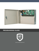
Figure 2: Example Z-Wave Plus Transmission Routes
= Z-Wave Plus Device
Oce Dining
Living Room
Foyer
Kitchen
Garage
Control
Panel with
738ZplusINT
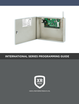
Figure 3: 738ZplusINT Housing with Mounting Holes
Mounting Holes
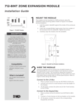
Figure 1: 738ZplusINT Z-Wave
Interface Module
Compatibility
• DMP XT30INT/XT50INT
Series panels
• DMP XR150INT/XR550INT
Series panels
• All Z-Wave and Z-Wave
Plus devices
• See the Compatibility section for
complete information.
What is Included?
• 738ZplusINT Z-Wave
Interface Module
• Hardware pack

2 738Zplus INSTALLATION GUIDE | DIGITAL MONITORING PRODUCTS
4ADD DEVICES
After wiring the 738ZplusINT to the panel, use a DMP keypad to program Z-Wave Plus devices into the
panel through the User Menu Z-Wave Setup option. This allows users to add devices through the User Menu
or the Virtual Keypad™ app after installation. When possible, have the Z-Wave device near the module
during setup and programming.
When programming Z-Wave devices into an XT30INT or XT50INT panel with Version 171 or higher, you can
add multiple devices at once. If you add multiple devices at once, then you will name each device after they
have all been added.
Note: To add the 738ZplusINT to an existing network, use the LRN (Learn) function.
1. Press CMD until MENU? YES NO appears, then press YES.
2. Press CMD until ZWAVE SETUP? appears. Press any select key or area.
3. Select ADD. The screen displays PROCESSING.
4. When prompted, press the button (or series of buttons if adding a thermostat) on the device you
are adding.
5. The keypad displays that the device has connected to your system.
3WIRE THE 738ZplusINT
The 738ZplusINT has four wire connections to connect to
the panel’s keypad bus. See Figure 4.
1. Connecting the wires to the 738ZplusINT terminals.
a. Connect the wire that delivers power to the
module to the RED terminal.
b. Connect the wire that sends data from the
module to the YEL terminal.
c. Connect the wire that receives data from
the panel to the GRN terminal.
d. Connect the ground wire to the BLK
terminal.
2. Carefully place the 738ZplusINT PCB back into
the housing, and then snap the housing cover
into place.
3. At the panel, connect the wires to the keypad bus
corresponding terminals.
Figure 4: 738ZplusINT Module
Wiring Connections
To Keypad Bus
REMOVE OR REPLACE DEVICES
If a device fails, users can remove or replace the device through the User Menu.
1. Press CMD until MENU? YES NO appears, then press YES.
2. Press CMD until ZWAVE SETUP? appears. Press any select key or area.
3. Select LIST and press CMD until the device you are removing or replacing displays. Then, press any
select key or area to select the device.
4. Select STATUS. The status of the device displays as either OKAY or FAILED. If the device fails,
REMOVE FAILED DEVICE displays.
5. Select YES to remove the device. Press the second select key or area to replace the device.
6. If you chose to replace the device, PROCESSING displays.
7. When prompted, press the button (or series of buttons if adding a thermostat) on the replacement
device.
8. The keypad displays that the device has connected to your system.
Note: The replacement device keeps the original device’s name.
5

738Zplus INSTALLATION GUIDE | DIGITAL MONITORING PRODUCTS 3
ADDITIONAL INFORMATION
LED Operation
The 738ZplusINT has three LEDs on the PCB that allow you to determine what type of operation is occurring. See Figure
4 for LED locations.
• PTX Green LED - If the light is blinking, then data is being sent to the panel.
• ZTX Green LED - If the light is blinking, then data is being sent to Z-Wave Plus devices.
• ZRX Yellow LED - If the light is blinking, then data is being received from Z-Wave Plus devices.
Z-Wave Terminology
Primary Controller: This is the main device used to set up and control your Z-Wave network. There can only be one
primary controller and it can be used to add or delete devices. A primary controller can be a portable device like a
hand-held remote, a static controller (permanently installed & never moved), a Z-Wave enabled PC or a Z-Wave enabled
Ethernet router/bridge.
Secondary Controller: The Z-Wave network supports multiple controllers so that additional Z-Wave remote controllers
can be used throughout the home. If the secondary controller is the same brand and model as the primary, it will have all
the same capabilities as the primary.
Home Control Network: The controllers and every Z-Wave device added with the primary controller are linked together
into a wireless network. Each device in the network has a unique address assigned to it and cannot be activated by a
neighbor’s Z-Wave controller.
Light/Node/Device: Node is the technical term used to describe a Z-Wave device in a home control network.
Please note that the terms “Node,” “Device,” and “Light” all refer to an individual Z-Wave enabled device and are
interchangeable within the context of these instructions.
Z-Wave Certification
• The 738ZplusINT is a Z-Wave Security enabled device.
• The 738ZplusINT can be added to an existing network as a secondary controller using the Learn (LRN) process.
• The 738ZplusINT is compatible with Z-Wave devices from all manufacturers.
• The 738ZplusINT can perform a Factory Default Reset by initializing defaults in the panel programming menu.
• The 738ZplusINT only supports group one with a maximum of one node.
• The 738ZplusINT takes no action when a basic set command is received.
Initialize Defaults
Only use this procedure when the Z-Wave network primary controller is missing or otherwise inoperable. Follow these
steps to initialize Z-Wave programming:
1. Reset the panel.
2. Enter 2313 (DIAG) at a keypad and press CMD to access the panel DIAGNOSTIC MENU.
3. Press CMD until INIT Z-WAVE displays and press a top row select key or area.
4. Select YES when Z-WAVE? NO YES displays. INIT SUCCESSFUL displays when all Z-Wave programming has been
initialized.
COMPATIBILITY
XT30INT/XT50INT Series Panels
738ZplusINT modules connected to DMP XT30/XT50 Series panels with Version 171 firmware or higher provide
full Z-Wave Plus functionality. DMP XT30/XT50 Series panels with Version 125 or earlier provide standard Z-Wave
functionality.
XR150INT/XR550INT Series Panels
738ZplusINT modules connected to DMP XR150/XR550 Series panels with Version 182 firmware or higher provide
full Z-Wave Plus functionality. DMP XR150/XR550 Series panels with Version 181 or earlier provide standard Z-Wave
functionality.
Note: If you are upgrading firmware for an XT30/XT50 Series or an XR150/XR550 Series panel that is already
connected to a 738ZplusINT, you will need to initialize panel defaults to access Z-Wave Plus functionality. See the
appropriate panel Programming Guide for more information on initializing defaults.

Designed, engineered, and
manufactured in Springfield, Missouri
using U.S. and global components.
INTRUSION • FIRE • ACCESS • NETWORKS
2500 North Partnership Boulevard
Springfield, Missouri 65803-8877
800.641.4282 | DMP.com
Specifications
Power Requirements
Operating Voltage 8 to 14 VDC
Current Draw 40 mA
Frequency Range 868 MHz
Dimensions 4.5”W x 2.75”H x 1.75”D
Color White
Housing Material Flame retardant ABS
Certifications
Industry Canada: 5251A-PC0137R2
CE: EN 300 220/489
738ZplusINT Z-WAVE
INTERFACE MODULE
© 2019 Digital Monitoring Products, Inc.
LT-1608INT 19345
/