Page is loading ...

User
Manual
SLC 500t
RTD/Resistance
Input Module
(Cat. No. 1746-NR4)
Allen-Bradley
AB Spares

Because of the variety of uses for the products described in this
publication, those responsible for the application and use of this
control equipment must satisfy themselves that all necessary steps
have been taken to assure that each application and use meets all
performance and safety requirements, including any applicable laws,
regulations, codes and standards.
The illustrations, charts, sample programs and layout examples
shown in this guide are intended solely for purposes of example.
Since there are many variables and requirements associated with any
particular installation, Allen-Bradley does not assume responsibility
or liability (to include intellectual property liability) for actual use
based upon the examples shown in this publication.
Allen-Bradley publication SGI-1.1, Safety Guidelines for the
Application, Installation, and Maintenance of Solid-State Control
(available from your local Allen-Bradley office), describes some
important differences between solid-state equipment and
electromechanical devices that should be taken into consideration
when applying products such as those described in this publication.
Reproduction of the contents of this copyrighted publication, in
whole or in part, without written permission of Allen-Bradley
Company, Inc., is prohibited.
Throughout this manual we use notes to make you aware of safety
considerations:
!
ATTENTION: Identifies information about practices
or circumstances that can lead to personal injury or
death, property damage or economic loss.
Attention statements help you to:
• identify a hazard
• avoid the hazard
• recognize the consequences
Important: Identifies information that is critical for successful
application and understanding of the product.
PLC, PLC-2, PLC-3, and PLC-5 are registered trademarks of Allen–Bradley Company, Inc.
SLC, SLC 500, MicroLogix, PanelView, RediPANEL, and Dataliner are trademarks of Allen–Bradley Company, Inc.
IBM is a registered trademark of International Business Machines, Incorporated.
Belden is a trademark of Belden, Inc.
Important User
Information

Summary of Changes
Summary of Changes
The information below summarizes the changes to this manual since the last
printing as 1746-6.7–January 1997.
To help you find new information and updated information in this release of
the manual, we have included change bars as shown to the right of this
paragraph.
The table below lists sections that document new features and additional
information about existing features, and shows where to find this new
information.
For This New Information See
Calibration page xiii
Single-point calibration page xiv
New Information
AB Spares

RTD/Resistance Input Module
User Manual
T
able of Contents
i
Preface
Who
Should Use this Manual
P–1. . . . . . . . . . . . . . . . . . . . . . . . . . . . . . . . . . .
Purpose
of this Manual
P–1. . . . . . . . . . . . . . . . . . . . . . . . . . . . . . . . . . . . . . . .
Contents
of this Manual
P–2. . . . . . . . . . . . . . . . . . . . . . . . . . . . . . . . . . . . .
Related
Documentation
P–3. . . . . . . . . . . . . . . . . . . . . . . . . . . . . . . . . . . . .
Terms
and Abbreviations
P–4. . . . . . . . . . . . . . . . . . . . . . . . . . . . . . . . . . . . . .
Common
Techniques Used in this Manual
P–6. . . . . . . . . . . . . . . . . . . . . . . . . .
Allen–Bradley
Support
P–6. . . . . . . . . . . . . . . . . . . . . . . . . . . . . . . . . . . . . . . .
Local
Product Support
P–6. . . . . . . . . . . . . . . . . . . . . . . . . . . . . . . . . . . . . .
Technical Product Assistance P–7. . . . . . . . . . . . . . . . . . . . . . . . . . . . . . . . .
Your Questions or Comments on this Manual P–7. . . . . . . . . . . . . . . . . . . . . .
Chapter 1
Description 1–1. . . . . . . . . . . . . . . . . . . . . . . . . . . . . . . . . . . . . . . . . . . . . . . .
RTD
Compatibility
1–3. . . . . . . . . . . . . . . . . . . . . . . . . . . . . . . . . . . . . . . . .
Resistance Device Compatibility 1–5. . . . . . . . . . . . . . . . . . . . . . . . . . . . . . .
Hardware Overview 1–5. . . . . . . . . . . . . . . . . . . . . . . . . . . . . . . . . . . . . . . .
General
Diagnostic Features
1–6. . . . . . . . . . . . . . . . . . . . . . . . . . . . . . . . .
System Overview 1–7. . . . . . . . . . . . . . . . . . . . . . . . . . . . . . . . . . . . . . . . . . .
System
Operation
1–8. . . . . . . . . . . . . . . . . . . . . . . . . . . . . . . . . . . . . . . . .
Powerup 1–8. . . . . . . . . . . . . . . . . . . . . . . . . . . . . . . . . . . . . . . . . . . . . .
Module
Operation
1–8. . . . . . . . . . . . . . . . . . . . . . . . . . . . . . . . . . . . . . .
LED
Status
1–9. . . . . . . . . . . . . . . . . . . . . . . . . . . . . . . . . . . . . . . . . . . .
Module to Processor Communication 1–10. . . . . . . . . . . . . . . . . . . . . . . . . . .
Chapter 2
Required
T
ools and Equipment
2–1. . . . . . . . . . . . . . . . . . . . . . . . . . . . . . . . . .
Procedures 2–2. . . . . . . . . . . . . . . . . . . . . . . . . . . . . . . . . . . . . . . . . . . . . . . .
Chapter 3
Compliance
to European Union Directives
3–1. . . . . . . . . . . . . . . . . . . . . . . . . .
EMC Directive 3–1. . . . . . . . . . . . . . . . . . . . . . . . . . . . . . . . . . . . . . . . . . . .
Electrostatic Damage 3–2. . . . . . . . . . . . . . . . . . . . . . . . . . . . . . . . . . . . . . . . .
NR4 Power Requirements 3–2. . . . . . . . . . . . . . . . . . . . . . . . . . . . . . . . . . . . .
Module
Location in Chassis
3–3. . . . . . . . . . . . . . . . . . . . . . . . . . . . . . . . . . . .
Modular Chassis Considerations 3–3. . . . . . . . . . . . . . . . . . . . . . . . . . . . . . .
Fixed Expansion Chassis Considerations 3–3. . . . . . . . . . . . . . . . . . . . . . . . .
General
Considerations
3–3. . . . . . . . . . . . . . . . . . . . . . . . . . . . . . . . . . . . .
Module
Installation and Removal
3–4. . . . . . . . . . . . . . . . . . . . . . . . . . . . . . . . .
Removing
the T
erminal Block 3–4. . . . . . . . . . . . . . . . . . . . . . . . . . . . . . . . .
Installing
the Module
3–5. . . . . . . . . . . . . . . . . . . . . . . . . . . . . . . . . . . . . . .
Removing
the Module
3–5. . . . . . . . . . . . . . . . . . . . . . . . . . . . . . . . . . . . . .
Terminal
Wiring
3–6. . . . . . . . . . . . . . . . . . . . . . . . . . . . . . . . . . . . . . . . . . . . .
NR4
Wiring Considerations
3–6. . . . . . . . . . . . . . . . . . . . . . . . . . . . . . . . . . .
Overview
Quick Start Guide
Installation and Wiring

RTD/Resistance Input Module
User Manual
T
able of Contents
ii
Wiring Resistance Devices (Potentiometers) to the NR4 Module 3–9. . . . . . . .
Wiring
Input Devices to the NR4 Module
3–12. . . . . . . . . . . . . . . . . . . . . . . . .
Calibration 3–13. . . . . . . . . . . . . . . . . . . . . . . . . . . . . . . . . . . . . . . . . . . . . . . .
Factory
Calibration
3–13. . . . . . . . . . . . . . . . . . . . . . . . . . . . . . . . . . . . . . . . .
Autocalibration 3–13. . . . . . . . . . . . . . . . . . . . . . . . . . . . . . . . . . . . . . . . . . .
Single–Point
Calibration
3–14. . . . . . . . . . . . . . . . . . . . . . . . . . . . . . . . . . . . .
Chapter 4
Module
ID Code
4–1. . . . . . . . . . . . . . . . . . . . . . . . . . . . . . . . . . . . . . . . . . . .
Module
Addressing
4–2. . . . . . . . . . . . . . . . . . . . . . . . . . . . . . . . . . . . . . . . . .
Output
Image – Configuration W
ords 4–2. . . . . . . . . . . . . . . . . . . . . . . . . . . .
Input
Image – Data W
ords and Status W
ords 4–3. . . . . . . . . . . . . . . . . . . . . .
Channel
Filter Frequency Selection
4–3. . . . . . . . . . . . . . . . . . . . . . . . . . . . . . .
Channel
Step Response
4–4. . . . . . . . . . . . . . . . . . . . . . . . . . . . . . . . . . . . .
Effective
Resolution
4–5. . . . . . . . . . . . . . . . . . . . . . . . . . . . . . . . . . . . . . . .
Channel Cut–Of
f Frequency
4–5. . . . . . . . . . . . . . . . . . . . . . . . . . . . . . . . . .
Scanning
Process and Channel T
iming 4–9. . . . . . . . . . . . . . . . . . . . . . . . . . . .
Channel
Autocalibration
4–9. . . . . . . . . . . . . . . . . . . . . . . . . . . . . . . . . . . . .
Update
T
ime and Scanning Process 4–9. . . . . . . . . . . . . . . . . . . . . . . . . . . .
Channel
T
urn–On, T
urn–Of
f, and Reconfiguration T
imes 4–11. . . . . . . . . . . . . . . .
Response
to Slot Disabling
4–11. . . . . . . . . . . . . . . . . . . . . . . . . . . . . . . . . . . . .
Input Response 4–11. . . . . . . . . . . . . . . . . . . . . . . . . . . . . . . . . . . . . . . . . . .
Output Response 4–11. . . . . . . . . . . . . . . . . . . . . . . . . . . . . . . . . . . . . . . . . .
Chapter 5
Channel
Configuration
5–1. . . . . . . . . . . . . . . . . . . . . . . . . . . . . . . . . . . . . . . .
Channel
Configuration Procedure
5–2. . . . . . . . . . . . . . . . . . . . . . . . . . . . . . . .
Configure
Each Channel
5–2. . . . . . . . . . . . . . . . . . . . . . . . . . . . . . . . . . . .
Enter
the Configuration Data
5–3. . . . . . . . . . . . . . . . . . . . . . . . . . . . . . . . . .
Input
Type Selection (Bits 0–3)
5–5. . . . . . . . . . . . . . . . . . . . . . . . . . . . . . . .
Data
Format Selection (Bits 4 and 5)
5–5. . . . . . . . . . . . . . . . . . . . . . . . . . . .
Using
Scaled–For–PID and Proportional Counts Formats
5–5. . . . . . . . . . .
Scaling Examples 5–8. . . . . . . . . . . . . . . . . . . . . . . . . . . . . . . . . . . . . . .
Scaled–for–PID
to Engineering Units
5–8. . . . . . . . . . . . . . . . . . . . . . . . . .
Engineering
Units to Scaled–for–PID
5–8. . . . . . . . . . . . . . . . . . . . . . . . . .
Proportional
Counts to Engineering Units
5–8. . . . . . . . . . . . . . . . . . . . . . .
Engineering
Units to Proportional Counts
5–8. . . . . . . . . . . . . . . . . . . . . . .
Broken
Input Selection (Bits 6 and 7)
5–12. . . . . . . . . . . . . . . . . . . . . . . . . . . .
Temperature
Units Selection (Bit 8)
5–12. . . . . . . . . . . . . . . . . . . . . . . . . . . . .
Filter
Frequency Selection (Bits 9 and 10)
5–13. . . . . . . . . . . . . . . . . . . . . . . .
Channel
Enable Selection (Bit 1
1) 5–13. . . . . . . . . . . . . . . . . . . . . . . . . . . . . .
Excitation
Current Selection (Bit 12)
5–14. . . . . . . . . . . . . . . . . . . . . . . . . . . .
Scaling
Select (Bits 13–14)
5–14. . . . . . . . . . . . . . . . . . . . . . . . . . . . . . . . . . .
Default
Scaling –
5–15. . . . . . . . . . . . . . . . . . . . . . . . . . . . . . . . . . . . . . . .
Preliminary Operating
Considerations
Channel Configuration,
Data, and Status
AB Spares

RTD/Resistance Input Module
User Manual
T
able of Contents
iii
User–set
Scaling –
5–15. . . . . . . . . . . . . . . . . . . . . . . . . . . . . . . . . . . . . . .
Configuration Words For User–set Scaling (W
ords 4 to 7)
5–16. . . . . . . . . . .
Unused
(Bit 15)
5–17. . . . . . . . . . . . . . . . . . . . . . . . . . . . . . . . . . . . . . . . . . .
Channel
Data W
ord 5–18. . . . . . . . . . . . . . . . . . . . . . . . . . . . . . . . . . . . . . . . . .
Channel Status Checking 5–19. . . . . . . . . . . . . . . . . . . . . . . . . . . . . . . . . . . . . .
Input
T
ype Status (Bits 0–3)
5–21. . . . . . . . . . . . . . . . . . . . . . . . . . . . . . . . . .
Data
Format Status (Bits 4 and 5)
5–21. . . . . . . . . . . . . . . . . . . . . . . . . . . . . .
Broken
Input Status (Bits 6 and 7)
5–21. . . . . . . . . . . . . . . . . . . . . . . . . . . . . .
Temperature
Units Status (Bit 8)
5–21. . . . . . . . . . . . . . . . . . . . . . . . . . . . . . .
Channel
Filter Frequency (Bits 9 and 10)
5–21. . . . . . . . . . . . . . . . . . . . . . . . .
Channel
Enable Status (Bit 1
1) 5–22. . . . . . . . . . . . . . . . . . . . . . . . . . . . . . . .
Excitation
Current (Bit 12)
5–22. . . . . . . . . . . . . . . . . . . . . . . . . . . . . . . . . . . .
Broken
Input Error (Bit 13)
5–22. . . . . . . . . . . . . . . . . . . . . . . . . . . . . . . . . . .
Out–Of–Range
Error (Bit 14)
5–23. . . . . . . . . . . . . . . . . . . . . . . . . . . . . . . . .
Configuration
Error (Bit 15)
5–23. . . . . . . . . . . . . . . . . . . . . . . . . . . . . . . . . . .
Chapter 6
Device
Configuration
6–1. . . . . . . . . . . . . . . . . . . . . . . . . . . . . . . . . . . . . . . . .
Initial Programming 6–2. . . . . . . . . . . . . . . . . . . . . . . . . . . . . . . . . . . . . . . . . .
Procedure 6–3. . . . . . . . . . . . . . . . . . . . . . . . . . . . . . . . . . . . . . . . . . . . . . .
Dynamic Programming 6–4. . . . . . . . . . . . . . . . . . . . . . . . . . . . . . . . . . . . . . . .
Procedure 6–4. . . . . . . . . . . . . . . . . . . . . . . . . . . . . . . . . . . . . . . . . . . . . . .
Verifying
Channel Configuration Changes
6–5. . . . . . . . . . . . . . . . . . . . . . . . . .
Interfacing
to the PID Instruction
6–7. . . . . . . . . . . . . . . . . . . . . . . . . . . . . . . . .
Using
the Proportional Counts Data Format with the User–set Scaling
6–9. . . . . .
Monitoring
Channel Status Bits
6–10. . . . . . . . . . . . . . . . . . . . . . . . . . . . . . . . . .
Invoking
Autocalibration
6–11. . . . . . . . . . . . . . . . . . . . . . . . . . . . . . . . . . . . . . .
Chapter 7
Module
Operation vs. Channel Operation
7–1. . . . . . . . . . . . . . . . . . . . . . . . . . .
Power–Up Diagnostics 7–1. . . . . . . . . . . . . . . . . . . . . . . . . . . . . . . . . . . . . . . .
Channel Diagnostics 7–1. . . . . . . . . . . . . . . . . . . . . . . . . . . . . . . . . . . . . . . . .
LED
Indicators
7–2. . . . . . . . . . . . . . . . . . . . . . . . . . . . . . . . . . . . . . . . . . . . . .
Error Codes 7–3. . . . . . . . . . . . . . . . . . . . . . . . . . . . . . . . . . . . . . . . . . . . . . .
Channel Status LEDs (Green) 7–4. . . . . . . . . . . . . . . . . . . . . . . . . . . . . . . . .
Invalid
Channel Configuration
7–4. . . . . . . . . . . . . . . . . . . . . . . . . . . . . . .
Open–
and Short–Circuit Detection
7–4. . . . . . . . . . . . . . . . . . . . . . . . . . .
Out–Of–Range
Detection
7–5. . . . . . . . . . . . . . . . . . . . . . . . . . . . . . . . . .
Module Status LED (Green) 7–5. . . . . . . . . . . . . . . . . . . . . . . . . . . . . . . . . .
Replacement Parts 7–7. . . . . . . . . . . . . . . . . . . . . . . . . . . . . . . . . . . . . . . . . .
Contacting
Allen–Bradley
7–7. . . . . . . . . . . . . . . . . . . . . . . . . . . . . . . . . . . . . .
Chapter 8
Basic Example 8–1. . . . . . . . . . . . . . . . . . . . . . . . . . . . . . . . . . . . . . . . . . . . .
Ladder Programming
Examples
Module Diagnostics and
Troubleshooting
Application Examples

RTD/Resistance Input Module
User Manual
T
able of Contents
iv
Channel
Configuration
8–1. . . . . . . . . . . . . . . . . . . . . . . . . . . . . . . . . . . . . .
Program
Listing
8–3. . . . . . . . . . . . . . . . . . . . . . . . . . . . . . . . . . . . . . . . . . .
Data
T
able 8–3. . . . . . . . . . . . . . . . . . . . . . . . . . . . . . . . . . . . . . . . . . . . . .
Supplementary Example 8–4. . . . . . . . . . . . . . . . . . . . . . . . . . . . . . . . . . . . . .
Channel
Configuration
8–5. . . . . . . . . . . . . . . . . . . . . . . . . . . . . . . . . . . . . .
Program
Setup and Operation Summary
8–7. . . . . . . . . . . . . . . . . . . . . . . . .
Program
Listing
8–8. . . . . . . . . . . . . . . . . . . . . . . . . . . . . . . . . . . . . . . . . . .
Data
T
able 8–9. . . . . . . . . . . . . . . . . . . . . . . . . . . . . . . . . . . . . . . . . . . . . .
Appendix A
Electrical
Specifications
A–1. . . . . . . . . . . . . . . . . . . . . . . . . . . . . . . . . . . . . . .
Physical
Specifications
A–1. . . . . . . . . . . . . . . . . . . . . . . . . . . . . . . . . . . . . . . .
Module
Environmental Specifications
A–2. . . . . . . . . . . . . . . . . . . . . . . . . . . . .
Input
Specifications
A–2. . . . . . . . . . . . . . . . . . . . . . . . . . . . . . . . . . . . . . . . . .
Module Accuracy A–3. . . . . . . . . . . . . . . . . . . . . . . . . . . . . . . . . . . . . . . . . .
Resistance Device Compatibility A–5. . . . . . . . . . . . . . . . . . . . . . . . . . . . . . .
Cable
Specifications
A–5. . . . . . . . . . . . . . . . . . . . . . . . . . . . . . . . . . . . . . .
Appendix B
Appendix C
Channel
Configuration Procedure
C–1. . . . . . . . . . . . . . . . . . . . . . . . . . . . . . . .
Specifications
RTD Standards
Configuration Worksheet
for RTD/Resistance Module
AB Spares

Preface
P–1
Preface
Read this preface to familiarize yourself with the rest of the manual. This
preface covers the following topics:
• who should use this manual
• the purpose of this manual
• terms and abbreviations
• conventions used in this manual
• Allen–Bradley support
Use this manual if you are responsible for designing, installing,
programming, or troubleshooting control systems that use Allen–Bradley
small logic controllers.
You should have a basic understanding of SLC 500t products. You should
understand programmable controllers and be able to interpret the ladder logic
instructions required to control your application. If you do not, contact your
local Allen–Bradley representative for information on available training
courses before using this product. If using Advanced Programming Software
(APS), we recommend that you review The APS Quick Start for New Users,
Publication 9399-APSQS.
This manual is a reference guide for the 1746–NR4 RTD/Resistance Input
Module. The manual:
• gives you an overview of system operation
• explains the procedures you need to install and wire the module at the
customer site
• provides ladder programming examples
• provides an application example of how this input module can be used to
control a process
Who Should Use this
Manual
Purpose of this Manual

Preface
P–2
Contents of this Manual
Chapter Title Contents
Preface
Describes the purpose, background, and scope of
this manual. Also specifies the audience for whom
this manual is intended and defines key terms and
abbreviations used throughout this book.
1 Overview
Provides a hardware and system overview.
Explains and illustrates the theory behind the RTD
input module.
2 Quick Start Guide
Provides a general procedural roadmap to help you
get started using the RTD module.
3 Installation and Wiring
Provides installation procedures and wiring
guidelines.
4
Preliminary Operating
Considerations
Gives you the background information you need to
understand how to address and configure the
module for optimum operation as well as how to
make changes once the module is in a run state.
5
Channel Configuration,
Data, and Status
Examines the channel configuration word and the
channel status word bit by bit, and explains how the
module uses configuration data and generates
status during operation.
6 Ladder Programming Examples
Gives an example of the ladder logic required to
define the channel for operation. Also includes
representative examples for unique programming
requirements such as PID.
7
Module Diagnostics and
Troubleshooting
Explains how to interpret and correct problems with
your RTD module.
8 Application Examples
Examines both basic and supplementary
applications and gives examples of the ladder
programming necessary to achieve the desired
result.
Appendix A Specifications
Provides physical, electrical, environmental, and
functional specifications for the RTD module.
Appendix B RTD Standards
Provides physical, electrical, environmental, and
functional specifications for the RTD and
potentiometer.
Appendix C
Configuration Worksheet
for RTD/Resistance Module
Provides a worksheet to help you configure the
module for operation.
AB Spares

Preface
Preface
P–3
Related Documentation
The following documents contain information that may be helpful to you as
you use Allen–Bradley SLCt products. To obtain a copy of any of the
Allen–Bradley documents listed, contact your local Allen–Bradley office or
distributor.
For Read this Document
Document
Number
An overview of the SLC 500 family of products SLC 500 System Overview 1747–2.30
A description on how to install and use your Modular SLC 500
programmable controller
Installation & Operation Manual for Modular Hardware
Style Programmable Controllers
1747–6.2
A description on how to install and use your Fixed SLC 500
programmable controller
Installation & Operation Manual for Fixed Hardware Style
Programmable Controllers
1747–6.21
A procedural manual for technical personnel who use APS to develop
control applications
Rockwell Software Advanced Programming Software
(APS) User Manual
9399-APSUM
A reference manual that contains status file data, instruction set, and
troubleshooting information about APS
SLC 500t and MicroLogix 1000t Instruction Set
Reference Manual
1747–6.15
An introduction to APS for first–time users, containing basic concepts but
focusing on simple tasks and exercises, and allowing the reader to begin
programming in the shortest time possible
APS Quick Start for New Users 9399-APSQS
A procedural and reference manual for technical personnel who use an
HHT to develop control applications
Allen-Bradley Hand-Held Terminal User’s Manual 1747–NP002
An introduction to HHT for first–time users, containing basic concepts but
focusing on simple tasks and exercises, and allowing the reader to begin
programming in the shortest time possible
Getting Started Guide for HHT 1747–NM009
A resource manual and user’s guide containing information about the
analog modules used in your SLC 500 system.
SLC 500 Analog I/O Modules User’s Manual 1746–6.4
In–depth information on grounding and wiring Allen–Bradley
programmable controllers
Allen-Bradley Programmable Controller Grounding and
Wiring Guidelines
1770–4.1
A description of important differences between solid–state programmable
controller products and hard–wired electromechanical devices
Application Considerations for Solid–State Controls SGI–1.1
A complete listing of current AllenBradley documentation, including
ordering instructions. Also indicates whether the documents are
available on CD–ROM or in multi–languages.
Allen-Bradley Publication Index SD499
A glossary of industrial automation terms and abbreviations Allen-Bradley Industrial Automation Glossary AG–7.1
An article on wire sizes and types for grounding electrical equipment National Electrical Code
Published by the
National Fire
Protection
Association of
Boston, MA.

Preface
P–4
The following terms and abbreviations are specific to this product. For a
complete listing of Allen–Bradley terminology, refer to the Allen–Bradley
Industrial Automation Glossary, Publication Number AG–7.1.
A/D – Refers to the analog–to–digital converter inherent to the
RTD/Resistance input module. The converter produces a digital value whose
magnitude is proportional to the instantaneous magnitude of an analog input
signal.
attenuation – The reduction in the magnitude of a signal as it passes through
a system.
channel – Refers to one of four small–signal analog input interfaces
available on the module’s terminal block. Each channel is configured for
connection to an RTD or potentiometer input device and has its own
diagnostic status word.
chassis – A hardware assembly that houses devices such as I/O modules,
adapter modules, processor modules, and power supplies.
common mode rejection ratio – The ratio of a device’s differential voltage
gain to common mode voltage gain, expressed in dB.
CMRR = 20 Log
10
(V1/V2)
common mode voltage – A voltage signal induced in conductors with
respect to ground (0 potential).
configuration word – Contains the channel configuration information
needed by the module to configure and operate each channel. Information is
written to the configuration word through the logic supplied in your ladder
program.
cut–off frequency – The frequency at which the input signal is attenuated
3dB by the digital filter. Frequency components of the input signal below the
cut–off frequency are passed with under 3dB of attenuation.
data word – A 16–bit integer that represents the value of the analog input
channel. The channel data word is valid only when the channel is enabled
and there are no channel errors. When the channel is disabled, the channel
data word is cleared (0).
dB (decibel) – A logarithmic measure of the ratio of two signal levels.
digital filter – A low–pass noise filter incorporated into the A/D converter.
In addition, the digital filter provides high–rejection notches at frequencies
that are integral multiples of the filter cut–off frequency. The notches are
used for rejecting AC power line noise and higher frequency noise.
excitation current – A user–selectable current (0.5 mA and 2.0 mA) that the
module sends through the RTD or resistive device to produce an analog
signal which the NR4 can process and convert to temperature or to ohms,
respectively.
Terms and Abbreviations
AB Spares

Preface
Preface
P–5
effective resolution – The amount of jitter (data variation) that typically
occurs in the data word due to the influence of the internal electrical noise in
the module.
filter frequency – The user–selectable first–notch frequency for the A/D
converter’s digital filter. The digital filter provides AC power line noise
rejection when the first notch is at 10 Hz or at the power line frequency.
full scale error (gain error) – The difference in slope between the actual and
ideal potentiometer or RTD transfer functions.
full scale range (FSR) – The difference between the maximum and
minimum specified analog RTD or resistive input values.
gain drift – The change in full scale transition voltage measured over the
operating temperature range of the module.
input data scaling –The data formats that you select to define the logical
increments of the channel data word. These may be scaled–for–PID, or
Engineering Units for RTD or potentiometer inputs, which are automatically
scaled. They may also be proportional counts, which you must calculate to
fit your application’s temperature or resistance resolution.
local configuration – A control system where all the chassis are located
within several feet of the processor and chassis–to–chassis communication is
via a 1746–C7 or 1746–C9 ribbon cable.
LSB (Least Significant Bit) – Refers to a data increment defined as the full
scale range divided by the resolution. The LSB represents the smallest value
within a string of bits.
multiplexer – A switching system that allows several input signals to share a
common A/D converter.
normal mode rejection (differential mode rejection) – A logarithmic
measure in dB, of a device’s ability to reject noise signals between or among
circuit signal conductors, but not between equipment grounding conductor or
signal reference structure and the signal conductors.
potentiometer (Pot) – A variable resistor that can be connected to the RTD
module.
remote configuration – A control system where the chassis can be located
several thousand feet from the processor chassis. Chassis communication is
via the 1747–SN Scanner and 1747–ASB Remote I/O Adapter.
resolution – The smallest detectable change in a measurement, typically
expressed in engineering units (e.g., 0.1 °C) or as a number of bits. For
example, a 12–bit system has 4,096 possible output states. It can, therefore,
measure 1 part in 4096.
RTD (Resistance Temperature Detector) – A temperature sensing element
with 2, 3 or 4 lead wires. It uses the basic characteristic that electrical

Preface
P–6
resistance of metals increases with temperature. When a small current is
applied to the RTD, it creates a voltage that varies with temperature. This
voltage is processed and converted by the RTD module into a temperature
value.
sampling time – The time required by the A/D converter to sample an input
channel.
status word – Contains status information about the channel’s current
configuration and operational state. You can use this information in your
ladder program to determine whether the channel data word is valid.
step response time – This is the time required for the A/D input signal to
reach 100% of its expected final value, given a large step change in the input
signal.
update time – The time required for the module to sample and convert the
input signals of all enabled input channels and make the resulting data values
available to the SLC processor.
The following conventions are used throughout this manual:
• Bulleted lists such as this one provide information, not procedural steps.
• Numbered lists provide sequential steps or hierarchical information.
• Italic type is used for emphasis.
• Text in this
font
indicates words or phrases you should type.
Allen–Bradley offers support services worldwide, with over 75 Sales/Support
Offices, 512 authorized Distributors and 260 authorized Systems Integrators
located throughout the United States alone, plus Allen–Bradley
representatives in every major country in the world.
Local Product Support
Contact your local Allen–Bradley representative for:
• sales and order support
• product technical training
• warranty support
• support service agreements
Technical Product Assistance
If you need to contact Allen–Bradley for technical assistance, please review
the information in the Module Diagnostics and Troubleshooting chapter first.
Then call your local Allen–Bradley representative.
Common Techniques Used in
this Manual
Allen–Bradley Support
AB Spares

Preface
Preface
P–7
Your Questions or Comments on this Manual
If you find a problem with this manual, please notify us of it on the enclosed
Publication Problem Report.
If you have any suggestions for how this manual could be made more useful
to you, please contact us at the address below:
Allen–Bradley Company, Inc.
Control and Information Group
Technical Communication, Dept. A602V, T122
P.O. Box 2086
Milwaukee, WI 53201–2086

Preface
P–8
Notes:
AB Spares

1
Chapter
1–1
Overview
This chapter describes the 4–channel 1746–NR4 RTD/Resistance Input
Module and explains how the SLC controller gathers RTD (Resistance
Temperature Detector) temperature or resistance–initiated analog input from
the module. Included is:
• general description of the module’s hardware and software features
• an overview of system operation
For the rest of the manual, the 1746–NR4 RTD/Resistance Input Module will
be referred to as simply the RTD module.
The RTD module receives and stores digitally converted analog data from
RTDs or other resistance inputs such as potentiometers into its image table
for retrieval by all fixed and modular SLC 500 processors. An RTD consists
of a temperature–sensing element connected by 2, 3, or 4 wires that provide
input to the RTD module. The module supports connections from any
combination of up to four RTDs of various types (for example: platinum,
nickel, copper, or nickel–iron) or other resistance inputs.
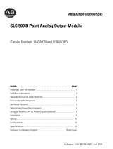
As shown in Figure 1.1, the RTD module supplies a small current to each
RTD connected to the module inputs (up to 4 input channels). The module
provides on–board scaling and converts RTD input to temperature (
°C,
°F
)
or
reports resistance input in ohms.
Each input channel is individually configurable for a specific input device.
Broken sensor detection (open– or short–circuit) is provided for each input
channel. In addition, the module provides indication if the input signal is
out–of–range. For more detail on module functionality refer to the
subsection entitled System Overview later in this chapter.
Description

Chapter 1
Overview
1–2
Figure 1.1
Simplified RTD Module Circuit
RTD
µP Circuit
RTD
0
Sense
Return
I
C=
0.5
or
2
mA
Constant Current Source
A/D
Conversion
Digital Data
Backplane
RTD
1
RTD
2
RTD Module
RTD
3
Digital Data
RTD
Sense
Return
RTD
Sense
Return
RTD
Sense
Return
AB Spares

Chapter 1
Overview
1–3
RTD Compatibility
Table 1.A lists the RTD types you can use with the RTD module and gives
each type’s associated temperature range, resolution, and repeatability
specifications. Table 1.B shows the accuracy and temperature drift
specifications for the RTDs.
Table 1.A
RTD Temperature Ranges, Resolution, and Repeatability
RTD Type
Temp. Range
(0.5 mA Excitation)➁
Temp. Range
(2.0 mA Excitation)➁
Resolution Repeatability
100Ω
–200 °C to +850 °C
(–328 °F to +1562 °F)
–200 °C to +850 °C
(–328 °F to +1562 °F)
0.1 °C
(0.2 °F)
0.2
°C
( 0.4
°F)
Platinum 385 ➀
200W
–200 °C to +850 °C
(–328 °F to +1562 °F)
–200 °C to +850 °C
(–328 °F to +1562 °F)
0.1 °C
(0.2 °F)
0.2
°C
( 0.4
°F)
Platinum
(
385
)➀
500W
–200 °C to +850 °C
(–328 °F to +1562 °F)
–200 °C to +850 °C
(–328 °F to +1562 °F)
0.1 °C
(0.2 °F)
0.2
°C
( 0.4
°F)
1000W
–200 °C to +850 °C
(–328 °F to +1562 °F)
–200 °C to +240 °C
(–328 °F to +464 °F)
0.1 °C
(0.2 °F)
0.2
°C
( 0.4
°F)
100W
–200 °C to +630 °C
(–328 °F to +1166°F)
–200 °C to +630 °C
(–328 °F to +1166 °F)
0.1 °C
(0.2 °F)
0.2
°C
( 0.4
°F)
Platinum 3916 ➀
200W
–200 °C to +630 °C
(–328 °F to +1166°F)
–200 °C to +630 °C
(–328 °F to +1166 °F)
0.1 °C
(0.2 °F)
0.2
°C
( 0.4
°F)
Platinum
(
3916
)➀
500W
–200 °C to +630 °C
(–328 °F to +1166°F)
–200 °C to +630 °C
(–328 °F to +1166 °F)
0.1 °C
(0.2 °F)
0.2
°C
( 0.4
°F)
1000W
–200 °C to +630 °C
(–328 °F to +1166°F)
–200 °C to +230 °C
(–328 °F to +446 °F)
0.1 °C
(0.2 °F)
0.2
°C
( 0.4
°F)
Copper (426)➀➂ 10W Not allowed.➄
–100 °C to +260 °C
(–148 °F to +500 °F)
0.1 °C
(0.2 °F)
0.2
°C
( 0.4
°F)
Nickel (618)➀➃ 120W
–100 °C to +260 °C
(–148 °F to +500 °F)
–100 °C to +260 °C
(–148 °F to +500 °F)
0.1 °C
(0.2 °F)
0.1
°C
( 0.2
°F)
Nickel (672)➀ 120W
–80 °C to +260 °C
(–112 °F to +500 °F)
–80 °C to +260 °C
(–112 °F to +500 °F)
0.1 °C
(0.2 °F)
0.1
°C
( 0.2
°F)
Nickel Iron (518)➀ 604W
–100 °C to +200 °C
(–148 °F to +392 °F)
–100 °C to +200 °C
(–148 °F to +392 °F)
0.1 °C
(0.2 °F)
0.1
°C
( 0.2
°F)
➀
The
digits following the R
TD type represent the temperature coef
ficient of resistance (
α
), which is defined as the resistance change
per ohm per
°
C. For instance, Platinum 385
refers to a platinum R
TD with
α
= 0.00385 ohms/ohm –
°
C or simply 0.00385 /
°C.
➁
The temperature range for the 1000
W
R
TD is dependant on the excitation current.
➂
Actual value at 0
°
C is 9.042
W
per
SAMA standard RC21–4–1966.
➃
Actual value at 0
°
C is 100
W
per
DIN standard.
➄ To maximize the relatively small R
TD signal, only 2 mA excitation current is allowed.
Important: The exact signal range valid for each input type is dependent
upon the excitation current magnitude that you select when
configuring the module. For details on excitation current, refer
to page ii.

Chapter 1
Overview
1–4
Table 1.B
RTD Accuracy and Temperature Drift Specifications
RTD Type
Accuracy➁
(0.5 mA Excitation)
Accuracy➁
(2.0 mA Excitation)
Temperature Drift➅
(0.5 mA Excitation)
Temperature Drift➅
(2.0 mA Excitation)
100W
1.0
°C
( 2.0
°F)
0.5
°C
( 0.9
°F)
0.034
°C/°C
( 0.061
°F/°F)
0.014
°C/°C
( 0.025
°F/°F)
Platinum 385 ➀
200W
1.0
°C
( 2.0
°F)
0.5
°C
( 0.9
°F)
0.034
°C/°C
( 0.061
°F/°F)
0.014
°C/°C
( 0.025
°F/°F)
Platinum
(
385
)➀
500W
0.6
°C
( 1.1
°F)
0.5
°C
( 0.9
°F)
0.017
°C/°C
( 0.031
°F/°F)
0.014
°C/°C
( 0.025
°F/°F)
1000W
0.6
°C
( 1.1
°F)
0.5
°C
( 0.9
°F)
0.017
°C/°C
( 0.031
°F/°F)
0.014
°C/°C
( 0.025
°F/°F)
100W
1.0
°C➆
( 2.0
°F)
0.4
°C
( 0.7
°F)
0.034
°C/°C
( 0.061
°F/°F)
0.011
°C/°C
( 0.020
°F/°F)
Platinum 3916 ➀
200W
1.0
°C➆
( 2.0
°F)
0.4
°C
( 0.7
°F)
0.034
°C/°C
( 0.061
°F/°F)
0.011
°C/°C
( 0.020
°F/°F)
Platinum
(
3916
)➀
500W
0.5
°C
( 0.9
°F)
0.4
°C
( 0.7
°F)
0.014
°C/°C
( 0.025
°F/°F)
0.011
°C/°C
( 0.020
°F/°F)
1000W
0.5
°C
( 0.9
°F)
0.4
°C
( 0.7
°F)
0.014
°C/°C
( 0.025
°F/°F)
0.011
°C/°C
( 0.020
°F/°F)
Copper (426)➀➂ 10W
Not allowed.➄
0.6
°C
( 1.1
°F)
Not allowed.➄
0.017
°C/°C
( 0.031
°F/°F)
Nickel (618)➀➃ 120W
0.2
°C
( 0.4
°F)
0.2
°C
( 0.4
°F)
0.008
°C/°C
( 0.014
°F/°F)
0.008
°C/°C
( 0.014
°F/°F)
Nickel (672)➀ 120W
0.2
°C
( 0.4
°F)
0.2
°C
( 0.4
°F)
0.008
°C/°C
( 0.014
°F/°F)
0.008
°C/°C
( 0.014
°F/°F)
Nickel Iron (518)➀ 604W
0.3
°C
( 0.5
°F)
0.3
°C
( 0.5
°F)
0.010
°C/°C
( 0.018
°F/°F)
0.010
°C/°C
( 0.018
°F/°F)
➀ The
digits following the R
TD type represent the temperature coef
ficient of resistance (
α
), which is defined as the resistance change per
ohm per
°
C. For instance, Platinum 385
refers to a platinum R
TD with
α
= 0.00385 ohms/ohm –
°
C or simply 0.00385 /
°C.
➁
The accuracy values assume that the module was calibrated within the specified temperature range of 0
°
C to 60
°
C (32
°
F to 140
°F).
➂
Actual value at 0
°
C is 9.042
W
per
SAMA standard RC21–4–1966.
➃
Actual value at 0
°
C is 100
W
per
DIN standard.
➄ To maximize the relatively small R
TD signal, only 2 mA excitation current is allowed.
➅ T
emperature drift specifications apply to a module that has not been calibrated.
When you are using 100W or 200W platinum RTDs with 0.5 mA excitation
current, refer to the following important note about module accuracy.
Important: Module accuracy, using 100W or 200W platinum RTDs with 0.5
mA excitation current, depends on the following criteria:
• Module accuracy is 0.6 °C after you apply power to the module or
perform an autocalibration at 25
°C ambient with module operating
temperature at 25
°C.
• Module accuracy is (0.6 °C + DT 0.034 °C/°C) after you apply
power to the module or perform an autocalibration at 25
°C ambient with
the module operating temperature between 0
° to 60 °C.
– where DT is the temperature difference between the actual operating
temperature of the module and 25 °C and 0.034 °C/°C is the
temperature drift shown in the table above for 100W or 200W platinum
RTDs.
• Module accuracy is 1.0 °C after you apply power to the module or
perform an autocalibration at 60
°C ambient with module operating
temperature at 60
°C.
AB Spares

Chapter 1
Overview
1–5
Resistance Device Compatibility
Table 1.C lists the resistance input types you can use with the RTD module
and gives each type’s associated specifications.
Table 1.C
Resistance Input Specifications
Input Type
Resistance Range
(0.5 mA Excitation)
Resistance Range
(2.0 mA Excitation)
Accuracy➂
Temperature Drift Resolution Repeatability
150W 0 W
to 150 W 0 W
to 150 W ➀ ➁ 0.01W 0.04W
R sistan
500W 0
W
to 500 W 0 W
to 500 W 0.5W
0.014
W/°C
( 0.025
W/°F)
0.1W 0.2W
Resistance
1000W
0
W
to 1000 W 0 W
to 1000 W 1.0W
0.029
W/°C
( 0.052
W/°F)
0.1W 0.2W
3000W 0
W
to 3000 W 0 W
to 1900 W 1.5W
0.043
W/°C
( 0.077
W/°F)
0.1W 0.2W
➀ The
accuracy for 150
Ω
is
dependant on the excitation current:
0.2Ω
at 0.5 mA
0.15
Ω
at 2.0 mA
➁
The temperature drift for 150
Ω
is
dependant on the excitation current:
0.006Ω/°C at
0.5 mA
0.004
Ω
at 2.0 mA
➂
The accuracy values assume that the module was calibrated within the specified temperature range of 0
°
C to 60
°
C (32
°
F to 140
°F).
Hardware Overview
The RTD module fits into a single–slot of an SLC 500:
• modular system, except the processor slot (0)
• fixed system expansion chassis (1746–A2)
The module uses eight input words and eight output words.
Important: If the RTD module resides in a remote configuration with a SLC
500 Remote I/O Adapter Module (1747–ASB), use block
transfer for configuration and data retrieval. Block transfer
requires a 1747–SN Remote I/O Scanner (Series B) or PLC
processor.
As shown in Figure 1.2 and Table 1.D, the module contains a removable
terminal block (item 3) providing connection for any mix of four RTD
sensors or resistance input devices. There are no output channels on the
module. Module configuration is done via the user program. There are no
DIP switches.
/