Page is loading ...

ControlNet™
Adapter Module
(Catalog Numbers 1747-ACN15,
1747-ACNR15)
User Manual

Important User Information
Because of the variety of uses for the products described in this publication,
those responsible for the application and use of this control equipment must
satisfy themselves that all necessary steps have been taken to assure that each
application and use meets all performance and safety requirements, including
any applicable laws, regulations, codes and standards.
The illustrations, charts, sample programs and layout examples shown in this
guide are intended solely for purposes of example. Since there are many
variables and requirements associated with any particular installation,
Allen-Bradley does not assume responsibility or liability (to include intellectual
property liability) for actual use based upon the examples shown in this
publication.
Allen-Bradley publication SGI-1.1, Safety Guidelines for the Application,
Installation and Maintenance of Solid-State Control (available from your local
Allen-Bradley office), describes some important differences between solid-state
equipment and electromechanical devices that should be taken into
consideration when applying products such as those described in this
publication.
Reproduction of the contents of this copyrighted publication, in whole or part,
without written permission of Rockwell Automation, is prohibited.
Throughout this manual we use notes to make you aware of safety
considerations:
Attention statements help you to:
• identify a hazard
• avoid a hazard
• recognize the consequences
ControlNet and SLC 500 are trademarks of Rockwell Automation.
PLC-5 is a registered trademark of Rockwell Automation.
ATTENTION
!
!!
!
Identifies information about practices or circumstances that
can lead to personal injury or death, property damage or
economic loss
IMPORTANT
Identifies information that is critical for successful
application and understanding of the product.

i Publication 1747-UM003A-EN-P
Table of Contents
Preface
Who Should Use this Manual . . . . . . . . . . . . . . . . . . . . . . . . . . . . . P-1
Purpose of this Manual . . . . . . . . . . . . . . . . . . . . . . . . . . . . . . . . . . P-1
Related Documentation . . . . . . . . . . . . . . . . . . . . . . . . . . . . . . P-1
Common Techniques Used in this Manual. . . . . . . . . . . . . . . . . . . P-1
Rockwell Automation Support . . . . . . . . . . . . . . . . . . . . . . . . . . . . P-2
Local Product Support . . . . . . . . . . . . . . . . . . . . . . . . . . . . . . . P-2
Technical Product Assistance. . . . . . . . . . . . . . . . . . . . . . . . . . . P-2
Your Questions or Comments on this Manual . . . . . . . . . . . . . P-2
Chapter 1
Introducing the ControlNet
Adapter Module
Chapter Objectives . . . . . . . . . . . . . . . . . . . . . . . . . . . . . . . . . . . . . 1-1
Module Description and Features . . . . . . . . . . . . . . . . . . . . . . . . . . 1-1
Hardware Components . . . . . . . . . . . . . . . . . . . . . . . . . . . . . . . . . . 1-1
Diagnostic Indicators . . . . . . . . . . . . . . . . . . . . . . . . . . . . . . . . 1-2
Network Access Port (NAP) . . . . . . . . . . . . . . . . . . . . . . . . . . . 1-2
ControlNet Connectors . . . . . . . . . . . . . . . . . . . . . . . . . . . . . . 1-3
Network Address Switch Assemblies . . . . . . . . . . . . . . . . . . . . . 1-3
Chapter 2
Installing Your ControlNet Adapter
Module
Chapter Objectives . . . . . . . . . . . . . . . . . . . . . . . . . . . . . . . . . . . . . 2-1
Compliance to European Union Directives. . . . . . . . . . . . . . . . . . . 2-1
EMC Directive . . . . . . . . . . . . . . . . . . . . . . . . . . . . . . . . . . . . . 2-1
Low Voltage Directive. . . . . . . . . . . . . . . . . . . . . . . . . . . . . . . . 2-2
Determining Power Requirements . . . . . . . . . . . . . . . . . . . . . . . . . 2-2
Setting the Network Address Switches. . . . . . . . . . . . . . . . . . . . . . . 2-2
Installing the Adapter Module in the Chassis . . . . . . . . . . . . . . . . . 2-3
Connecting Your Adapter to the ControlNet Network . . . . . . . 2-4
Connecting Programming Terminals to the Network via the NAP . 2-6
Powerup Sequence . . . . . . . . . . . . . . . . . . . . . . . . . . . . . . . . . . . . . 2-7
Chapter 3
Planning to Use Your ControlNet
Adapter Module
Chapter Objectives . . . . . . . . . . . . . . . . . . . . . . . . . . . . . . . . . . . . . 3-1
Compatible 1746 and 1747 I/O Modules . . . . . . . . . . . . . . . . . . . . 3-1
Overview of Adapter Operation . . . . . . . . . . . . . . . . . . . . . . . . . . . 3-2
Software Requirements . . . . . . . . . . . . . . . . . . . . . . . . . . . . . . . 3-2
Rack and Module Connections . . . . . . . . . . . . . . . . . . . . . . . . . 3-3
Optimizing SLC ControlNet Adapter Rack Connections . . . . . 3-4
Module Keying . . . . . . . . . . . . . . . . . . . . . . . . . . . . . . . . . . . . . 3-5
Output Operation During Fault and Idle Modes . . . . . . . . . . . 3-6
Understanding ControlNet I/O . . . . . . . . . . . . . . . . . . . . . . . . . . . 3-6
Scheduled Data-Transfer Connections on a
ControlNet Network. . . . . . . . . . . . . . . . . . . . . . . . . . . . . . . . . 3-6

Publication 1747-UM003A-EN-P
Table of Contents ii
Chapter 4
Application Examples
Example 1 . . . . . . . . . . . . . . . . . . . . . . . . . . . . . . . . . . . . . . . . . . . . 4-2
Hardware Setup . . . . . . . . . . . . . . . . . . . . . . . . . . . . . . . . . . . . 4-2
Configuring The ControlNet Network with
RSNetWorx™ for ControlNet . . . . . . . . . . . . . . . . . . . . . . . . . 4-3
Create a Ladder Logic Program . . . . . . . . . . . . . . . . . . . . . . . . 4-10
Example 2 . . . . . . . . . . . . . . . . . . . . . . . . . . . . . . . . . . . . . . . . . . . 4-11
Hardware Setup . . . . . . . . . . . . . . . . . . . . . . . . . . . . . . . . . . . 4-11
Configuring The ControlNet Network with
RSNetWorx™ for ControlNet . . . . . . . . . . . . . . . . . . . . . . . . 4-12
Create a Ladder Program. . . . . . . . . . . . . . . . . . . . . . . . . . . . . 4-20
Example 3 . . . . . . . . . . . . . . . . . . . . . . . . . . . . . . . . . . . . . . . . . . . 4-21
Hardware Setup . . . . . . . . . . . . . . . . . . . . . . . . . . . . . . . . . . . 4-21
Configuring The ControlNet Network with
RSNetWorx™ for ControlNet . . . . . . . . . . . . . . . . . . . . . . . . 4-22
Create a Ladder Logic Program . . . . . . . . . . . . . . . . . . . . . . . . 4-30
Example 4 . . . . . . . . . . . . . . . . . . . . . . . . . . . . . . . . . . . . . . . . . . . 4-31
Hardware Setup . . . . . . . . . . . . . . . . . . . . . . . . . . . . . . . . . . . 4-31
Configuring The ControlNet Network with
RSNetWorx™ for ControlNet . . . . . . . . . . . . . . . . . . . . . . . . 4-32
Create Ladder Logic and Basic Module Programs . . . . . . . . . . 4-43
Example 5 . . . . . . . . . . . . . . . . . . . . . . . . . . . . . . . . . . . . . . . . . . . 4-46
Hardware Setup . . . . . . . . . . . . . . . . . . . . . . . . . . . . . . . . . . . 4-46
Configuring The ControlNet Network with
RSNetWorx for ControlNet . . . . . . . . . . . . . . . . . . . . . . . . . . 4-47
Create a Ladder Logic Program . . . . . . . . . . . . . . . . . . . . . . . . 4-57
Chapter 5
Troubleshooting
Chapter Objectives . . . . . . . . . . . . . . . . . . . . . . . . . . . . . . . . . . . . . 5-1
Troubleshooting With the Status Indicators and Status Display . . . 5-1
Health Indicators and Display Mnemonics . . . . . . . . . . . . . . . . 5-2
ControlNet Status Indicators . . . . . . . . . . . . . . . . . . . . . . . . . . . . . 5-3
Appendix A
Specifications
Appendix B
Understanding Your SLC 500/1746
Control System
Selecting Your SLC 500/1746 Control Power Supply . . . . . . . . . . . B-1
Power Supply Specifications . . . . . . . . . . . . . . . . . . . . . . . . . . . B-2
SLC 500 System Installation Recommendations . . . . . . . . . . . . . . . B-6
Typical Installation . . . . . . . . . . . . . . . . . . . . . . . . . . . . . . . . . . B-6
Selecting an Enclosure. . . . . . . . . . . . . . . . . . . . . . . . . . . . . . . . B-6
Spacing Considerations . . . . . . . . . . . . . . . . . . . . . . . . . . . . . . . B-7
Preventing Excessive Heat . . . . . . . . . . . . . . . . . . . . . . . . . . . . . B-8
Wiring Layout. . . . . . . . . . . . . . . . . . . . . . . . . . . . . . . . . . . . . . B-8

Publication 1747-UM003A-EN-P
Table of Contents iii
Grounding Guidelines. . . . . . . . . . . . . . . . . . . . . . . . . . . . . . . . B-9
Master Control Relay . . . . . . . . . . . . . . . . . . . . . . . . . . . . . . . B-11
Emergency-Stop Switches . . . . . . . . . . . . . . . . . . . . . . . . . . . . B-13
Common Power Source . . . . . . . . . . . . . . . . . . . . . . . . . . . . . B-15
Loss of Power Source. . . . . . . . . . . . . . . . . . . . . . . . . . . . . . . . B-16
Input States on Power Down . . . . . . . . . . . . . . . . . . . . . . . . . B-16
Other Types of Line Conditions . . . . . . . . . . . . . . . . . . . . . . . B-16
Power Conditioning Considerations . . . . . . . . . . . . . . . . . . . . B-16
Special Considerations. . . . . . . . . . . . . . . . . . . . . . . . . . . . . . . B-18
Output Contact Protection . . . . . . . . . . . . . . . . . . . . . . . . . . . B-20
Mounting Your Control System . . . . . . . . . . . . . . . . . . . . . . . . . . B-21
Mounting Modular Hardware Style Units. . . . . . . . . . . . . . . . B-21
Installing Your I/O Module . . . . . . . . . . . . . . . . . . . . . . . . . . . . . B-25
Features of an SLC 500 I/O Module. . . . . . . . . . . . . . . . . . . . B-25
Definition of Sinking and Sourcing. . . . . . . . . . . . . . . . . . . . . B-26
Inserting I/O Modules . . . . . . . . . . . . . . . . . . . . . . . . . . . . . . B-28
Removing I/O Modules . . . . . . . . . . . . . . . . . . . . . . . . . . . . . B-30
Wiring the I/O Modules . . . . . . . . . . . . . . . . . . . . . . . . . . . . . . . . B-31
Using Removable Terminal Blocks . . . . . . . . . . . . . . . . . . . . . B-32
Calculating Heat Dissipation for Your Control System. . . . . . . . . B-34
Module Heat Dissipation: Calculated Watts
vs. Maximum Watts . . . . . . . . . . . . . . . . . . . . . . . . . . . . . . . . B-34
Calculating the Power Supply Loading . . . . . . . . . . . . . . . . . . B-35
Determining the Power Supply Dissipation. . . . . . . . . . . . . . . B-38
Glossary
Index

Publication 1747-UM003A-EN-P
Table of Contents iv

1 Publication 1747-UM003A-EN-P
Preface
Read this preface to familiarize yourself with the rest of the manual. It provides
information concerning:
• who should use this manual
• the purpose of this manual
• related documentation
• conventions used in this manual
• Allen-Bradley support
Who Should Use this
Manual
Use this manual if you are responsible for designing, installing, programming, or
troubleshooting control systems that use the ControlNet Adapter Module.
You should have a basic understanding of electrical circuitry and familiarity with
relay logic. If you do not, obtain the proper training before using this product.
Purpose of this Manual
This manual is a reference guide for the ControlNet Adapter Module. It describes
the procedures you use to install, program and troubleshoot your module. This
manual also includes several application examples.
Related Documentation
The following documents contain additional information concerning
Allen-Bradley products. To obtain a copy, contact your local Allen-Bradley office or
distributor.
Common Techniques
Used in this Manual
The following conventions are used throughout this manual:
• Bulleted lists such as this one provide information, not procedural steps.
• Numbered lists provide sequential steps or hierarchical information.
• Italic type is used for emphasis.
Publication Publication
Number
ControlNet PLC-5 Programmable Controllers User Manual Phase 1.5 1785-6.5.22
ControlNet Cable System Component List AG-2.2
ControlNet Cable System Planning and Installation Manual 1786-6.2.1
ControlNet Coax Tap Installation Instructions 1786-2.3
ControlNet Network Access Cable Installation Instructions 1786-2.6
ControlNet Repeater Installation Instructions 1786-2.7
Industrial Automation Wiring and Grounding Guidelines 1770-4.1
SLC 500™ Modular Hardware Style User Manual 1747-6.2
ControlNet Scanner Module Reference Manual 1747-6.23

Publication 1747-UM003A-EN-P
Preface 2
Rockwell Automation
Support
Rockwell Automation offers support services worldwide, with over 75 Sales/
Support Offices, 512 authorized Distributors and 260 authorized Systems
Integrators located throughout the United States alone, plus Rockwell Automation
representatives in every major country in the world.
Local Product Support
Contact your local Rockwell Automation representative for:
• sales and order support
• product technical training
• warranty support
• support service agreements
Technical Product Assistance
If you need to contact Rockwell Automation for technical assistance, please review
the Troubleshooting appendix in your controller’s User Manual first. Then call your
local Rockwell Automation representative.
Your Questions or Comments on this Manual
If you find a problem with this manual, or you have any suggestions for how this
manual could be made more useful to you, please contact us at the address below:
Rockwell Automation
Control and Information Group
Technical Communication, Dept. A602V
P.O. Box 2086
Milwaukee, WI 53201-2086
or visit our internet page at:
http://www.rockwellautomation.com

1 Publication 1747-UM003A-EN-P
Chapter
1
Introducing the ControlNet Adapter Module
Chapter Objectives
This chapter describes the ControlNet adapter modules (cat. no. 1747-ACN15
and 1747-ACNR15):
• features
• hardware components, including
– diagnostic indicators
– network access port (NAP)
– ControlNet connectors
– network address switch assemblies
Module Description and
Features
The 1747-ACN15 and 1747-ACNR15 adapters control remote 1746 I/O on
the ControlNet network. The ControlNet network is a communication
architecture that allows the exchange of messages between ControlNet
products compliant with the CI specification.
The 1747-ACN15 and 1747-ACNR15 adapters features include:
• high-speed data transfer
• diagnostic messages
• local communication network access through the network access port
(NAP)
• redundant media (1747-ACNR15 only)
Hardware Components
The adapter module consists of the following major components:
• ControlNet status indicators
• status display
• network access port (NAP)
• ControlNet connectors (one on 1747-ACN15; two on 1747-ACNR15)
• module net address switch assemblies (on top of module)

Publication 1747-UM003A-EN-P
1-2 Introducing the ControlNet Adapter Module
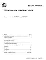
Figure 1.1 ControlNet Adapter Module
Diagnostic Indicators
Health indicators are located on the front panel of the adapter module,
See Figure 1.1. They show both normal operation and error conditions in your
remote I/O system.
In addition, an alphanumeric display (net address/status) provides status code
indications when an error occurs during initialization or operation.
A complete description of the diagnostic indicators and status display and how
to use them for troubleshooting is explained in Chapter 5.
Network Access Port (NAP)
The network access port provides a bidirectional electrical interface for
programming, maintenance, and I/O monitoring devices in both redundant
and non-redundant connections. See Figure 1.1 connecting programming
terminals to the network using the NAP above.
ADDRESS/STATUS
ADDRESS/STATUS
B
A
A
A
A
B
OK OK
Module Network Address Switches
(accessible through top of module)
Status Display and
Net Address
Health Indicators
ControlNet Status Indicators
Diagnostic Indicators
Network Access Port (NAP)
1747-ACNR15
ControlNet Media Port
ControlNet Redundant Media Port (1747-ACNR15 only)
1747-ACN15

Publication 1747-UM003A-EN-P
Introducing the ControlNet Adapter Module 1-3
ControlNet Connectors
Cable connection to the module is through standard BNC connectors on the
module frontplate.
Figure 1.2 Redundant Media System
(1) End device supporting redundant cabling is a 1747-ACNR15.
Refer to the ControlNet Cable System Planning and Installation User Manual,
publication 1786-6.2.1 for more information.
Network Address Switch Assemblies
You must set two switch assemblies to configure your adapter module with its
unique network address. You access these switches through the top of the
module. Figure 1.3 shows the location of the switches. These switches are read
on powerup to establish the network address of the module. Network address
switch settings are described in Chapter 2.
For optimum throughput, assign sequential addresses to ControlNet nodes.
B
A
trunkline A =
trunkline B =
Terminator
Terminator
PLC-5C or SLC 5/02 or later
with 1747-SCNR
end device
(1)
end device
(1)
Terminator
Terminator

Publication 1747-UM003A-EN-P
1-4 Introducing the ControlNet Adapter Module

1 Publication 1747-UM003A-EN-P
Chapter
2
Installing Your ControlNet Adapter Module
Chapter Objectives
This chapter describes the procedures for installing your ControlNet adapter
module. These include:
• European Directive compliance
• determining power requirements
• setting the network address switches
• setting the I/O chassis switches
• installing the adapter module in the chassis
• connecting programming terminals to the network via the network access
port (NAP)
• powerup sequence
Compliance to European
Union Directives
For general installation guidelines, see SLC 500 System Installation
Recommendations on page B-6. If this product has the CE mark it is approved
for installation within the European Union and EEA regions. It has been
designed and tested to meet the following directives.
EMC Directive
This product is tested to meet Council Directive 89/336/EEC Electromagnetic
Compatibility (EMC) and the following standards, in whole or in part,
documented in a technical construction file:
• EN 50081-2
EMC - Generic Emission Standard, Part 2 - Industrial Environment
• EN 50082-2
EMC - Generic Immunity Standard, Part 2 - Industrial Environment
This product is intended for use in an industrial environment.

Publication 1747-UM003A-EN-P
2-2 Installing Your ControlNet Adapter Module
Low Voltage Directive
This product is tested to meet Council Directive 73/23/EEC Low Voltage, by
applying the safety requirements of EN 61131-2 Programmable Controllers,
Part 2 - Equipment Requirements and Tests.
For specific information required by EN 61131-2, see the appropriate sections
in this publication, as well as the following Allen-Bradley publications:
•
Industrial Automation Wiring and Grounding Guidelines For Noise
Immunity, publication 1770-4.1
•
Automation Systems Catalog, publication B111
Determining Power
Requirements
The ControlNet adapter module requires a maximum backplane current of
900 mA at 5V dc. Remember to add this amount to other current
requirements for your I/O chassis.
Setting the Network
Address Switches
The switches on the top of the adapter module determine the network address
of the adapter. The two switches are:
• the ten’s switch
• the one’s switch
The combination of these switches allows selection of network addresses from
01 to 99.
Figure 2.1 Setting the Network Address
NOTE
00 is an invalid number.
Ten’s
Selection
One’s
Selection

Publication 1747-UM003A-EN-P
Installing Your ControlNet Adapter Module 2-3
Installing the Adapter
Module in the Chassis
Once you’ve set the appropriate switch assemblies for your adapter module,
follow these procedures for installation.
Refer to the Industrial Controller Wiring and Grounding Guidelines, Publication
1770-4.1 for proper grounding and wiring methods to use when installing
your module.
1. Remove power from the I/O chassis before inserting (or removing) the
module.
2. Align the circuit board with the chassis card guide in the left slot.
3. Slide the module into the chassis until the top and bottom latches are
latched. To remove the module, press the releases at the top and bottom
of the module and slide it out.
4. Press firmly and evenly to seat the module in its backplane connectors.
ATTENTION
!
!!
!
Remove system power before removing or installing your
module in the I/O chassis. Failure to observe this warning
could damage module circuitry and injure people.
ATTENTION
!
!!
!
Do not force the module into the backplane connector. If
you cannot seat the module with firm pressure, check the
alignment. Forcing the module can damage the backplane
connector or the module.
Card Guide
Power
Supply
Latch

Publication 1747-UM003A-EN-P
2-4 Installing Your ControlNet Adapter Module
Connecting Your Adapter to the ControlNet Network
You connect your 1747-ACN15 or -ACNR15 adapter module to a
ControlNet network via taps. These taps are available:
1. Remove the tap’s dust cap (located on the straight or right angle
connector).
Straight T-tap
Straight Y-tap
Right-angle T-tap Right-angle Y-tap
1786-TPS 1786-TPYS
1786-TPR
1786-TPYR
IMPORTANT
Taps contain passive electronics and must be purchased
from Allen-Bradley for the network to function properly.
If your node
supports:
Connect the tap’s straight or right angle connector:
Non-redundant media to the channel A connector on the 1747-ACN15 or
1747-ACNR15 (channel B on the 1747-ACNR is not used)
(1)
(1)
While both channels are active, Allen-Bradley recommends using channel A for non-redundant media.
Redundant media • from trunkline A to channel A on the 1747-ACNR15
• from trunkline B to channel B on the 1747-ACNR15
ATTENTION
!
!!
!
Do not allow any metal portions of the tap to contact any
conductive material. If you disconnect the tap from the
adapter, place the dust cap back on the straight or right
angle connector to prevent the connector from accidentally
contacting a metallic grounded surface.

Publication 1747-UM003A-EN-P
Installing Your ControlNet Adapter Module 2-5
2. Remove and discard the dust caps from the adapter BNC jacks.
3. Connect this tap’s straight or right angle connector to the BNC
connector on the adapter.
4. For redundant adapters (1747-ACNR15), remove (and save) the dust
cap located on the straight or right angle connector of the designated tap
on the second segment (segment 2).
5. Connect this tap’s straight or right angle connector to the BNC
connector on the adapter.
After terminating your segments, connect the node to the network.
IMPORTANT
To prevent inadvertent reversal of the tap connections
(resulting in incorrect LED displays and troubleshooting),
check the tap drop cable for a label indicating the attached
segment before making your connection.
segment 1
Tap
dust cap
segment 2
tap
dust cap
segment 1
tap
segment 2
tap

Publication 1747-UM003A-EN-P
2-6 Installing Your ControlNet Adapter Module
Connecting Programming
Terminals to the Network
via the NAP
You can connect programming terminals to the ControlNet network by
connecting to the network access port (NAP). Two methods are shown below.
Using 1784-KTC or -KTCx Communication Card and NAP
Programming Terminal
1784-KTC or
-KTCx
1786-CP
(1)
ControlNet
product
ControlNet network
Using 1770-KFC Communication Interface and NAP
Programming Terminal
1770-KFC
1786-CP
(1)
Serial or Parallel
Connection
ControlNet
product
ControlNet Network
(1) The 1786-CP cable can be plugged into any ControlNet product’s NAP to provide
programming capability on the ControlNet network. A programming terminal connected
through this cable is counted as a node and must have a unique address.
ATTENTION
!
!!
!
Use the 1786-CP cable when connecting a programming
terminal to the network through NAPs. Using a
commercially available RJ-style cable could result in
possible network failures.

Publication 1747-UM003A-EN-P
Installing Your ControlNet Adapter Module 2-7
Powerup Sequence
There are three health indicators on the module. The LED on the right
(labeled “OK”) is the generic module health indicator. The LED in the middle
(labeled “A”) is the health indicator of cable A. On the 1747-ACNR15, the
LED on the left (labeled “B”) is the health indicator for cable B. In addition,
the alphanumeric display can display module status. The following describes
the normal power-up sequence for the adapter module. (Refer
to Troubleshooting With the Status Indicators and Status Display on page 5-1
and ControlNet Status Indicators on page 5-3 for explanation of the LED’s
and alphanumeric display.)
1. Apply power to the chassis - notice that all three health indicators should
be off and the status window indicates “POST” (Power On Self Test).
2. After “POST”, the status window displays the sequence “0000”, “1111”,
“2222”, through “9999”. During this time, the A and B LEDs are off
and the OK LED toggles between red and green; this happens so fast,
the OK LED appears amber.
3. The series and revision levels are then displayed in the status window. A
series A revision level B module would display “A/B”. During this time,
the A and B LEDs are off and the OK LED toggles between red and
green; this happens so fast, the OK LED appears amber.
4. After the operating system is loaded and initialized, the status window
and the LEDs indicate the status of the module and its connections to
the cable(s). If the module address is not zero and a valid ControlNet
connection is made to either channel A or B, the status window toggles
between “ACTV” (Active) and the module node address (“A#02”, node
address number 2). If there are no active connectors, the status window
displays “IDLE”.
5. If there is a hardware problem of any kind, the health LED turns red and
the status window toggles between “FATL” and up to four alphanumeric
characters. The “FATL” indicates that there was a fatal error and the
characters indicate what the error is.
For detailed information on planning and installing your ControlNet system,
refer to Related Publication on page P-1.
ADDRESS/STATUS
B
A
OK
Status
Health Indicators
Channel A and B
indicators

Publication 1747-UM003A-EN-P
2-8 Installing Your ControlNet Adapter Module
/