Page is loading ...

System V900114
2012-2010 Dodge 25-3500 4X4 Pickup, Cab & Chassis
6.7L Cummins Diesel
System V900116
2012-2011 Dodge 45-5500 Cab & Chassis
6.7L Cummins Diesel
www.vmacair.com
VR70 UNDERHOOD
AIR COMPRESSOR
INSTALLATION MANUAL


VMAC – Vehicle Mounted Air Compressors
Toll Free: 1-888-241-2289
Fax: 1-250-740-3201
1
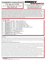
Installation Manual for VMAC
System V900114
2012-2010 Dodge 25-3500 4X4 Pickup, Cab & Chassis
6.7L Cummins Diesel
System V900116
2012-2011 Dodge 45-5500 Cab & Chassis
6.7L Cummins Diesel
General Information..................................................................... 3
Before You Start ....................................................................... 3
Part 1: System Identification and Warnings ............................ 4
Part 2: Preparing for Installation ............................................... 6
2.1 Preparing for Installation .................................................... 6
Part 3: Installing the Tank .......................................................... 8
3.1 Assembling and Installing the Brackets ............................. 8
3.2 Installing the Tank Assembly .............................................. 9
Part 4: Installing the Cooler and Compressor ......................... 10
4.1 Installing the Oil Cooler ...................................................... 10
4.2 Installing the Main Bracket and Compressor ..................... 12
4.3 Connecting the Hoses ........................................................ 16
4.4 Completing the Installation ................................................. 17
4.5 Adding Oil to the System .................................................... 21
Part 5: Installing the Control Components .............................. 22
5.1 Installing the Control Box and Throttle Control .................. 23
5.2 Connecting the Wiring ........................................................ 23
5.3 Completing and Testing the Installation ............................. 27
Part 6: Finishing the Installation ................................................ 28
6.1 Before Starting the Engine Checklist.................................. 28
6.2 After Starting the Engine Checklist .................................... 28
6.3 Setup, Performance Testing and Adjustments ................... 29
6.4 Auxiliary Air Receiver ......................................................... 30
Accessory Products from VMAC ............................................... 31

VMAC – Vehicle Mounted Air Compressors
Toll Free: 1-888-241-2289
Fax: 1-250-740-3201
2
!
Document 1930162
Installation Manual for VMAC System V900114/V900116
V900114 2012-2010 Dodge 25 - 3500 4x4 Pickup, Cab & Chassis
6.7L Cummins Diesel
V900116 2012-2011 Dodge 45 – 5500 Cab & Chassis 6.7L
Cummins Diesel
Changes and Revisions
Version
Revision Details
Revised by/date
Checked by/date
Reviewed by/date
Implemented
G
ECN 12-009
SAR 17 Jan 2012
NC 24Jan 2012
N/A
24 Jan 2012
H
ECN 12-140
SAR 02 Oct 2012
MH 10Oct 2012
N/A
10 Oct 2012
J
ECN 13-013
SH 23 Jul 2013
SM 13Sep2013
N/A
16 Sep 2013
K
ECN 13-120
JR 14 Mar 2014
MH 24 Mar 2014
DB 24 Mar 2014
01 May 2014
Important Information
The information in this manual is intended for certified VMAC
installers who have been trained in installation procedures and for
people with mechanical trade certification who have the tools and
equipment to properly and safely perform the installation. Do not
attempt this installation if you do not have the appropriate
mechanical training, knowledge and experience.
Follow all safety precautions for underhood mechanical work. Any
grinding, bending or restructuring operations for correct fit in modified
trucks must follow standard shop practices.
All hoses, tubes, and wires that are rerouted or shifted
during installation must be secure so that they do not
contact excessively hot areas or sharp edges. Where
possible use, rubber coated P-clips. Follow the routing
suggestions in this manual and cover all hoses with the
supplied plastic loom.
These instructions are a general guide for installing this system on
standard production trucks and do not contain information for
installation on non-standard trucks. This system may not fit special
order models or those that have had other changes without
additional modifications. If you have difficulty with the installation,
contact VMAC.
The VMAC warranty form must be completed and mailed or faxed to
VMAC at the time of installation for any subsequent warranty claim to
be considered valid. Copyright 2010
All trademarks used in this manual are the property of the respective copyright holder.
The contents of this manual may not be reproduced in any form without the express
written permission of VMAC, 1333 Kipp Road, Nanaimo, BC V9X 1R3.
Printed in Canada

VMAC – Vehicle Mounted Air Compressors
Toll Free: 1-888-241-2289
Fax: 1-250-740-3201
3
General Information
Before You Start
Read this manual before attempting installation so that you can
familiarize yourself with the components and how they fit on the
truck. Identify variations for different model years and different
situations that are listed in the manual. Open the package, unpack
the components and identify them.
All fasteners must be torqued to specifications. Use manufacturers
torque values for OEM fasteners. Apply Loctite 242 or equivalent on
all engine-mounted fasteners. Torque values are with Loctite applied
unless otherwise specified.
STANDARD GRADE 8 NATIONAL COARSE THREAD
Size
1/4
5/16
3/8
7/16
1/2
9/16
5/8
¾
Foot-pounds (ft-lb)
9
18
35
55
80
110
170
280
Newton meter (N•m)
12
24
47
74
108
149
230
379
STANDARD GRADE 8 NATIONAL FINE THREAD
Size
3/8
7/16
1/2
5/8
¾
Foot-pounds (ft-lb)
40
60
90
180
320
Newton meter (N•m)
54
81
122
244
434
METRIC CLASS 10.9
Size
M8
M10
M12
M14
M16
Foot-pounds (ft-lb)
19
41
69
104
174
Newton meter (N•m)
25
55
93
141
236
Hose Information
Depending on other installed equipment, it might be necessary to
move the air/oil separation tank from its intended location. The hoses
used in VMAC compressor systems have a specific inner liner that is
compatible with our compressor oil. Use of hoses other than those
supplied or recommended by VMAC may cause compressor damage
and may void your warranty. Please contact VMAC for replacement
hoses and further information.

VMAC – Vehicle Mounted Air Compressors
Toll Free: 1-888-241-2289
Fax: 1-250-740-3201
4
Part 1: System Identification and
Warnings
The System Identification Number Plate must be attached to the
truck at the time of installation. This plate provides information which
allows VMAC to assist in customer inquiries and the ordering of
parts. Place the system identification number plate in an appropriate
area, close to the compressor. Mark and drill two 7/64 inch holes
then secure the plate with self-tapping screws.
As part of the installation process, ensure that the safety and
operational instruction decal is affixed in an obvious location so that
it can be seen by truck operators (Figure 1.1).
Figure 1.1

VMAC – Vehicle Mounted Air Compressors
Toll Free: 1-888-241-2289
Fax: 1-250-740-3201
5
□ To alert any technicians that may service the vehicle, affix the
servicing caution/contact label in the engine compartment near
the hood latch in a visible location. Thoroughly clean the
selected area before affixing the label (figure 1.2)
Figure 1.2
To order parts, contact your VMAC dealer. Your dealer will ask for
the VMAC serial number, part number, description and quantity. To
locate your nearest dealer, call 1-888-241-2289.

VMAC – Vehicle Mounted Air Compressors
Toll Free: 1-888-241-2289
Fax: 1-250-740-3201
6
Part 2: Preparing for Installation
Preparation for installation is very important. Missing an item can
cause problems in the installation or even damage to components.
Check off each item as it is completed so that you do not miss any
preparation steps.
2.1 Preparing for Installation
□ Disconnect the battery terminals.
□ Remove the air cleaner assembly and the passenger side
intercooler tube.
□ Drain the coolant and remove the lower radiator hose (save for
use later).
□ Disconnect the fan clutch wire and remove it from the mounting
clips
□ Remove the fan and the fan shroud. (RH Thread).
□ Loosen the OEM crank pulley bolts but do not remove them.
Now release the OEM belt from the OEM tensioner. Remove the
OEM belt.
□ Remove the OEM crank pulley and scrape off the clear coat from
the inside front face of the hub. Discard the locking plate.
□ Remove the plug from the passenger side of the cylinder head
(Figure 2.1). Save this plug as it will be re-used later. Use thread
sealant on NPT fittings. Install the supplied pipe nipple, and tee
fitting in the cylinder head port. Face the tee fitting towards the
passenger side of the truck, and install the hose barb in the tee.
□ Remove the sway-bar mounts from the frame and allow the sway
bar to drop.

VMAC – Vehicle Mounted Air Compressors
Toll Free: 1-888-241-2289
Fax: 1-250-740-3201
7
Remove this plug
Figure 2.1

VMAC – Vehicle Mounted Air Compressors
Toll Free: 1-888-241-2289
Fax: 1-250-740-3201
8
Part 3: Installing the Tank
The tank will mount on the passenger side of the vehicle between
the two cab mounts.
Figure 3.1
3.1 Assembling and Installing the Brackets
□ Place the tank on a workbench with the front (oil filter end) of the
tank to your left and remove the oil filter.
□ Remove the two 1/4 inch pinch bolts from the C-clamps. Expand
the clamps slightly and slide them over the front of the tank.
□ Position the front clamp right behind the weld on the filter end of
the tank and the rear clamp approximately 18 inches from the
front weld.
□ Place the two formed tank strap mounts under the C-clamps with
the ends with threaded holes facing you.

VMAC – Vehicle Mounted Air Compressors
Toll Free: 1-888-241-2289
Fax: 1-250-740-3201
9
□ Apply Loctite and insert 5/16 inch bolts with flat washers into the
bottom hole on each bracket, install the nuts but do not tighten.
□ Install the 1/4 inch pinch bolts into the C-clamps so that the
heads of the bolts face toward you, apply Loctite and install the
nuts but do not tighten.
□ Rotate the tank so that the directional arrow on the end of the
tank is parallel to the workbench and faces toward you.
□ Install a 3/4 inch fitting (not supplied) in the back of the tank.
□ Apply Loctite and insert 5/16 inch bolts through the C-clamps
and the mount brackets, install the nuts but do not tighten.
□ Check tank alignment then tighten the C-clamp bolts.
□ Slide the tank all the way up on the tank mount brackets (away
from you) and tighten the mounting bolts.
3.2 Installing the Tank Assembly
□ Insert 3/8” bolt through the tank flat bar backing strap and route
the bolt over the top of the frame so that the flat bar is on the
inside of the frame rail (Figure 3.1). Apply Loctite to the upper
tank strap bolts.
□ Support the tank body in position against the frame rail with the
tank strap mounts on the outside of the frame rail and thread the
top 3/8” bolt into the tank strap mount.
□ Adjust the tank for the best fit and install the lower 3/8” tank strap
bolts and nuts. Apply Loctite to the lower tank strap bolts.

VMAC – Vehicle Mounted Air Compressors
Toll Free: 1-888-241-2289
Fax: 1-250-740-3201
10
Part 4: Installing the Cooler and
Compressor
4.1 Installing the Oil Cooler
□ Measure the inside diameter of both ends of the OEM radiator
hose. If the ID of both ends measure 2”, cut 2 sections out of the
hose as shown in figure 4.1. If the ID of the engine side
measures 2” and the radiator side measures 1.75”, use the
supplied VMAC radiator hoses.
Figure 4.1
□ Install cooler in engine bay on the passenger side beside engine,
below where air cleaner sits. Tab on cooler will be bolted to the
top of the body lift tab above passenger side frame. The cooler
tab faces forward with oil ports facing up (Figure 4.2).

VMAC – Vehicle Mounted Air Compressors
Toll Free: 1-888-241-2289
Fax: 1-250-740-3201
11
(Long hose)
(Short hose)
Figure 4.2
□ Attach the short elbow hose to the radiator and front spigot of
cooler. Attach the long hose to the engine and rear spigot of the
cooler (Figure 4.2).
□ Install supplied bolt through cooler with washer and nut on
bottom side of the body lift tab. Secure hoses with supplied hose
clamps and tighten bolt to specifications.
□ Connect the supplied 3/4 inch heater hose to the fitting on the oil
cooler, route it up the passenger side of the engine and connect
it to the 3/4 inch hose barb in the cylinder head. Make sure that
it does not contact any sharp surfaces or interfere with any belts
or moving components by securing with nylon ties and supplied
hose clamps.
□ Disconnect the small rubber hose on the upper passenger side
of the primary radiator. Fill the coolant system at the reservoir
tank, using the disconnected hose as an air bleed. Once coolant
is seen coming out of the hose and/or port on the radiator, re-
connect the hose and finish filling the reservoir to the marked
level.

VMAC – Vehicle Mounted Air Compressors
Toll Free: 1-888-241-2289
Fax: 1-250-740-3201
12
□ Once the air is purged from the system, install the OEM plug
(from the cylinder head) in the top of the tee fitting installed
during section 2.1 (using thread sealant).
4.2 Installing the Main Bracket and Compressor
□ Lock the tensioner in the loaded position with an M10 x 75mm
long bolt supplied, (Figure 4.5).
□ Remove the idler from the VR main bracket.
□ Loosen the two bottom bolts on the side of the air conditioning
compressor.
□ Install M12 washers on M12 bolts.
□ Insert the short M12 bolt through the rear mount. Place the
bracket in position on the engine so that you can see how it will
mount once the compressor has been attached (Figure 4.3.)
Angle the front of the bracket up during installation to hook the
front stud over the oil pan on the front of the engine.
Compressor, idler and tensioner left off for clarity
Short M12 bolt
M12 washer
M12 washer
Long M12 bolt
Air conditioning
compressor bolt
mount locations
Figure 4.3
If the bracket does not fit correctly make sure that the
dowel pin in the air conditioning mounting bracket against
the front of the block is bottomed-out by using a pry-bar to
push it into place (Figure 4.4).

VMAC – Vehicle Mounted Air Compressors
Toll Free: 1-888-241-2289
Fax: 1-250-740-3201
13
Pin Pry-bar
Oil pan
Figure 4.4
□ Install the M12 bolts just finger tight (longest in the front and
shortest in the rear) and check to make sure that the bracket is
flush against the block. Once you have checked the fit, remove
the bracket.
□ Install the compressor on the bracket using the two hex head
bolts and the countersunk bolt. Use Loctite and tighten securely.
□ Ensure that the supplied 5/16” washer is installed on the hex
head bolt that is closest to the front of the compressor and
engine.
□ Apply Loctite and insert the rear M12 bolt through the bracket, lift
the compressor-bracket assembly up under the AC compressor
and angle the front of the bracket over the front of the oil pan so
that the bracket is “hung” in position.
□ Apply Loctite and insert the front M12 bolt, lift the bracket into
position and thread the bolt into the engine.
□ Thread the rear M12 bolt into the engine. Tighten both M12 bolts
then tighten the bottom AC bolts against the main bracket.
□ Apply Loctite and install the M6 tensioner stop bolt (Fig 4.5).

VMAC – Vehicle Mounted Air Compressors
Toll Free: 1-888-241-2289
Fax: 1-250-740-3201
14
!
!
The tensioner stop bolt must be installed after the
bracket is mounted on the engine.
Figure 4.5
□ Place the OEM crank pulley on the front of the crankshaft and
rotate it to align it with the locating pin. Route the belt as per
(Figure 4.6) but leave the belt loose.
Do not tension the OEM belt before the OEM crank
bolts are torqued.
□ Place the VR pulley in front of the OEM crank pulley and align it
with the locating pin.
without air conditioning with air conditioning
Figure 4.6

VMAC – Vehicle Mounted Air Compressors
Toll Free: 1-888-241-2289
Fax: 1-250-740-3201
15
□ Apply Loctite to the four OEM bolts and install them through the
two pulleys into the crankshaft. Torque the crank pulley bolts to
69 ft-lbs.
□ Check the OEM belt routing diagram for the correct installation
(Figure 4.6).
□ Tension the OEM belt.
□ Place the idler on the main bracket (Figure 4.7). Apply Loctite
and fasten it in position with the M10 bolt.
Idler
Main bracket
M10 bolt
Figure 4.7
□ Install the VR compressor belt (Figure 4.8) and remove the
M10 tensioner lock bolt from the bracket. Discard this bolt as
it will not be used again.

VMAC – Vehicle Mounted Air Compressors
Toll Free: 1-888-241-2289
Fax: 1-250-740-3201
16
Figure 4.8
4.3 Connecting the Hoses
□ Connect the straight end of the 3/4-inch hose to the back of the
compressor. Route the hose up and over the engine cross-
member, and the engine mount, then down between the inner
fender and frame. Run the hose along the frame rail and connect
it to the matching fitting on the front of the tank.
□ Connect the 1/2 inch oil fill hose with the straight ends to the
fitting on the bottom of the inlet control valve and route it up
behind the passenger side battery box.
□ Connect the straight end of the longest 1/2 inch hose (with the
90 degree fitting) to the matching fitting (furthest from frame) on
the tank. Route the hose along the passenger side frame rail and
attach the 90 degree fitting to the passenger side fitting on the
top of the cooler.
□ Connect the shortest 1/2 inch oil hose to the matching fitting on
the compressor and the fitting on the top of the cooler. If needed,
loosen the locknut on the fitting and rotate it to attach the hose.
Tighten the locknut and make sure the hose clears all objects.

VMAC – Vehicle Mounted Air Compressors
Toll Free: 1-888-241-2289
Fax: 1-250-740-3201
17
!
!
□ Insert the 1/4 and 3/16 tubes into the fittings on the back of the
tank and cover them with high temperature loom. Route them to
clear any moving or high temperature components and connect
them to the matching fittings on the inlet control valve.
□ Drill a hole in the battery box just above the battery to secure the
oil fill hose and fitting (Figure 4.9).
□ Attach the hose to the supplied oil fill fitting and secure it to the
back of the passenger side battery box with the supplied P-clip.
Drill a hole
above the top
of the battery
Oil fill fitting
Figure 4.9
4.4 Completing the Installation
□ Install the fan spacer, fan, fan shroud and intercooler tube.
You may need to notch the lip on the bottom of the fan
shroud to clear the tensioner bolt during re-installation.
All hoses, tubes, and wires that are rerouted or shifted
during installation must be secure so that they do not
contact excessively hot areas or sharp edges. Where
possible use rubber coated P-clips. Follow the routing
suggestions in this manual and cover all hoses with
plastic loom.

VMAC – Vehicle Mounted Air Compressors
Toll Free: 1-888-241-2289
Fax: 1-250-740-3201
18
Transmission bell-housing
Engine oil pan
Bracket and hoses
Front
Figure 4.10
□ Remove the cab mount bolt behind the passenger side of the
front bumper. Insert the OEM bolt through the hole in the filter
assembly mount bracket and install the filter assembly with the
hose connection fitting pointing down (Figure 4.11). Adjust the
position of the filter assembly so that it does not touch any body
parts and tighten the bolt.
/