Page is loading ...

Service Manual
Main: (800) 956-6668
Local: (952) 890-7851
Fax: (952) 808-2775
Your Life. Your Ride.
TM
6591 W. Hwy 13
Savage, MN 55378
www.rollxvans.com
Chrysler / DoDge Minivan
2011-2014 Model Year


Service Manual
chrYSler / dodge Minivan
#13315-004
June 2014
2011-2014 Model Year

TaBle of conTenTS
Important Item Locations ...................................................................................................................... 1
Battery Information - General ............................................................................................................... 6
Battery Information - Draw Test Procedure .......................................................................................... 8
Rollx Vans Door (Motor Bar) - Troubleshooting .................................................................................... 9
Rollx Vans Door (Motor Bar) - Replacement Parts ............................................................................. 10
OEM Power Door - Troubleshooting....................................................................................................11
Door Modifications .............................................................................................................................. 12
Exhaust System.................................................................................................................................. 14
Exterior / Van Dimensions .................................................................................................................. 16
Fuel System........................................................................................................................................ 17
Front Suspension (Struts)................................................................................................................... 23
Rear Suspension ................................................................................................................................ 24
Engine Mounting (Cradle Drop) .......................................................................................................... 25
Torque Specifications (Suspension) ................................................................................................... 26
Interior..................................................................................................................................................27
Kneeler - Troubleshooting....................................................................................................................29
Kneeler - Replacement Parts...............................................................................................................30
One Touch System - Troubleshooting..................................................................................................31
One Touch System - Overview.............................................................................................................32
One Touch System - v8.0 Basic Interface............................................................................................34
One Touch System - v8.0 Advanced Interface - Setup ....................................................................... 35
One Touch System - v8.0 Advanced Interface - Debugger ................................................................ 36
One Touch System - v8.0 Error Codes ............................................................................................... 38
One Touch System - Relay Board Troubleshooting ........................................................................... 41
In The Floor - Troubleshooting ........................................................................................................... 43
In The Floor - Replacement Parts ...................................................................................................... 44
Folding Ramp - Troubleshooting ........................................................................................................ 45

TaBle of conTenTS
Folding Ramp - Replacement Parts ................................................................................................... 46
Folding Ramp - Motor Install / Removal and Adjustment ................................................................... 49
Rear Heat & Air................................................................................................................................... 51
Remote System - Troubleshooting ..................................................................................................... 52
Remote System - Location & Wiring .................................................................................................. 53
Seat Detector - Location & Description .............................................................................................. 54
Seat Wiring - Driver’s Side (2011-2014)..............................................................................................55
Seat Wiring - Passenger’s Side (2011-2012) ..................................................................................... 63
Seat Wiring - Passenger’s Side (2013-2014) ..................................................................................... 69
One Touch - Wiring (With Door Open Limit Switch)............................................................................73
One Touch - Wiring (With Door Detector)............................................................................................75
One Touch - Wiring (No Can Bus).......................................................................................................77
One Touch - Wiring (With Wing Window Interface).............................................................................79
Rollx Vans Power Door (Motor Bar) - Wiring ..................................................................................... 81
Maintenance Information .................................................................................................................... 83
Warranty ............................................................................................................................................. 84

iMPorTanT iTeM locaTionS
Page 1
One Touch Controller
(OTC) Board
OTC RelayBoard
Kneeler
Passenger Sliding
Door Open Switch
(Before 8/26/2013)
Rear Heat Connections
Rear A/C Connections
OTC Remote
Receiver
OTC fuse panel
(Under Glove Box)
Passenger
Seat
Detetector
Rear Heat
and Air Unit
Driver Seat
Detector
OTC
Main Fuse
Rollx Vans Main Wire Harness
(Ceiling Along Passenger’s Side)
ITF Ramp Access
Panel
Power Seat
Connector(s)
Power Seat
Connector
OEM Main Wire Harness
(Floor Along Driver’s
Side)
Neutral Safety
Signal Splice
ITF Ramp Override
Switch
OTC Remote
Programming
Switch
Rear Heat & A/C Front
Connections
Door Detector
(
after 4/15/2014
)
(
after 8/26/2013
)
Wing Window Interface
(
after 4/15/2014
)

iMPorTanT iTeM locaTionS
Page 2
OTC Remote Receiver
Rollx Vans Main Wire HarnessOEM Wire Harness
Main Fuse
(Engine Compartment)
OTC Fuse Panel
(Under Glove Box - Must Pull Back Fabric)
Passenger Sliding Door Open Switch
Rollx Vans Remote
Power Tie Down
(If Equipped)
Ignition Hot
Vans are equipped with a Ignition Hot and
Neutral Safety Panel to allow for quick
connection. See OTC Wiring for more
information.
6way controller
(If Equipped)
Neutral Safety
Used Before 8/26/2013
6way Seat Fuse
(40 Amp)
(If Equipped)
Main OTC Fuse
(40 Amp)
Rear Heat & A/C
Unit
Runs Along Driver’s
Side Floor
Runs Along Passenger’s
Side Ceiling

iMPorTanT iTeM locaTionS
Page 3
Kneeler
OTC Board
Rear AC (Rear Connections)
(Behind Rear Right Tire)
Rear Heat (Rear Connections)
(Right Rear Tire)
ITF Ramp Access Plate
OTC Relay Board
(Behind Rear Passenger Quarter Panel)
Rear Heat & A/C (Front Connections)
(Under Passenger’s Side Front Seat Area)
Kneeler and One Touch Controller
Rear Heat
Rear A/C
Universal Door Detector
Used After 8/26/2013
(behind panel)

iMPorTanT iTeM locaTionS
Page 4
Passenger’s Door Detector (Built After 4/15/2014)
(On Passenger’s C-Pillar)
Wing Window Interface (Built After 4/14/2014)
(Behind Rear Heat & Air Unit)
Neutral Safety Signal
ITF Ramp Override Switch
OTC Remote Programming Switch
*See OTC WIRING for diagram
NOTE:
Rollx V
ans taps into the
“TRS T3 SIGNAL” at the
“TRANSMISSION SOLENOID
PRESSURE SWITCH” to pick up
the Neutral Safety signal
Driver’s Power Seat Connector
(Passenger’s Same)

Page 5
iMPorTanT iTeM locaTionS
RED (12V CONSTANT)
PK / YL
(OEM IGNITION HOT)
PK / GN (12V IGNITION HOT)
Rollx Vans Ignition Hot & Neutral Safety Board Wiring
2008-2013 Chrysler Minivans (built after 5/28/2009)
TAPS INTO OEM IGNITION
HOT (PK/GN WIRE) THAT IS
LOCATED BEHIND THE CENTER
BEZEL GOING INTO THE RADIO
Power Folding Rear Sofa
If the van is equipped with a Power Folding Rear Sofa, Rollx Vans disables the FOLD/TAILGATE
SWITCH MUX which would allow the seat to be stowed into the floor. Rollx Vans cuts the LG/TN wire
at the switch.
Pin Wire Color Gauge Function
1 NO CONNECTION
2 LG/YL 22 SEAT SWITCH SELECTOR SIG
3 LG/TN 22 SEAT FOLD SIGNAL
4 LG/DB 22 SEAT STOW SWITCH SIGNAL
5 LG/VT 22 FOLDING SEAT SWITCH RET
6 NO CONNECTION
7 NO CONNECTION
8 NO CONNECTION
1 AMP
REMOTE
DOOR DETECTOR
CONTROLLER PWR
1 AMP
1 AMP
Nuetral
Safety
Ignition
Hot
FUSE PANEL
(BEHIND GLOVE BOX)
*
2
D
N
R
P
GN/DB
Neutral Safety
1
4
8
13
17
21
3
7
23
20
16
(OEM CAV 9)
*(To Inition Hot)
located under
steering column
12
RD (8 GA.)
BK (8 GA.)
FUSE
40A
-
+
RD (8 GA.)
Cut
1
4
8
5

Page 6
BaTTerY inforMaTion - general
The following procedure should be used to test the current draw from any battery
used in our vans.
1) Insure the battery is fully charged.
2) Remove the key from the ignition switch.
3) Close all the doors including the sliding doors and the rear tailgate.
4) Close all the windows including the rear vent windows.
5) Remove the negative (Black) cable from the battery and move it to a safe location
away from both the positive (Red) and negative terminals of the battery.
6) Acquire a Digital Multimeter with a 20 Amp current range function. NOTE: A
standard van can draw between 15 and 17 amps of current when it is first powered
up (When the battery is reconnected). You must use a multimeter with a 20 Amp
range. Using a Multimeter with a lower current range function will damage the
meter if it does not have an internal fuse. If it has an internal fuse, it will be blown.
NOTE: DO NOT RUN THE ROLLX VANS OTC OR TRY TO START THE VAN WHEN
YOU HAVE THE METER CONNECTED! YOU WILL DAMAGE THE METER!
7) Place the function switch of the Multimeter in the 20 Amp Current Measurement
position.
8) Connect the negative (black) probe (wire lead) to the black jack on the multimeter.
9) Most multimeters have more than one red jack for the positive (red) probe. They
usually have one jack for measuring AC & DC voltage and resistance, along with a
second Jack for measuring AC & DC Current. Some multimeters have more than
one red jack for measuring current (three red jacks total). As an example a meter
might have two red jacks, one rated for 200 Milliamps and a second for 20 Amps.
You should use the 20 Amp plug (or the one with the largest rating).
10) Acquire two test jumpers with alligator clips (Radio Shack # 278-002). Attach one
jumper to the positive (Red) probe and the other to the negative( Black) probe.
11) Turn the multimeter on.
12) Attach the other end of the jumper clipped on the positive (red) meter probe to the
disconnected battery cable.
NOTE: Polarity does not matter much when measuring current. A positive current
is the same as negative current. Disregard the polarity indicator on the multimeter
during these tests.
13) Attach the jumper on the negative (black) meter probe to the negative terminal of
the battery.
NOTE: YOU MAY GET A SPARK WHEN YOU ATTACH THE JUMPER. THIS IS
NORMAL. ALL THE CURRENT BEING USED BY THE VAN IS NOW RUNNING
THROUGH THE METER. AS MUCH AS 15-17 AMPS).

Page 7
BaTTerY inforMaTion - general
14) The Multimeter should now show a reading. Keep your eye on the meter and
watch the draw. A typical van can have from 18 to 28 computer modules in it.
They are all woke up when power was applied to the van by attaching your meter
probes. As you watch the current reading you will note that it will start to fall. This
happens as the computers in the van decide they are not needed and put
themselves to sleep. Chrysler says it can take up to thirty minutes for everything
to go into sleep mode.
The current should drop in stages similar to the sequence below:
a. The reading will start as high as 15-17 amps for a short period of time.
b. It then fall to 6-8 amps for a short time.
c. Then 1 to 1.5 amps for a period of time.
d. It will then settle on around .800 amps (800 Milliamps) for a while.
e. Then it may drop to .100 to .200 amps (100 to 200 Milliamps) for period of
time.
f. Finally it will drop all the way into sleep mode, .040 to .100 amps (40 to 100
Milliamps) and will stay there until the van is woke up.
g. Note: The values you will see will vary from van to van, from van type to
type and by the number and type of accessories installed on the van. The
important thing is that it drops to a value less the 100 Milliamps (.100
Amps) for a standard van when it goes into sleep mode.
15) You can wake the van simply by opening the driver’s side door for a few seconds,
then closing it.
16) Watch the meter again to see the van go into sleep mode again. You should repeat
this test until you are satisfied the van’s “Sleep Mode” is functioning correctly.

Page 8
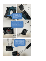
BaTTerY inforMaTion - draW TeST Procedure
This picture shows a complete setup for a Draw Test:
Note the black probe attached to the negative terminal and the red probe attached to the
negative battery cable.
This picture shows a typical multimeter. Note the current range switch settings and
current probe jack markings are all in yellow for uA (Microamps), mA (Milliamps and A
(Amps).
Also note that the meter has two Jacks for current measurement, “20A” and “uA/mA”. On
this meter, for our Draw Test, we would place the Function Switch in the “A” (for Amps)
position and plug the Red Probe into the “20A” Jack. The Black Probe always goes in the
Black Jack.

Page 9
rollX vanS door (MoTor Bar) TrouBle ShooTing
Symptom Possible Cause Remedy
Front passenger door is locked.
Unlock front passenger door.
Switch is stuck.
Make sure all user switches are not stuck.
Blown fuse.
Replace 30 or 15 amp blade fuse located
underneath hood near battery.
Manual release handle is not engaged. Turn handle all the way counter-clockwise.
Door will open, but ramp will not
deploy.
Door open limit switch needs adjustment.
Adjust the door open limit swtich (#7 on next
page). The switch can be accessed by the
passenger side rear speaker area (remove the
speaker first).
Door will open, but not close or
door will "jump" closed.
Ramp up limit switch is not engaged. Adjust the cam for up limit.
Gear on motor is stripped.
Replace motor.
Gear on bar is stripped. Replace gear rack (bar).
Door does not operate.
Door "ratchets" when operating
(make sure kneeler is off).
3/26/2013 2011 Trouble Shooting.xls Page 1

Page 10
rollX vanS door (MoTor Bar) rePlaceMenT ParTS
COM
COM
NC
NC
NO
NO
1
2
3
4
5
6
7
8
9
10
11
15
12
12
13
14
Rollx Vans Power Door Exploded View
Item Qty. Description Part #
1 DOOR BAR ASM (INCLUDES THE 3 FOLLOWING) 10026ASM
1 MTR BAR DOOR OPENER (RACK AND ASSEMBLY) 10026
1 WIRE HARNESS 5.5" FOR 310-1059
1 MTR 12V 10NM 10MM DOUBLE 210-1011
1 1 GEAR RACK (SPECIFY LONG OR SHORT)* 10026-4
LONG BAR
2 1 3/8 X 1 STRIP
1126318
3 1 ARM BAR (FOR MOTOR BAR) 10026-22
4 1 WIRE HARNESS 5.5" FOR 310-1059
5 1 MOTOR ONLY W/GEAR ASM (INCLUDES WIRE HARNESS AND SHIMS**)
10026-15ASM
* LONG USED BEFORE ~2001 IF NO REAR HEAT & AIR
** SHIMS ONLY NEEDED IF BEFORE ~2003 BUT ALWAYS SENT WITH MOTOR
Item Qty. Description Part #
6 1 BRKT MTR BAR LIMIT SWITCH MB1006
7 1 SWITCH DPDT (CHERRY) E19-50H
8 1 HANDLE CHROME INSIDE 6022
9 1 DOOR BRACKET A (DOOR BRACKET B - ) MB1001 (MB1002)
10 2 DOOR ARM PLATE MB1005
11 N/A MANUAL RELEASE TENSION ADJUSTMENT NA
12 N/A 1/4-20 NYLOCK NUT SHOP SUPPLY
13 2 #6 NYLOCK NUT SHOP SUPPLY
14 1 1/4-20X3/4 HEX HEAD SCREW SHOP SUPPLY
15 1 5/8-20X1 HEX HEAD SCREW (ADJUSTME NT) SHOP SUPPLY
16 1 SHIM KIT FOR DOOR OPENERS (INCLUDES ALL 3 - VARYING SIZES) 10026-12
17 2 #10-32X2 HEX HEAD (5/32) PARTIALLY THREADED SCREW SHOP SUPPLY
18 1 #10-32X2-1/2 HEX HEAD (5/32) PARTIALLY THREADED SCREW (NUT ON BACK) SHOP SUPPLY
17
18
16

oeM PoWer door TrouBleShooTing
Symptom Possible Cause Remedy
Van is NOT in park. Place van into park.
Overhead on/off switch is turned to the OFF
position.
Turn switch to ON position.
OTC program failure. Press OTC reset button.
OTC reads low voltage.
Start van's engine and press OTC reset button.
If door still does not open review OTC board
display and contact customer service.
Bad OTC board.
Press the OTC reset button and while in Idle
Mode press a user button and watch the LED.
Notice if OTC appears to be working properly.
Review error codes stored and call customer
service.
Main OTC fuse (40 amp) is blown. Replace fuse under hood by battery.
OEM overhead ON / OFF switch is OFF.
Turn switch to ON position. This switch enables /
disables the OEM buttons located on the B
pillars that Rollx Vans uses to trigger the sliding
door to open or close.
Defective OEM door opener.
Operate door manually and contact customer
service.
Ramp sliding door does NOT
attempt to CLOSE after ramp
stows.
Ramp up limit switch is not being activated
properly.
Close door manually, press OTC reset button,
and press Rollx Vans user button to operate
system again. If door still does not attempt to
close after ramp is stowed, review OTC board
display and contact customer service.
Defective door open bracket. Adjust the bracket and contact customer service.
Defective OEM door opener.
Press OTC reset button, press interior OEM
push button to see if door will close
automatically. If door still does not respond,
review OTC board display and contact customer
service.
Obstruction. Check door track for any debris and remove.
Ramp needs adjustment (Foldout only). Adjust folding ramp to stow more.
OEM door sensitivity set low. Contact local Chrysler Dealership.
Ramp sliding door opens and van
kneels, but when door is all the way
open, van unkneels and cycle
ends.
OEM Door Ajar Pin Switch (Rollx Vans Door
Close signal) is never deactivated when door
begins to open.
If the OTC thinks the door is open and closed it
will end the cycle. Examine switch / wiring.
Ramp needs adjustment (Foldout only). Adjust folding ramp to stow more.
Defective OEM cinch motor.
Operate door manually and contact customer
service.
Ramp sliding door does NOT
OPEN manually.
Door is locked.
Unlock door. When pulling door handle, pull
handle out and then slide door to open.
Ramp sliding door does NOT
OPEN manually from interior
handle, but does from exterior
handle.
Child safety lock is activated.
See OEM owner manual to deactivate child
safety lock.
Ramp sliding door closes half way
and then moves back and forth.
Stuck door open limit swith, or CAN BUSS door
opener Module.
Adjust swtich located in rear of lower door track,
or unplug module & wait 2 seconds.
Door handle is not releasing.
Pull handle to disengage latch and slide to
close.
Obstruction. Check door track for any debris and remove.
Ramp sliding door will NOT CLOSE
manually.
Ramp sliding door does NOT
OPEN with interior OEM push
buttons after pressing OTC reset
button.
Ramp sliding door attempts to
close (door motor runs) after ramp
stows, but door does not move.
Ramp sliding door kicks back when
opening or closing.
Ramp sliding door does not seal
when almost closed.
Passenger sliding door does NOT
OPEN with interior Rollx Vans user
button.
5/8/2013 2011 Trouble Shooting.xls Page 1
Note: In order to disable the OEM door from closing when the ramp is out, Rollx Vans interupts
Chryler’s CAN BUS circuit to prevent the door from getting any signal to close. The Scan tool will read
a “No Communication with the Right Rear Door Module” everytime the system deploys
the ramp. This is a normal trouble code and is to be excpected.
Page 11

Page 12
door ModificaTionS
#10277 - Rivets (9 per Door)
Inner Door Skin (Extension)
Driver Side - #B08180-D5
Passenger Side - #B08180-P5
DOOR TRACK EXT BKT UPPR 08
#B08030ASM
Needs to be painted to match van
Outer Sliding Door
#10277 - Rivets (6 per Door)
Door extension kits
part numbers and
descriptions
-B08180-D5-KIT-ITF
Door skin svc kit itf dr
-B08180-D5-KIT-FO
door skin svc kit fo dr
-B08180-P5-KIT-ITF
Door skin svs kit itf pass
-B08180-P5-KIT-FO
Door skin svs kit fo pass
OEM BOLT (3)
A#6505 480A
#B08033
‘08 LOWER DOOR ARM
(Spaceship bracket)
OEM LOWER DOOR ROLLER ARM
Passenger Side - #5020 920AB
Driver Side - #5020 921AB
Current
#B08180-DP6 - L BRKT DOOR SKIN DR/PASS 08
Before 10/20/2008
#10503 - 1”X 1” 14GA ROLLED ANGLE
CABLE POWER DOOR 2008
#AR-2008
BOLT (3) - #0115007
WASHER (3) - #1133004

Page 13
door ModificaTionS
DOOR TRACK EXT BKT LOWR 08 ASM
#B08032ASM
(#B08032-1ASM Vans Started after 7/21/2010)
(Includes Switch, Wire Harness, and Bracket)
SNAKE CONNECT BLOCK SLIDE ARM
#B08050 (Not Shown)
BUMPER, MIDDLE TRACK
#9306K14
Passenger Sliding Door Middle Track
ZOOM +
Door track kits and descriptions include OEM track and door open switch bracket
B08059asm-dr - Door track asm 08-09 dr
B08059asm-dr-2010 - Door track asm 10-13 dr
B08059asm-ps - Door track asm 08-09 ps
B08059asm-ps-2010 - Door track asm 10-13 ps
DOOR OPEN SWITCH
ASSEMBLY - #05089-003
Built Before 8/26/2013
DOOR TRACK EXT BKT LOWR 08
#B08032
(#B08032-1 Vans Started after 7/21/2010)
1/4-20X1/2” Hex Bolt
#0115001
FHSCS 1/4-20X1/2 ZB
#94222

Page 14 Page 14
eXhauST SYSTeM
Rollx Vans Exhaust
#B08201-SS
Rollx Vans begins their exhaust from the OEM Catalytic Converter (Rollx Vans does not modify the OEM
Catalytic Converter or OEM 02 Sensor). Rollx Vans Exhaust is welded to the OEM Catalytic Converter
and runs down the passenger side of the van.
Rollx Vans reuses the OEM Hangers to support the exhaust. Rollx Vans Exhuast is 2-1/4 inch diameter
aluminized tubing and replaces the OEM 2-1/2 exhaust.
OEM Hanger
Rollx Vans Weld
OEM Catalytic Converter /
O2 Sensor
Rollx Vans Exhaust
3.3L & 3.8L #B08200-SS
4.0L #B08202
3.6L #B11200-SS
Rollx Vans Weld

Page 15
eXhauST SYSTeM
Rollx Vans Exhaust continues over the rear axle and is welded to the OEM Muffler and Tailpipe.
Rollx Vans eliminates the OEM Resonator.
Rollx Vans Exhaust
#B08201-SS
OEM Muffler and
Tailpipe
Rollx Vans Weld
/