Page is loading ...

Industrial Computers for Hazardous Locations
Series H
Catalog Numbers 6181X-12P2SWX1DC, 6181X-12A2SWX1DC, 6181X-00N2SWX1DC, 6181X-12A2SW71DC,
6181X-00N2SW71DC, 6189X-MCLPS, 6189X-8GDDR3, 6189X-16GDDR3, 6189V-CFSSD8GB, 6189V-CFSSD16GB,
6189X-128GBSSD, 6189X-256GBSSD, 6189X-PCIRISER, 6189X-SUNSHIELD
User Manual
Original Instructions

Important User Information
Read this document and the documents listed in the additional resources section about installation, configuration, and
operation of this equipment before you install, configure, operate, or maintain this product. Users are required to
familiarize themselves with installation and wiring instructions in addition to requirements of all applicable codes, laws,
and standards.
Activities including installation, adjustments, putting into service, use, assembly, disassembly, and maintenance are
required to be carried out by suitably trained personnel in accordance with applicable code of practice.
If this equipment is used in a manner not specified by the manufacturer, the protection provided by the equipment may
be impaired.
In no event will Rockwell Automation, Inc. be responsible or liable for indirect or consequential damages resulting from
the use or application of this equipment.
The examples and diagrams in this manual are included solely for illustrative purposes. Because of the many variables and
requirements associated with any particular installation, Rockwell Automation, Inc. cannot assume responsibility or
liability for actual use based on the examples and diagrams.
No patent liability is assumed by Rockwell Automation, Inc. with respect to use of information, circuits, equipment, or
software described in this manual.
Reproduction of the contents of this manual, in whole or in part, without written permission of Rockwell Automation,
Inc., is prohibited.
Throughout this manual, when necessary, we use notes to make you aware of safety considerations.
Labels may also be on or inside the equipment to provide specific precautions.
WARNING: Identifies information about practices or circumstances that can cause an explosion in a hazardous
environment, which may lead to personal injury or death, property damage, or economic loss.
ATTENTION: Identifies information about practices or circumstances that can lead to personal injury or death, property
damage, or economic loss. Attentions help you identify a hazard, avoid a hazard, and recognize the consequence.
IMPORTANT Identifies information that is critical for successful application and understanding of the product.
SHOCK HAZARD: Labels may be on or inside the equipment, for example, a drive or motor, to alert people that dangerous
voltage may be present.
BURN HAZARD: Labels may be on or inside the equipment, for example, a drive or motor, to alert people that surfaces may
reach dangerous temperatures.
ARC FLASH HAZARD: Labels may be on or inside the equipment, for example, a motor control center, to alert people to
potential Arc Flash. Arc Flash will cause severe injury or death. Wear proper Personal Protective Equipment (PPE). Follow ALL
Regulatory requirements for safe work practices and for Personal Protective Equipment (PPE).

Rockwell Automation Publication 6181X-UM002B-EN-P - November 2019 3
Table of Contents
Preface
Summary of Changes . . . . . . . . . . . . . . . . . . . . . . . . . . . . . . . . . . . . . . . . . . . 7
Additional Resources . . . . . . . . . . . . . . . . . . . . . . . . . . . . . . . . . . . . . . . . . . . 8
Abbreviations. . . . . . . . . . . . . . . . . . . . . . . . . . . . . . . . . . . . . . . . . . . . . . . . . . 8
Chapter 1
Features Operating Systems . . . . . . . . . . . . . . . . . . . . . . . . . . . . . . . . . . . . . . . . . . . . . 9
Computer Options. . . . . . . . . . . . . . . . . . . . . . . . . . . . . . . . . . . . . . . . . . . . . 9
Computer Nameplate Information . . . . . . . . . . . . . . . . . . . . . . . . . . . . . 10
Hardware Features . . . . . . . . . . . . . . . . . . . . . . . . . . . . . . . . . . . . . . . . . . . . 11
Chapter 2
Install the Computer Before You Begin. . . . . . . . . . . . . . . . . . . . . . . . . . . . . . . . . . . . . . . . . . . . . . 13
Parts List . . . . . . . . . . . . . . . . . . . . . . . . . . . . . . . . . . . . . . . . . . . . . . . . . . . . . 13
Installation Precautions. . . . . . . . . . . . . . . . . . . . . . . . . . . . . . . . . . . . . . . . 14
Environment and Enclosure Information. . . . . . . . . . . . . . . . . . . . 14
European Union Directive . . . . . . . . . . . . . . . . . . . . . . . . . . . . . . . . . 14
Outdoor Installation. . . . . . . . . . . . . . . . . . . . . . . . . . . . . . . . . . . . . . . 15
Hazardous Locations . . . . . . . . . . . . . . . . . . . . . . . . . . . . . . . . . . . . . . 16
Hot Surfaces . . . . . . . . . . . . . . . . . . . . . . . . . . . . . . . . . . . . . . . . . . . . . . 18
Restricted Access Location . . . . . . . . . . . . . . . . . . . . . . . . . . . . . . . . . 19
Installation Guidelines. . . . . . . . . . . . . . . . . . . . . . . . . . . . . . . . . . . . . . . . . 19
Mounting Clearance Requirements . . . . . . . . . . . . . . . . . . . . . . . . . . . . . 20
Computer Dimensions . . . . . . . . . . . . . . . . . . . . . . . . . . . . . . . . . . . . . . . . 21
Tools for Computer Installation. . . . . . . . . . . . . . . . . . . . . . . . . . . . . . . . 22
Install the Computer . . . . . . . . . . . . . . . . . . . . . . . . . . . . . . . . . . . . . . . . . . 22
Panel Mounting Guidelines . . . . . . . . . . . . . . . . . . . . . . . . . . . . . . . . 23
Panel Cut Out Dimensions. . . . . . . . . . . . . . . . . . . . . . . . . . . . . . . . . 23
Mount the Integrated Display Computer in a Panel . . . . . . . . . . 23
Mount the Non-display Computer on a Wall . . . . . . . . . . . . . . . . 25
Connect Power . . . . . . . . . . . . . . . . . . . . . . . . . . . . . . . . . . . . . . . . . . . . . . . 26
Connect to a Network. . . . . . . . . . . . . . . . . . . . . . . . . . . . . . . . . . . . . . . . . 27
Chapter 3
Operate the Computer Operating Guidelines . . . . . . . . . . . . . . . . . . . . . . . . . . . . . . . . . . . . . . . . . 29
Touch Screen Precautions. . . . . . . . . . . . . . . . . . . . . . . . . . . . . . . . . . . . . . 30
Start the Computer. . . . . . . . . . . . . . . . . . . . . . . . . . . . . . . . . . . . . . . . . . . . 30
Restart the Computer . . . . . . . . . . . . . . . . . . . . . . . . . . . . . . . . . . . . . . . . . 31
Shut Down the Computer . . . . . . . . . . . . . . . . . . . . . . . . . . . . . . . . . . . . . 31
Adjust the Display Brightness . . . . . . . . . . . . . . . . . . . . . . . . . . . . . . . . . . 31

4 Rockwell Automation Publication 6181X-UM002B-EN-P - November 2019
Table of Contents
Chapter 4
Replace Components Accessories and Replacement Parts . . . . . . . . . . . . . . . . . . . . . . . . . . . . . 33
Voltage Precautions . . . . . . . . . . . . . . . . . . . . . . . . . . . . . . . . . . . . . . . . . . . 33
Electrostatic Discharge Precautions . . . . . . . . . . . . . . . . . . . . . . . . . . . . . 34
Pre-configuration . . . . . . . . . . . . . . . . . . . . . . . . . . . . . . . . . . . . . . . . . . . . . 34
Post-configuration . . . . . . . . . . . . . . . . . . . . . . . . . . . . . . . . . . . . . . . . . . . . 35
Tools for Component Replacement. . . . . . . . . . . . . . . . . . . . . . . . . . . . . 35
Remove the Cover. . . . . . . . . . . . . . . . . . . . . . . . . . . . . . . . . . . . . . . . . . . . . 35
Reinstall the Cover . . . . . . . . . . . . . . . . . . . . . . . . . . . . . . . . . . . . . . . . . . . . 35
Replace a Solid-state Drive . . . . . . . . . . . . . . . . . . . . . . . . . . . . . . . . . . . . . 36
Load a CompactFlash Card . . . . . . . . . . . . . . . . . . . . . . . . . . . . . . . . . . . . 37
Install an Add-in Card. . . . . . . . . . . . . . . . . . . . . . . . . . . . . . . . . . . . . . . . . 38
Replace or Add Memory Modules . . . . . . . . . . . . . . . . . . . . . . . . . . . . . . 40
Memory Configuration Guidelines. . . . . . . . . . . . . . . . . . . . . . . . . . 40
Replace or Add a Memory Module . . . . . . . . . . . . . . . . . . . . . . . . . . 40
Real-time Clock (RTC) Battery . . . . . . . . . . . . . . . . . . . . . . . . . . . . . . . . 41
Chapter 5
Set Up the UEFI Utility Set-up Utility Overview. . . . . . . . . . . . . . . . . . . . . . . . . . . . . . . . . . . . . . . . 43
Access the Set-up Utility . . . . . . . . . . . . . . . . . . . . . . . . . . . . . . . . . . . . . . . 44
Set-up Screen Overview. . . . . . . . . . . . . . . . . . . . . . . . . . . . . . . . . . . . . . . . 44
Firmware Update . . . . . . . . . . . . . . . . . . . . . . . . . . . . . . . . . . . . . . . . . . . . . 45
Firmware Configuration . . . . . . . . . . . . . . . . . . . . . . . . . . . . . . . . . . . . . . . 46
Main . . . . . . . . . . . . . . . . . . . . . . . . . . . . . . . . . . . . . . . . . . . . . . . . . . . . . 47
Advanced . . . . . . . . . . . . . . . . . . . . . . . . . . . . . . . . . . . . . . . . . . . . . . . . . 48
Chipset . . . . . . . . . . . . . . . . . . . . . . . . . . . . . . . . . . . . . . . . . . . . . . . . . . . 53
Boot. . . . . . . . . . . . . . . . . . . . . . . . . . . . . . . . . . . . . . . . . . . . . . . . . . . . . . 54
Security. . . . . . . . . . . . . . . . . . . . . . . . . . . . . . . . . . . . . . . . . . . . . . . . . . . 55
Save and Exit . . . . . . . . . . . . . . . . . . . . . . . . . . . . . . . . . . . . . . . . . . . . . . 55
Diagnostics . . . . . . . . . . . . . . . . . . . . . . . . . . . . . . . . . . . . . . . . . . . . . . . . . . . 56
AMI Rescue . . . . . . . . . . . . . . . . . . . . . . . . . . . . . . . . . . . . . . . . . . . . . . . . . . 57
Make a Backup . . . . . . . . . . . . . . . . . . . . . . . . . . . . . . . . . . . . . . . . . . . . 58
Restore OS Image From a Hidden Partition . . . . . . . . . . . . . . . . . 59
Restore OS Image From a USB Storage Drive . . . . . . . . . . . . . . . . 62
Hardware History. . . . . . . . . . . . . . . . . . . . . . . . . . . . . . . . . . . . . . . . . . . . . 66
Exit . . . . . . . . . . . . . . . . . . . . . . . . . . . . . . . . . . . . . . . . . . . . . . . . . . . . . . . . . . 67
Upgrade to a New UEFI . . . . . . . . . . . . . . . . . . . . . . . . . . . . . . . . . . . . . . . 68
Chapter 6
Troubleshoot the System Hardware Monitoring . . . . . . . . . . . . . . . . . . . . . . . . . . . . . . . . . . . . . . . . . 69
Troubleshooting . . . . . . . . . . . . . . . . . . . . . . . . . . . . . . . . . . . . . . . . . . . . . . 70
Diagnostics . . . . . . . . . . . . . . . . . . . . . . . . . . . . . . . . . . . . . . . . . . . . . . . . . . . 70
Load the System Defaults . . . . . . . . . . . . . . . . . . . . . . . . . . . . . . . . . . . . . . 71
Clear the CMOS. . . . . . . . . . . . . . . . . . . . . . . . . . . . . . . . . . . . . . . . . . . . . . 72
Ship or Transport the Computer . . . . . . . . . . . . . . . . . . . . . . . . . . . . . . . 73
Dispose of the Computer . . . . . . . . . . . . . . . . . . . . . . . . . . . . . . . . . . . . . . 73

Rockwell Automation Publication 6181X-UM002B-EN-P - November 2019 5
Table of Contents
Chapter 7
Use a Touch Screen Touch Screen Technology . . . . . . . . . . . . . . . . . . . . . . . . . . . . . . . . . . . . . 75
Resistive Touch Screen Displays . . . . . . . . . . . . . . . . . . . . . . . . . . . . 75
PCAP Touch Screen Displays . . . . . . . . . . . . . . . . . . . . . . . . . . . . . . 75
Touch Screen Operation. . . . . . . . . . . . . . . . . . . . . . . . . . . . . . . . . . . . . . . 76
Calibrate the Resistive Touch Screen. . . . . . . . . . . . . . . . . . . . . . . . . . . . 76
Chapter 8
Maintain the Computer Clean the Computer . . . . . . . . . . . . . . . . . . . . . . . . . . . . . . . . . . . . . . . . . . 77
Clean the Integrated Display . . . . . . . . . . . . . . . . . . . . . . . . . . . . . . . 77
Clean the Heatsink and Vent Holes. . . . . . . . . . . . . . . . . . . . . . . . . 77
Remove Paint and Grease from the Bezel . . . . . . . . . . . . . . . . . . . . 78
Index
. . . . . . . . . . . . . . . . . . . . . . . . . . . . . . . . . . . . . . . . . . . . . . . . . . . . . . . . . . . . . . 79

6 Rockwell Automation Publication 6181X-UM002B-EN-P - November 2019
Table of Contents
Notes:

Rockwell Automation Publication 6181X-UM002B-EN-P - November 2019 7
Preface
This manual is a user guide for 6181X Series H display and non-display industrial
computers for hazardous locations. It provides procedures to the following:
• Install the computer.
• Make computer connections.
•Operate the computer.
• Troubleshoot the computer.
Summary of Changes
This publication contains new and updated information as indicated in this table.
Topic Page
Added Cat. No. 6181X-12P2SWX1DC and footnote to the first table in the Computer Options section. 9
Revised description to 6189X-PCIRISER to the second table in the Computer Options section. 10
Added Cat. No. 6189X-SUNSHIELD to the second table in the Computer Options section. 10
Added footnote to the second table in the Computer Options section. 10
Added second sentence to introductory paragraph in Hardware Features section. 11
Added ABNT NR ratings to Important table in Environment and Enclosure Information subsection. 14
Added ratings information sentence that references Hazardous Location section. 14
Updated Product Certifications URL to rok.auto/certifications. 14
Reduced maximum distance for I/O cables from 30 ft to 3 ft, and added Ethernet cable exception. 14
Added paragraph about available Rockwell Automation® sun shield in the Outdoor Installation section. 15
Added Important table about Rockwell Automation sun shield in the Outdoor Installation section. 15
Added Cat. No. 6181X-12P2SWX1DC to Hazardous Locations table. 16
Added Important table above Hazardous Locations table. 16
Revised rating numbers and added INMETRO information in the Hazardous Locations table. 16
Converted table footnotes to the new The Following Conditions for Safe Use Apply in ATEX, IECEx, and INMETRO section. 17
Added ‘Conditions for Safe Use in North American Hazardous Locations’ subsection title. 18
Revised content to address sun shield usage in Important table in Hot Surfaces section. 18
Added DC wiring table to Installation Guidelines section. 19
Added Cat. No. 6181X-12P2SWX1DC to the table in the Panel Cutout Dimensions section. 23
Added Cat. No. 6181X-12P2SWX1DC to the table in the Mount the Integrated Display Computer in a Panel section. 23
Added cross-references to new DC wiring table in steps 2 and 3 in the Connect Power section. 26
Added cross-references to new DC wiring table in step 4 and its Important table in Connect Power section. 27
Revised Important table to specify add-in card evaluation and use. 38
Added picture of factory-installed riser card and available riser card accessory. 38
Expanded step 3 to include slot cover screw information for further use. 38
Expanded step 6 to include separate install instructions for PCIe and PCI add-in cards. 38
Added sentence about memory modules with heatsinks to Important table in Replace or Add Memory Modules section. 40
Added second sentence to Important table in the Replace or Add Memory Modules subsection. 40
Added picture of memory modules with heatsinks to step 3 in the Replace or Add Memory Modules section. 40
Added step 5 to the Replace or Add Memory Modules section. 41
Updated website and URL to return a computer for clock battery replacement. 41
Updated screen shot to include both Touch parameters in the Hardware Monitor subsection. 52
Replaced the introductory paragraph with a sentence in the Touch Screen Technology section. 75
Replaced the Driver Software section with the two touch screen display subsections. 75
Replaced Resistive Touch Screen Technology title with Touch Screen Operation title. 76
Added second paragraph to the Touch Screen Operation section. 76
Added ‘Resistive’ to the Calibrate the Resistive Touch Screen title. 76
Added Important table to the Calibrate the Resistive Touch Screen section. 76

8 Rockwell Automation Publication 6181X-UM002B-EN-P - November 2019
Preface
Additional Resources
These documents contain additional information to related products from
Rockwell Automation.
You can view or download publications at
https://www.rockwellautomation.com/global/literature-library/overview.page
.
To order paper copies of technical documentation, contact your local
Allen-Bradley® distributor or Rockwell Automation sales representative.
Abbreviations
This publication uses the following abbreviations.
Resource Description
Industrial Computer and Monitor
Specifications Technical Data, publication
IC-TD001
Provides technical specifications for the 6181X integrated display and
non-display computers for hazardous locations.
6181X Industrial Computers for Hazardous
Locations, Series H, Installation Instructions,
publication 6181X-IN002
Provides procedures to install the 6181X Series H computer and to
make connections.
Industrial Automation Wiring and Grounding
Guidelines, publication 1770-4.1
Provides general guidelines to install a Rockwell Automation industrial
system.
Abbr Meaning Abbr Meaning
AHCI Advanced Host Controller Interface PCB Printed circuit board
BIOS Basic input/output system PCDC Product Compatibility and Download
Center
CF CompactFlash PCI Peripheral component interconnect
CMOS Complementary metal oxide
semiconductor
PCIe Peripheral component interconnect
express
COM Communication (serial port interface) PELV Protective extra low voltage
DDR Double data rate (RAM) POST Power on self-test
DIMM Dual in-line memory module RAID Redundant array of independent disks
DP DisplayPort (digital display interface) RAM Random access memory
DVI Digital video interface RTC Real-time clock
EEA European Environment Agency SELV Safety extra low voltage
EMC Electromagnetic compatibility SSD Solid-state drive
ESD Electrostatic discharge TFT Thin film transistor
IEC International Engineering Consortium UEFI Universal extensible firmware interface
LAN Local area network USB Universal serial bus
NDM
Non-display model
UPS Uninterruptible power source
NEMA
National Electrical Manufacturers
Association
VGA Video graphics array
PCAP
Protective capacitive (touch screen)

Rockwell Automation Publication 6181X-UM002B-EN-P - November 2019 9
Chapter 1
Features
Operating Systems
The following Microsoft®-licensed operating systems are available:
• Windows® 7 Professional (64 bit), SP 1
• Windows 10 Internet of Things (IoT) Enterprise (64 bit)
To obtain a copy of a factory system image, contact your local technical-support
center or access the Rockwell Automation Product Compatibility and Download
Center (PCDC) at https://compatibility.rockwellautomation.com/Pages/
home.aspx.
Computer Options
Tab le 1 summarizes the options that are available for industrial computers for
hazardous locations.
Table 1 - Computer Options
Topic Page
Operating Systems 9
Computer Options 9
Computer Nameplate Information 10
Hardware Features 11
Cat. No. Model Series Display Size Touch Screen Windows OS
6181X-00N2SW71DC NDM H — 7 Professional 64 bit SP1
6181X-12A2SW71DC 1200XT 12.1 in. Resistive
6181X-00N2SWX1DC NDM — 10 IoT Enterprise 64 bit
6181X-12A2SWX1DC 1200XT 12.1 in. Resistive
6181X-12P2SWX1DC PCAP
(1)
(1) PCAP touch screen supports multi-touch operation.

10 Rockwell Automation Publication 6181X-UM002B-EN-P - November 2019
Chapter 1 Features
This table summarizes the accessories that are available for industrial computers
for hazardous locations.
Table 2 - Available Accessories
You can view a current list of accessories and replacement parts at
https://ab.rockwellautomation.com/Computers/Hazardous-Location-Display-
Computers#selection.
Computer Nameplate
Information
The computer catalog number, serial number, and date code are on its nameplate.
Record the following information in this table for future reference.
Cat. No. Description
6189X-MCLPS Replacement mounting clips (10)
6189X-8GDDR3 8 GB DDR3 RAM memory for extended temperature
6189X-16GDDR3 16 GB DDR3 RAM memory for extended temperature
6189V-CFSSD8GB CompactFlash card, 8 GB single-level cell (SLC) solid-state drive (SSD)
6189V-CFSSD16GB CompactFlash card, 16 GB SLC SSD
6189X-128GBSSD 128 GB multi-level cell (MLC) SSD
6189X-256GBSSD 256 GB MLC SSD
6189X-PCIRISER
PCIe x1 to PCI ri
ser card
(1)
(1) This card can only be used in Cat. Nos. 6181X-00N2SW71DC, 6181X-00N2SWX1DC, and 6181X-12P2SWX1DC.
6189X-SUNSHIELD Sun shield
1 Catalog number
2 WIN/serial number
3Date code
1
2
3

Rockwell Automation Publication 6181X-UM002B-EN-P - November 2019 11
Features Chapter 1
Hardware Features
Figure 1 shows the hardware features of the industrial computers for hazardous
locations. An integrated display computer with a resistive touch screen is shown
for illustrative purposes.
Figure 1 - Industrial Computer for Hazardous Locations
Item Component Item Component Item Component
1 LCD panel (only on display models) 5 Serial COM ports (RS-232), 2 10 Functional ground screw
2 128 GB MLC SSD 6 1 Gb LAN ports (RJ45), 2 11 USB 3.0 ports, 4
(1)
3 Rear cover 7 PCIe riser slot cover 12 DVI-D port
4 CompactFlash (CF) Type II card slot
(1)
8 Power switch 13 DisplayPort
9 DC input terminal block
(1) The USB ports and the bottom CF card slot are hot swappable but only in non-hazardous locations. For more information about proper use of these ports, refer to Hazardous Locations on page 16.
1
3
2
45 6 7
12 11 10 9 8
Front, Side, and Back Views Bottom View
13

12 Rockwell Automation Publication 6181X-UM002B-EN-P - November 2019
Chapter 1 Features
Notes:

Rockwell Automation Publication 6181X-UM002B-EN-P - November 2019 13
Chapter 2
Install the Computer
Before You Begin
Before you unpack the computer, inspect the shipping carton for damage. If
damage is visible, immediately contact the shipper and request assistance.
Otherwise, continue to unpack.
Keep the original packing material in case you must return the computer for
repair or transport it to another location. Use both inner and outer packing
cartons to provide adequate protection for a computer that is returned for service.
Parts List
The computers ship with these items.
Topic Page
Before You Begin 13
Parts List 13
Installation Precautions 14
Installation Guidelines 19
Mounting Clearance Requirements 20
Computer Dimensions 21
Tools for Computer Installation 22
Install the Computer 22
Connect Power 26
Connect to a Network 27
Item Description
Hardware • Screws with grommets to mount the non-display computers
• Clips to mount the integrated display computers
Documents
• 6181X Industrial Computers for Hazardous Locations, Series H, Installation Instructions,
publication 6181X-IN002
• 6181P and 6181X Industrial Computers Cut out Template, publication 6181P-DS002
(1)
• Production test report
(1) Shipped only with display computers.

14 Rockwell Automation Publication 6181X-UM002B-EN-P - November 2019
Chapter 2 Install the Computer
Installation Precautions
Read and follow these precautions before you install the computer.
Environment and Enclosure Information
European Union Directive
This computer meets the European Union Directive requirements when installed
within the European Union or EEA regions and have the CE mark. A copy of the
declaration of the conformity is available at rok.auto/certifications
.
To comply with EN 55024 and EN 55032, use the following for cable types.
ATTENTION: This equipment is intended for use in a Pollution Degree 2
industrial environment, in overvoltage Category II applications (as defined in
IEC 60664-1), at altitudes up to 2000 m (6561 ft) without derating.
This equipment is considered Group 1, Class A industrial equipment according to
IEC/CISPR 32 and ABNT NBR IEC/CISPR 32. Without appropriate precautions, there
can be potential difficulties with electromagnetic compatibility in other
environments due to conducted and radiated disturbance.
The equipment must be panel mounted or open-type, and installed in a tool-only
accessible enclosure that is suitable for the environment.
All 6181X-12 integrated display computers are shipped with a gasketed bezel to
meet specified ratings when mounted in a panel or enclosure with an equivalent
rating. For more information about these ratings, see Hazardous Locations
on
page 16.
In addition to this publication, see the following:
•Publication 1770-4.1
, Industrial Automation Wiring and Grounding Guidelines,
for more installation requirements
• ABNT NBR IEC 60529, NEMA 250, UL 50, and IEC 60529, as applicable to your
region, for explanations of the degrees of protection that are provided by
enclosures
ATTENTION:
To comply with EN 55024 and EN 55032, the following applies to
cable usage:
• USB cables must be less than 3 m (9.84 ft) long
• All I/O cables, except for Ethernet cables, must be used indoors
• All I/O cables, except for Ethernet cables, cannot exit the building at any point
and cannot directly connect to cables outside the building
Cable Type Required Attribute Cable Type Required Attribute
LAN Shielded or unshielded DP Shielded
USB Shielded VGA Shielded
Serial RS-232 Shielded DC power Unshielded
DVI Shielded

Rockwell Automation Publication 6181X-UM002B-EN-P - November 2019 15
Install the Computer Chapter 2
Outdoor Installation
When you use a 6181X integrated display computer outdoors, consider the
following to maximize the field life of the front bezel and display:
• Select the proper enclosure
•Computer orientation
Ultraviolet (UV) and infrared radiation can reduce the field life of any electronic
device. While the materials used in the computer bezels provide long field life,
that life can be improved by proper installation.
UV radiation from the sun causes all plastics to fade or yellow and become brittle
over time. Avoiding long-term exposure to direct sunlight helps protect the front
of the computer from direct exposure to UV radiation, and greatly increase its
field life.
Rockwell Automation sells a sun shield (Cat. No. 6189X-SUNSHIELD) for the
6181X integrated display computers. If you install a sun shield that closes over
the display, the temperature between the sun shield and the display cannot exceed
the maximum temperature of the display, which is 55 °C (131 °F). Adequately
ventilate all sun shields to help prevent excess heat rise on the computer display.
Use stirring fans or active cooling in high altitude and high ambient temperature
locations to keep the internal enclosure temperature below 70 °C (158 °F). Use a
heater in installations where the ambient temperature is below -20 °C (-4 °F).
If possible, avoid placing the computer on the south (north in the southern
hemisphere) or west side of the cabinet. This reduces the heat rise due to solar
loading during the hottest part of the day.
Mount the computer vertically to minimize solar loading on the display. Do not
mount the computer in a sloped enclosure if it exposes the computer to direct
sunlight.
IMPORTANT The Rockwell Automation approved sun shield (Cat. No. 6189X-SUNSHIELD)
must be used if the computer is exposed to direct sunlight.

16 Rockwell Automation Publication 6181X-UM002B-EN-P - November 2019
Chapter 2 Install the Computer
Hazardous Locations
This equipment is suitable for these location categories.
IMPORTANT 6181X computers can only be used in non-hazardous locations in any Eurasian
Conformity region.
Computer
Model
Cat. Nos. Region Rating Temperature Range
Non-display 6181X-00N2SW71DC,
6181X-00N2SWX1DC
United States Class I Division 2, Groups A, B, C, D T4 -20 °C <
T
a
< 70 °C
(-4 °F < T
a
< 158 °F)
Class I Zone 2, IIC, T4
Canada Class I Division 2, Groups A, B, C, D T4
Class I Zone 2, IIC, T4
Europe (ATEX) II 3 G, Ex ec IIC T4 Gc,
DEMKO 19 ATEX 2274 X
Global/IECEx Ex ec IIC T4 Gc, IECEx UL 19.0091 X
INMETRO Ex ec IIC T4 Gc, UL-BR 19.1305 X
Display
(12 in.)
6181X-12P2SWX1DC United States Class I Division 2, Groups A, B, C, D T4
Class II Division 2, Groups F, G T6
Class III Division 1 T6
-20 °C <
T
a
< 55 °C
(-4 °F < T
a
< 131 °F)
(display side)
-20 °C <
T
a
< 70 °C
(-4 °F < T
a
< 158 °F)
(backside)
Class I Zone 2, IIC, T4
Class II Zone 22, IIIB, T70 °C
Canada Class I Division 2, Groups A, B, C, D T4
Class II Division 2, Groups F, G T6
Class III Division 1 T6
Class I Zone 2, IIC, T4
Class II Zone 22, IIIB, T70 °C
Europe (ATEX) II 3 GD, Ex ec IIC T4 Gc IP66,
Ex tc IIIC T70 °C Dc IP66,
DEMKO 19 ATEX 2274 X
Global/IECEx Ex ec IIC T4 Gc IP66,
Ex tc IIIC T70 °C Dc IP66,
IECEx UL 19.0091 X
INMETRO Ex ec IIC T4 Gc IP66,
Ex tc IIIC T70 °C Dc IP66,
UL-BR 19.1305 X
Display
(12 in.)
6181X-12A2SW71DC,
6181X-12A2SWX1DC
United States Class I Division 2, Groups A, B, C, D T4 -20 °C <
T
a
< 55 °C
(-4 °F < T
a
< 131 °F)
(display side)
-20 °C <
T
a
< 70 °C
(-4 °F < T
a
< 158 °F)
(backside)
(3)
Class I Zone 2, IIC, T4
Canada Class I Division 2, Groups A, B, C, D T4
Class I Zone 2, IIC, T4
Europe (ATEX) II 3 GD, Ex nA nC IIC T4 Gc IP66,
Ex tc IIIC T135 °C Dc IP66,
DEMKO 17 ATEX 1851 X
Global/IECEx Ex nA nC IIC T4 Gc IP66,
Ex tc IIIC T135 °C Dc IP66,
IECEx UL 17.0024 X

Rockwell Automation Publication 6181X-UM002B-EN-P - November 2019 17
Install the Computer Chapter 2
Power Specifications
The Following Conditions for Safe Use Apply in ATEX, IECEx, and INMETRO
For all non-display models (Cat. Nos. 6181X-00N2SW71DC and
6181X-00N2SWX1DC).
• The equipment shall only be used in an area of not more than Pollution
Degree 2, as defined in EN/IEC 60664-1, as applicable to your region.
• The equipment shall be installed in an INMETRO/ATEX/IEC certified
enclosure that provides a degree of protection not less than IP54, and is
only accessible by use of a tool.
• Transient protection shall be provided that is set at a level not exceeding
140% of the peak rated voltage value at the supply terminals to the
equipment.
• The non-display computers were evaluated for use with a PCI Express
(PCIe) or PCI add-in card.
• PCIe and PCI add-in cards must be rated Zone 2 ATEX/IECEx/
INMETRO, T4 (maximum), 4 W (maximum), 90 °C (194 °F)
(minimum) surrounding ambient temperature.
• The internal enclosure ambient temperature range is -20…+70 °C
(-4…+158 °F).
For all integrated display models (Cat. Nos. 6181X-12A2SW71DC,
6181X-12A2SWX1DC, and 6181X-12P2SWX1DC).
• The equipment shall only be used in an area of not more than Pollution
Degree 2, as defined in EN/IEC 60664-1, as applicable to your region.
• For EPL Gc, the equipment shall be installed in an INMETRO/ATEX/
IEC certified enclosure that provides a degree of protection not less than
IP54, and is only accessible by use of a tool.
• For EPL Dc, the equipment shall be installed in an INMETRO/ATEX/
IEC Zone 22 (minimum) certified enclosure that provides a degree of
protection not less than IP64, and is only accessible by use of a tool.
Attribute
6181X-12A2SW71DC,
6181X-00N2SW71DC,
6181X-12A2SWX1DC,
6181X-00N2SWX1DC 6181X-12P2SWX1DC
Input voltage, DC 18…32V DC
Power consumption, max
Non-display models
Display models
18…32V DC (SELV), 2.22…1.25 A, 40 W
18…32V DC (SELV), 2.78…1.56 A, 50 W 18…32V DC (SELV), 3.32…1.87 A, 60 W
Heat dissipation
(1)
Non-display models
Display models
(1) Add-in cards and peripherals are included in the heat dissipation value.
40 W (136 BTU/h)
50 W (171 BTU/h) 60 W (205 BTU/h)
Peripheral loading
PCIe card, max
USB ports, max per port
4 W
900 mA, 10 W max for all ports (2 A)
4 W
900 mA

18 Rockwell Automation Publication 6181X-UM002B-EN-P - November 2019
Chapter 2 Install the Computer
• Transient protection shall be provided that is set at a level not exceeding
140% of the peak rated voltage value at the supply terminals to the
equipment.
• The ambient temperature (external to enclosure) range is -20…+55 °C
(-4…+131 °F), and that of the internal enclosure ambient temperature is
-20…+70 °C (-4…+158 °F).
• The integrated display computers with a resistive touch screen (Cat. Nos.
6181X-12A2SW71DC and 6181X-12A2SWX1DC) were evaluated for
use with a PCI Express (PCIe) add-in card.
• The integrated display computer with a PCAP touch screen (Cat. No.
6181X-12P2SWX1DC) was evaluated for use with a PCIe or PCI add-in
card.
• PCIe and PCI add-in cards must be rated Zone 2 ATEX/IECEx/
INMETRO, T4 (max), 4 W (max), 90 °C (194 °F) (min) surrounding
ambient temperature.
• To maintain the IP66 rating of the equipment, it shall be mounted in an
enclosure with an equivalent IP rating.
• To minimize risk from electrostatic discharge, only clean the display with a
damp cloth.
Conditions for Safe Use in North American Hazardous Locations
The following statement applies to when the computer is used in a hazardous location.
Hot Surfaces
WARNING: Explosion Hazard
• Do not connect or disconnect the device or any connected peripheral
equipment unless power has been switched off and the area is known to be
non-hazardous.
• Peripheral equipment must be suitable for the location where it is used.
• In the U.S., all wiring must be in accordance with Class I, Division 2 wiring
methods of Article 501 of the National Electrical Code, and in accordance with
the authority having jurisdiction.
• In Canada, all wiring must be in accordance with Section 18-1J2 of the
Canadian Electrical Code, and in accordance with the authority having
jurisdiction.
• In final applications, properly connect these devices to ground by using the
ground terminal screw on the computer chassis.
• PCIe and PCI add-in cards must be rated Class I, Division 2, T4 (max),
4 W (max), 90 °C (194 °F) (min) surrounding ambient temperature.
IMPORTANT The Rockwell Automation approved sun shield (Cat. No. 6189X-SUNSHIELD)
must be used if the computer is exposed to direct sunlight.

Rockwell Automation Publication 6181X-UM002B-EN-P - November 2019 19
Install the Computer Chapter 2
Restricted Access Location
Verify that restricted access locations for the equipment meet these conditions:
• Access is gained only by service personnel or by users who have been
instructed on the reasons for restrictions to a location and about any
precautions to be taken.
• Access is by using a tool, a lock and key, or other means of security
controlled by the authority responsible for the location.
Installation Guidelines
Follow these guidelines to make sure that your computer provides service with
excellent reliability:
• The installation site must have sufficient power.
• Verify that the DC power wires meet these requirements.
• In dry environments, static charges can build up easily. Proper grounding
of the computer helps to reduce static discharges, which can cause shock
and damage electronic components.
• The enclosure must allow sufficient space around air inlets and outlets to
provide the circulation necessary for cooling. See Mounting Clearance
Requirements on page 20 for further information. Never allow air passages
to become obstructed.
•The ambient air temperature must not exceed the maximum operating
temperature as follows:
– Non-display computers: 20…+70 °C (-4…+158 °F)
– Integrated display computers:
-20…+55 °C (-4…+131 °F), display side
-20…+70 °C (-4…+158 °F), back side
Attribute Requirement
Wire material Stranded copper, insulation 90 °C (194 °F) min
Wire gauge
• To connect to DC input terminal block
• To connect to earth ground
• 0.823…2.08 mm
2
(18…14 AWG)
•1.5 mm
2
(16 AWG) or larger
(1)
(1) Use a ground wire with an insulation color allowed by local inspection authority.
Wire temperature rating, min 76 °C (169 °F)
Torque values
• For DC input terminal block screws
• For functional ground screw
• 1.36 N•m (12 lb•in)
• 1.47 N•m (13 lb•in)

20 Rockwell Automation Publication 6181X-UM002B-EN-P - November 2019
Chapter 2 Install the Computer
Consider a user-supplied fan, heat exchanger, or air conditioner for heat
that is generated by other devices in the enclosure.
• The relative humidity of the ambient air must be between 10…90% and
must avoid condensation.
• The enclosure or cover must always remain in place during operation. The
cover provides protection against high voltages inside the computer and
inhibits radio frequency emissions that can interfere with other equipment.
• When mounted, the computer cannot be tilted from vertical.
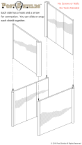
Mounting Clearance
Requirements
TIP Hot air rises. The temperature at the top of the enclosure is often
higher than the temperature in other parts of the enclosure, which is
likely if air is not circulating.
IMPORTANT
The computer can operate at a range of extremes. If you continuously
operate the computer at its highest rated temperature, then the life
span of any electronic device is shortened, which includes the touch
screen and LCD panel.
55 °C (131 °F) max
outside enclosure
70 °C (158 °F) max
inside enclosure
Restricted
Access Location
Non-display ComputerDisplay Computer
70 °C (158 °F) max
inside enclosure
Integrated Display Computers Non-display Computer
Top
Bottom (I/O ports)
Top
Bottom (I/O ports)
Vertical
(0° tilt)
Top
Bottom (I/O ports)
Vertical
(0° tilt)
PCAP Touch Screen Resistive Touch Screen
IMPORTANT Because of self-heating, do not operate the computer in an enclosure by
using the minimum clearances unless adequate ventilation or other
methods are used to lower the temperature within the enclosure.
Allow enough clearance to install or remove peripheral components, such as
internal drives.
The minimum required enclosure size (HxWxD) is 403 x 497 x 154 mm
(15.87 x 19.57 x 6.06 in.).
/