arietta ALS436SS Installation guide
- Category
- Cooker hoods
- Type
- Installation guide

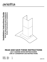
Installation Instructions Guide
Guía de Instrucciones para Instalación
READ AND SAVE THESE INSTRUCTIONS
LEA Y GUARDE ESTAS INSTRUCCIONES
LIB0102593
English page 2
Español página 12

2
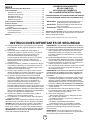
Table of Contents
Important Safety Notice .......................................................... 2
Tools and parts ........................................................................ 3
Location Requirements ...................................................... 3
Product Dimensions ........................................................... 3
Electrical Requirements ..................................................... 4
Venting Requirements ........................................................ 4
Venting Methods ................................................................ 4
Installation Instructions .......................................................... 5
Electrical Connection............................................................... 6
Hood Description...................................................................... 8
Controls...............................................................................8
Range Hood Care...................................................................... 9
Grease lter..........................................................................9
Replacing the light bulb........................................................10
Warranty..................................................................................... 11
APPROVED FOR RESIDENTIAL APPLIANCES
FOR RESIDENTIAL USE ONLY
READ AND SAVE THESE INSTRUCTIONS
PLEASE READ ENTIRE INSTRUCTIONS BEFORE PROCEEDING.
INSTALLATION MUST COMPLY WITH ALL LOCAL CODES.
IMPORTANT: Save these Instructions for the Local Electrical
Inspector’s use.
INSTALLER: Please leave these Instructions with this unit for
the owner.
OWNER: Please retain these instructions for future
reference.
Safety Warning:Turn off power circuit at service panel and lock
out panel before wiring this appliance.
Requirement 120 VAC, 60 Hz. 15 or 20 A Branch Circuit
IMPORTANT SAFETY INSTRUCTIONS
WARNING: TO REDUCE THE RISK OF FIRE, ELECTRIC
SHOCK, OR INJURY TO PERSONS, OBSERVE THE
FOLLOWING:
■ Use this unit only in the manner intended by the
manufacturer. If you have questions, contact the
manufacturer.
■ Before servicing or cleaning the unit, switch power off at
service panel and lock the service disconnecting means to
prevent power from being switched on accidentally. When
the service disconnecting means cannot be locked, securely
fasten a prominent warning device, such as a tag to the
service panel.
■ Installation work and electrical wiring must be done by
qualied person(s) in accordance with all applicable codes
and standards, including re-rated construction.
■ Sufcient air is needed for proper combustion and
exhausting of gases through the ue (chimney) of fuel
burning equipment to prevent backdrafting. Follow the
heating equipment manufacturer’s guideline and safety
standards such as those published by the National Fire
Protection Association (NFPA), the American Society for
Heating, Refrigeration and Air Conditioning Engineers
(ASHRAE), and the local code authorities.
■ When cutting or drilling into wall or ceiling; do not damage
electrical wiring and other hidden utilities.
■ Ducted fans must always be vented outdoors.
CAUTION: For general ventilating use only. Do not use to
exhaust hazardous or explosive materials and vapors.
CAUTION: To reduce risk of re and to properly exhaust air,
be sure to duct air outside - do not vent exhaust air into
spaces within walls or ceilings, attics or into crawl spaces, or
garages.
WARNING: TO REDUCE THE RISK OF FIRE, USE ONLY MET-
AL DUCTWORK
WARNING: TO REDUCE THE RISK OF A RANGE TOP
GREASE FIRE:
■ Never leave surface units unattended at high settings.
Boilovers cause smoking and greasy spillovers that may
ignite. Heat oils slowly on low or medium settings.
■ Always turn hood ON when cooking at high heat or when
ambeing food (i.e. Crepes Suzette, Cherries Jubilee,
Peppercorn Beef Flambé).
■ Clean ventilating fans frequently. Grease should not be
allowed to accumulate on fan or lter.
■ Use proper pan size. Always use cookware appropriate for
the size of the surface element.
WARNING: TO REDUCE THE RISK OF INJURY TO
PERSONS IN THE EVENT OF A RANGE TOP GREASE FIRE,
OBSERVE THE FOLLOWING:
a
■ SMOTHER FLAMES with a close tting lid, cookie sheet, or
metal tray, then turn off the burner. BE CAREFUL TO
PREVENT BURNS. If the ames do not go out
immediately, EVACUATE AND CALL THE FIRE
DEPARTMENT.
■ NEVER PICK UP A FLAMING PAN - you may get burned.
■ DO NOT USE WATER, including wet dishcloths or towels -
a violent steam explosion will result.
■ Use an extinguisher ONLY if:
-You know you have a class ABC extinguisher, and you
already know how to operate it.
– The re is small and contained in the area where it
started.
– The re department is being called.
– You can ght the re with your back to an exit.
a
Based on “Kitchen Fire Safety Tips” published by NFPA.
WARNING: To reduce the risk of re or electrical shock,
do not use this fan with any solid-state speed control device.
READ AND SAVE THESE INSTRUCTIONS

3
†®TORX is a registered trademark of Saturn Fasteners, Inc.
Gather the required tools and parts before starting installation.
Read and follow the instructions provided with any tools listed
here.
CAUTION:
Remove carton carefully, Wear gloves to protect against sharp
edges.
Tools needed (all models)
■ Wire nuts
■ Metal duct lenght to suit installation
■
1
⁄2 ” Romex wire connector
■ 6” rounded metal duct lenght to suit installation
■ Measuring tape
■ Pliers
■ Gloves
■ Knife
■ Safety glasses
■ Electric drill with
5
⁄16” and
3
⁄8” Bits
■ Spirit level
■ Duct tape
■ Screwdrivers:
■ Philips (Posidrive #2)
■ Torx #2
■ Wire cutter/ stripper
■ Masking tape
■ Hammer
■ Saw, jigsaw or reciprocating saw
Parts Supplied
Remove parts from packages. Check that all parts are included.
■ Hood canopy assembly with blower.
■ Lamps already installed.
■ Air transition
■ Grease lter
■ Duct covers
■ Hardware package. Includes:
• Template
• Duct cover support bracket (1 piece)
• Use, care and installation guide
• Wood screws (6 pieces- 5 x 45 mm)
• Concrete wall anchors (6 pieces- 8 x 40 mm)
• Assembly screws (4 pieces - 4.2 x 8 mm)
• Air transition screws (2 pieces - 3.5 x 9.5 mm)
• TORX 10 adapter
• TORX 20 adapter
Optional Accesories
■ Recirculation KIT (KIT01937).
Tools and Parts
Location Requirements
IMPORTANT: Observe all governing codes and ordinances.
Have a qualied technician install the range hood. It is the
installer’s responsibility to comply with installation clearances
specied on the model/serial rating plate. The model/serial rating
plate is located behind the left lter on the rear wall of the vent
hood.
Canopy hood location should be away from strong draft areas,
such as windows, doors and strong heating vents.
Cabinet opening dimensions that are shown must be used. Given
dimensions provide minimum clearance.
Grounded electrical outlet is required. See “Electrical Require-
ments” section.
The canopy hood is factory set for venting through the roof or
wall. For non-vented (recirculating) installation, the KIT01937
must be purchased with your provider.
For Mobile Home Installations
The installation of this range hood must conform to the
Manufactured Home Construction Safety Standards, Title 24
CFR, Part 328 (formerly the Federal Standard for Mobile Home
Construction and Safety, Title 24, HUD, Part 280) or when such
standard is not applicable, the standard for Manufactured Home
Installation 1982 (Manufactured Home Sites, Communities and
Setups) ANSI A225.1/NFPA 501A, or latest edition, or with local
codes.
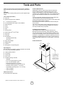
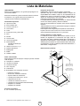
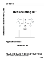
Product Dimensions
6”
(15.24 cm)
10
3
⁄4”
(27.3 cm)
13
3
⁄16”
(33.5 cm)
Ductless (recirculating)
version only
*Max 42
9
⁄16” (108 cm)
*Min 28
4
⁄16” (71.7 cm)
Ducted version only
*Max 38
14
⁄16” (98.76 cm)
*Min 24
9
⁄16” (62.4 cm)
5”
(12.6 cm)
19
11
⁄16”
(50 cm)
30” (76.2 cm)
or
36” (91.4 cm)

4
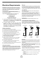
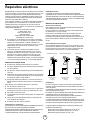
Electrical Requirements
IMPORTANT: The range hood must be electrically grounded in
accordance with local codes and ordinances, or in the absence
of local codes, with the National Electrical Code, ANSI/NFPA 70
(latest edition) or Canadian Electrical Code, CSA C22.1 No.
0-M91 (latest edition).
If codes permit and a separate ground wire is used, it is
recommended that a qualied electrical installer determine that
the ground path is adequate.
A copy of the above code standards can be obtained from:
National Fire Protection Association
1 Batterymarch Park
Quincy, MA 02169-7471
CSA International
8501 East Pleasant Valley Road
Cleveland, Ohio 44131-5575
■ A 120 volt, 60 Hz, AC only, 15- or 20-amp, fused electrical
circuit is required. A time-delay fuse or circuit breaker is also
recommended. It is recommended that a separate circuit
serving only this range hood be provided.
■ To minimize possible shock hazard, the cord must be
plugged into a mating, 3 prong, grounding-type outlet,
grounded in accordance with local codes and ordinances. If a
mating outlet is not available, it is the personal responsibility
and obligation of the customer to have the properly grounded
outlet installed by a qualied electrician.
VENTING REQUIREMENTS
■ Vent system must terminate to the outdoors.
■ Do not terminate the vent system in an attic or other enclosed area.
■ Do not use a 4” (10.2 cm) laundry-type wall caps.
■ Use metal vent only. A rigid metal vent is recommended.
Plastic or metal foil vent is not recommended.
■ The length of the vent system and number of elbows should
be kept to a minimum to provide efcient performance.
For the most efcient and quiet operation:
■ Use no more than three 90° elbows.
■ Make sure there is a minimum of 24” (61.0 cm) of straight
vent between the elbows if more than 1 elbow is used.
■ Do not install 2 elbows together.
■ Use clamps to seal all joints in the vent system and use
furnace duct tape to fully seal joint connection.
■ Use caulking to seal exterior wall or roof opening around the cap.
■ The size of the vent should be uniform.
Cold weather installations
An additional back draft damper should be installed to minimize
backward cold air ow and a thermal break should be installed to
minimize conduction of outside temperatures as part of the vent
system. The damper should be on the cold air side of the thermal break.
The break should be as close as possible to where the vent
system enters the heated portion of the house.
Makeup air
Local building codes may require the use of makeup air systems
when using ventilation systems with greater than specied CFM
of air movement. The specied CFM varies from locale to locale.
Consult your HVAC professional for specic requirements in your area.
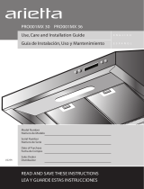
Venting Methods
This canopy range hood is factory set for venting through the
roof or through the wall.
A 6” (15.2 cm) round vent system is needed for installation (not
included). The hood exhaust opening is 6” (15.2 cm) round.
NOTE: Flexible vent is not recommended. Flexible vent creates
back pressure and air turbulence that greatly reduce performance.
Vent system can terminate either through the roof or wall. To vent
through the wall, a 90° elbow is needed.
Rear Discharge
A 90° elbow may be installed immediately above the hood.
For Non-Vented (Recirculating) Installations
If it is not possible to vent cooking fumes and vapors to the
outside, the hood can be used in the non-vented (recirculating)
version, using a Recirculation Kit (which includes charcoal lters
and a deector). To order, see the “Optional Accesories” section.
Exit through the roof Exit through the wall Recirculating
A
B
C
A
B
C
A
B
C
A. Roof cap
B. Duct
C. Transition
A. Wall cap
B. 90° Elbow
C. Transition
A. Air deector
B. Duct
C. Transition
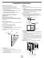
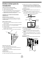
Preparation
Do not cut a joist or stud unless absolutely necessary. If a joist or
stud must be cut, then a supporting frame must be constructed.
Fittings material is provided to secure the hood to most types of
walls/ceilings.
However, a qualied technician must verify suitability of the mate-
rials in accordance with the type of wall/ceiling.
Before making cutouts, make sure there is proper clearance within
the ceiling or wall for exhaust vent.
Hood installation height above cooktop is the users preference.
The lower the hood is above the cooktop, the more efcient the
capturing of cooking odors, grease and smoke.
Set the hood’s mounting height based on the next recommenda-
tions:
■ Minimum distance “X”: 24” (61.0 cm) from electric cooking
surface.
■ Minimum distance “X”: 30” (76.2 cm) from gas cooking
surfaces.
■ Suggested maximum distance “X”: 36” (91.4 cm).

5
Duckwork and wiring locations
■ Determine the exact location of the vent hood.
■ Locate the template packed with the literature.
■ Installation height: 30” electric cooktop/range or 24” to 30”
electric cooktop/range.
■ Use a level to draw a horizontal straight pencil line on the wall,
wich is your desired installation height.
■ Find the centerline of the cooktop. Use a level to draw a
vertical straight pencil line on the wall.
CHECK TO BE SURE THE LINE IS PERFECTLY
PERPENDICULAR.
Mounting the duct cover bracket
The duct cover bracket should be installed against the back wall
and ush with the ceiling. This bracket will hold the duct cover in
place at the top.
Secure the bracket to the wall:
■ Align the marked centerline on the bracket with the centerline
on the wall.
■ Mark 2 screws hole locations in the wall.
■ Drill
5
⁄16” pilot holes in the marked locations.
■ Install wall fastener anchors.
■ Drive wood screws, by hand, into the fastener to allow anchors
to expand. Remove the screws.
■ Secure the bracked to the wall with wood screws and/or
fasteners.
Ceiling ducting
If the duct will vent straight up to the ceiling:
■ Use level to draw a line straight up, from the centerline on the
template to the ceiling.
■ Measure at least 4
3
⁄4” from the back wall to the circle center of
an 6
1
⁄2” hole on the ceiling.
Wall ducting
If ductwork will vent to rear:
■ Use a level to draw a line straight up from the centerline on the
template.
■ Measure at least 23
3
⁄4”(The measure might vary depending on
the elbow used) above the pencil line that indicates the bottom
installation height, to the circle center of an 6
1
⁄2” diameter duct
hole (Hole may be elongated for duct elbow).
House wiring location
■ The junction box is located on the top left side of the hood.
■ Wiring should enter the back wall at least 20” above the
bottom of the instalation height, and within 5
7
⁄8” and 4
7
⁄8” of the
left side of the centerline.
For ceiling vent ducting
Ceiling
4
3
⁄4” circle
center to wall
6
1
⁄2” dia.hole
Circle center at
23
3
⁄4” above the
marked bottom
pencil line
Horizontal straight
pencil line
For wall
vent duct
Install framing for hood support
■ If drywall is present, mark the screw hole locations. Remove
the template.
■ Cut away enough drywall to expose 2 vertical studs at the holes
location indicated by the template.
■ Install two horizontal supports at least 1”x6” between two wall
studs at the bottom and top mounting holes installation location.
■ The horizontal support must be ush with the room side of the
studs. Use cleats behind both sides of the support to secure to
wall studs.
■ Reinstall drywall and renish.
IMPORTANT: Framing must be capable of supporting 100 lbs.
6
1
⁄2 minimum opening
for ductwork
Cleats view
from rear
1˝ x 6˝ minimum
mounting support
Centerline of
installation
space
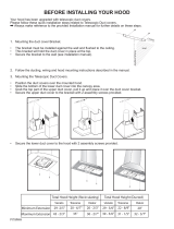
Installation Instructions

6
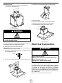
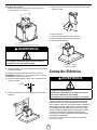
Mounting the hood
1.
Install transition on top of hood (if removed for shipping) with
2 - 3.5 x 9.5 mm sheet metal screws.
A
B
A. Vent transition
B. 3.5 x 9.5 mm screw
WARNING
2 people are required to lift and position the hood
onto the mounting screws.
■ Place the template on the wall along the horizontal line, make sure
the template is leveled and centered with the centerline.
■ Mark “upper” screw holes locations in the wall
IMPORTANT: Check to be sure that hole locations are leveled and
correctly centered bye the vertical centerline.
■ Drive “upper” wood screws by hand. Leave ¼” of distance between
the screw head and the wall.
¼˝
(6.4mm)
■ Remove the grease lter and mount the hood onto the “upper screws”.
■ Mark “lower” wood screw holes locations in wall using a pencil.
■ Remove the hood.
■ Drive the “lower” wood screws, by hand. Remove screws.
■ Mount the hood onto the “upper” wood screws, by hand.
■ Drive and tighten the “lower” wood screws, by hand.
B
A
A
A. 5 x 45 mm screw
B. Mounting slots
Electrical Connection
WARNING
Electrical Shock Hazard
Warning: Turn off the power circuit at the service
panel before wiring this unit.
120 VAC, 15 or 20 Amp circuit required.
ELECTRICAL GROUNDING INSTRUCTIONS
THIS APPLIANCE IS FITTED WITH AN ELECTRICAL JUNCTION
BOX WITH 3 WIRES, ONE OF WHICH (GREEN/YELLOW) SERVES
TO GROUND THE APPLIANCE. TO PROTECT YOU AGAINST
ELECTRIC SHOCK, THE GREEN AND YELLOW WIRE MUST BE
CONNECTED TO THE GROUNDING WIRE IN YOUR HOME ELEC-
TRICAL SYSTEM, AND IT MUST UNDER NO CIRCUMSTANCES BE
CUT OR REMOVED.
Failure to do so can result in death or electrical shock.

7
■ Remove the knockout and the Junction box cover and install
the conduit connector (cULus listed) in junction box.
■ If not already done, install
1
⁄2” conduit connector in j-box.
NOTE: This connector is not included with vent hood.
■ Run black (live), white (neutral), and green (earth) wires (#14 AWG)
according to the National Electrical Code or CSA Standards and local
codes and ordinances in
1
⁄2” conduit from power supply to j-box.
■ Connect black, white, and green wires from power supply to black,
white, and green/yellow wires in j-box respectively.
■ These connections should be done while always making reference to
the electrical diagram found inside the hood.
■ Close j-box cover and reapply.
If range hood does not operate:
■ Check that the circuit breaker is not tripped or the house fuse blown.
■ Disconnect power supply.
■ Check that wiring is correct.
Keep your Installation Instructions and Use and Care Guide close to
range hood for easy reference.
Mounting the duct cover
■ Position the duct cover over the mounted hood.
■ Slide the bottom of the duct into the glass area.
■ Position the top of the duct over the duct mounting bracket. If a
telescopic duct cover is used, grab the upper part of the
telescopic duct cover, pull it and place it in the duct cover
mounting bracket.
■ Secure the top of the duct with 2 assembly screws provided.
■ Secure the bottom of the duct with 2 assembly screws provided.
■ Install the grease lter and turn power on at service panel.
■ Check operation of the hood.

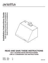
8
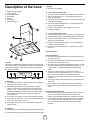
Description of the hood
1. Blower and light controls
2. Lamp housings
3. Grease lter handle
4. Grease lter
5. Canopy
6. Duct covers
7. Recirculating grid
Controls
This hood is equipped with an electronic motor and lamp control.
The control is able to set 3 different fan speeds, turn ON/OFF light
and has a timer function. In the following drawing are described
the main key functions.
12 3
1. Timer Key
■ The default timer setting is 10 minutes, and it can be adjusted
between 20 minutes and 1 minute.
■ After pressing the timer key, the control enters to a timer
setup mode, and user can adjust the timer countdown time
with the “-” and “+” keys within 5 seconds. The timer can be
initiated immediately pressing the timer key, after setting the
timer duration or pressing the timer key twice (default 10
minutes setting).
■ If not action occurs within 5 seconds the countdown will start.
■ During the timer setup the “-” and “+” keys are dedicated to the
timer and no motor action will occur.
■ Once initiated the timer, it can be cancelled by pressing the
timer key again.
2. Light Key
■ Press lamp key to turn ON the light (Lamp state previously OFF).
■ Press lamp key to turn OFF the light (Lamp state previously ON).
3. Display
■ Shows the hood settings.
4. “-” Key. Speed Decrease / OFF
■ This key is used to decrease the fan speed, or turn OFF the fan.
■ The fan will turn OFF if the “-” key is pressed and the hood
was in the rst speed.
■ If the fan is at second speed and the “-” key is pressed, the fan
will be set to rst speed.
■ If the fan is at third speed and the “-” key is pressed, the fan
will be set to second speed.
■ If the fan is OFF and the “-” key is pressed, the control
backlight will light up.
5. “+” Key. Speed Increase / ON
■ This key is used to increase the fan speed, or turn ON the fan.
■ The fan will turn ON if the “+” key is pressed and the hood was OFF.
■ If the fan is at rst speed and the “+” key is pressed, the fan
will be set to second speed.
■ If the fan is at second speed and the “+” key is pressed, the
fan will be set to third speed.
■ If the fan is at third speed and the “+” key is pressed, a beep
will sound.
Special functions
Clock programming
■ The clock can be reprogrammed at any time except during an
active timed function.
■ The clock can be displayed in a twelve hour format and valid
clock times are from 1:00 to 12:59.
■ The clock can be reprogrammed pressing the “Timer” key for 5
seconds, and after, the clock can be adjusted with the “+” and
“-” keys. Colon “:” will ash indicating clock programming
mode.
■ The user can have minute increments / decrements of 1
minute, but if the user keep pressing the “+”/”-” keys for more
than 1 second, the increments / decrements will be of 5
minutes. During this option the control will round to the nearest
5 minutes.
■ The user can nish on reprogramming the clock pressing the
“timer” key.
■ After 1 minute of no key pressed the control will accept the
programmed clock time and will add one minute to the set
clock.
Grease lter saturation alarm
■ After thirty fan functional hours, the display will show “Grease
Filter” if the fan is active. When this icon is shown in the
display, the grease lters installed are required to be washed.
■ To reset the grease lter saturation alarm the user must press
the “+” key for 5 seconds, after this action the icon “grease
lter” is not display, and the hood has the normal display
operation.

9
Charcoal lter saturation alarm (Recirculating accessories)
■ After one hundred and twenty functional hours of the fan, the
display will show “Charcoal Filter” if the fan is active.
■ When this icon ashes on display, the charcoal lters installed
are required to be replaced or reactivated.
■ To reset the grease lter saturation indication the user must
press the “-” key for 5 seconds, after this time the icon
“charcoal lter” is not display and the hood has the normal
display operation.
Audible signal activation and deactivation
■ The audible signals can be activated or deactivated pressing
the “Light” key for 5 seconds.
■ If the audible signal is activated, a tone must sound and the
“Snd” symbol must appear on the display for 2 second.
■ If the audible signal is deactivated, the “Snd” symbol must
appear on the display for 2 second and no sound must sound.
Charcoal lter inclusion and exclusion (Recirculating
accessories)
■ The charcoal lter inclusion or exclusion can be set by
pressing the “-” and “+” keys at the same time for 5 seconds.
■ The Inclusion or exclusion of charcoal lter must be selected
while the lamps and the motor are OFF.
■ When the charcoal has been excluded, the charcoal lter
alarm is disabled.
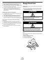
Range Hood Care
The efciency of the range hood system depends on the cleanliness of the
intake and lters.
The frecuency of cleaning depends on the amount and type of cooking.
■ Do not use the ventilating system without the lters in place or with
grease-laden lters or surfaces.
WARNING
To avoid risk of re and explotion do not use
ammable liquids or solvents.
Always unplug or disconnect the appliance from the power supply before
servicing.
WARNING
Be sure the entire hood including the lters and
light bulbs has cooled and grease has solidied
before attempting to clean any part of the appliance.
Filters
The metal grease lters are made of stainless steel anodized aluminum
and are long lasting.
To Remove The Metal Grease Filters
■ Turn the fan and lights off.
■ Pull the spring release handle.

10
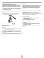
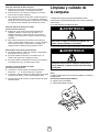
Replacing the halogen lamp
CAUTION: Before replacing the lamps, disconnect power off
to prevent from being switched on accidentally.
Turn off the range hood and allow the halogen / incandescent
lamp to cool. To avoid damage or decreasing the life of the new
bulb, do not touch bulb with bare ngers. Replace bulb, using
tissue or wearing cotton gloves to handle bulb.
If new lamps do not operate, make sure the lamps are inserted
correctly before calling service.
■ Disconnect power.
■ Use a at-blade screwdriver and gently pry the light cover
loose.
■ Remove the lamp and replace with a 120-volt, 40-watt
maximum, halogen lamp made for a G-9 base.
■ Replace the light cover.
■ Reconnect power.
Cleaning
■ Always use the mildest cleaner that will do the job. Use clean,
soft cloths, sponges or paper towels.
■ Rub stainless steel nishes in the direction of the grain. Wipe
area dry to avoid water marks.
■ After cleaning, place all parts in their proper positons before
using.
■ The cleaners recommended below indicate a type and do not
constitute an endorsement. Use all products according to
package directions.
Hood Surface
Stainless Steel Surfaces: Wipe and dry stainless steel in the same
direction as the grain. Avoid using too much pressure, which may
mar the surface. To remove nger prints and give added shine,
use cleaners such as Stainless Steel Magic. Do not allow any
cleaning compounds to remain in contact with stainless steel for
extended periods.
Plastic Surfaces: Wipe with a moist soapy sponge. Rinse and dry.
Aluminum Mesh Filters: Clean lters in the dishwasher or by
agitating in sudsy water. Ensure that there is no soil trapped in the
ne mesh. Dry the lters before reinstalling them.
Optional Recirculating Kit
■ If the model is not vented to the outside, the air will be
recirculated through disposable charcoal lters that help
remove smoke and odors.
■ The charcoal lters cannot be cleaned.
■ They must be replaced.
■ The charcoal lters are clipped inside of each metal grease
lter (mounting instructions included with recirculating kit mod.
KIT01937).
■ The charcoal lters should be replaced every 4-6 months
(depending on hood usage).
NOTE: DO NOT rinse, or put charcoal lters in an automatic
dishwasher.

11
Parts and Service Warranty:
For the period of one year from the date of the original purchase, we will provide free of charge, non consumable parts or components
that failed due to manufacturing defects. During this one year limited warranty, we will also provide, free of charge, all labor and in-home
service to replace the defective part.
What is Not Covered:
■ Damage to the product caused by oods, act of God, re and accidents.
■ Damage caused after delivery.
■ House fuses replacement or resetting of circuit breakers.
■ Service trips to your home to teach you how to use or install the product.
■ Light bulbs, metal, carbon lters and the other consumable parts.
■ The natural wear of nish, and wear due to improper maintenance, use of corrosive and abrasive cleaning
products, pads, and oven cleaner products.
This warranty will be voided when:
■ Product damaged due to improper installation and failure to follow installation instructions, delivery or maintenance.
■ Incidental or consequential damage caused by possible defects with this appliance.
■ Alteration or modication of the Product which may cause in damage to the Product, or failure to operate it
in accordance with specications.
■ Damage because of improper connection with equipment of other manufacturers.
■ Failure of the product if it is negligence, abused, misused, or used for other than the intended purpose or used commercially.
■ Improper repair, modication or servicing of the Product performed by third parties other than Authorized Agents.
Who is Covered:
This warranty is extended to the original purchaser for products purchased for ordinary home use in the 48 mainland states, Hawaii,
Washington D.C. Alaska, Guam, Puerto Rico and the Virgin Islands.
This warranty is non-transferable and applies only to the original purchaser and does not extend to subsequent
owners of this product. This warranty is made expressly in lieu of all other warranties, expressed or implied,
including, but not limited, any implied warranty of merchantability or tness for a particular purpose, and all other
obligations on the part of Elicamex, provided, however, that if the disclaimer of implied warranties is ineffective under applicable law, the
duration of any implied warranties arising by operation of law shall be limited to 1 (one) year from the date of original purchase at retail
or such longer period as may be required by applicable law.
This warranty does not cover any special, incidental and/or consequential damages, nor loss of prots, suffered by
the original purchaser, its customers and/or the users of the Product.
Have your product proof of purchase with date ready for warranty issues.
Or write to:
Elicamex
Av. La Noria #102
Parque Industrial Querétaro KM 28.5
Carretera Querétaro- San Luis Potosí
C.P 76220
México
TO OBTAIN SERVICE UNDER WARRANTY:
or any Service Related Questions, please call:
1-888-732-8018
Staple your receipt here.
Proof of the original purchase
date is needed to obtain service
under the warranty.
TO OBTAIN SERVICE UNDER WARRANTY: You must present proof of original purchase date.
Please keep a copy of your dated proof of purchase (sales slip) in order to obtain service under warranty.
WARRANTY
Page is loading ...
Page is loading ...
Page is loading ...
Page is loading ...
Page is loading ...
Page is loading ...
Page is loading ...
Page is loading ...
Page is loading ...
Page is loading ...
Page is loading ...
Page is loading ...

LIB0102542 Ed. 10 / 14 Printed in Mexico
-
 1
1
-
 2
2
-
 3
3
-
 4
4
-
 5
5
-
 6
6
-
 7
7
-
 8
8
-
 9
9
-
 10
10
-
 11
11
-
 12
12
-
 13
13
-
 14
14
-
 15
15
-
 16
16
-
 17
17
-
 18
18
-
 19
19
-
 20
20
-
 21
21
-
 22
22
-
 23
23
-
 24
24


arietta ALS436SS Installation guide
- Category
- Cooker hoods
- Type
- Installation guide
Ask a question and I''ll find the answer in the document
Finding information in a document is now easier with AI
in other languages
- español: arietta ALS436SS Guía de instalación
Related papers
-
 arietta ADK430SSA Installation guide
-
 arietta Dekor Glass 30 Installation guide
-
 arietta CHN001MX36 Operating instructions
-
 arietta DKW001MX36 Installation guide
-
 arietta DKI001MX36 Installation guide
-
 arietta KIT01938 Installation guide
-
 arietta PRO001MX36 Installation guide
-
 arietta ALZ436SSA Installation guide
-
arietta ADI436SSA Installation guide
-
 arietta DKW001MX36 Installation guide


Other documents
-
ELICA ETB430S1 Install Instructions Toblino
-
-
-
ELICA EPL636S1 Installation guide
-
-
-
-
Electrolux RH36WC60GS User manual
-
-