Page is loading ...

CHN001MX 30 CHN001MX 36
Use, Care and Installation Guide
Guía de Instalación, Uso y Mantenimiento
Model Number
Número de Modelo
Serial Number
Número de Serie
Date of Purchase
Fecha de Compra
Sales Dealer
Distribuidor
READ AND SAVE THESE INSTRUCTIONS
LEA Y GUARDE ESTAS INSTRUCCIONES
LI24HA
E N G L I S H
E S P A Ñ O L

2
English page 2
Spanish page 28
PLEASE READ ENTIRE INSTRUCTIONS BEFORE PROCEEDING.
INSTALLATION MUST COMPLY WITH ALL LOCAL CODES.
INSTALLER: Please leave these Instructions with this unit for the owner.
OWNER: Please retain these instructions for future reference.
Requirement: 120 VAC, 60 Hz. 15 or 20 A Branch Circuit
APPROVED FOR RESIDENTIAL APPLIANCES
FOR RESIDENTIAL USE ONLY

3
Table of Contents
Important Safety Notice ..................................................................5-6
Electrical & Installation Requirements ............................................7
Electrical requirements ...............................................................7
Before installing the hood ...........................................................7
Product Dimensions and Clearances ...............................................8
Installing preparation ..................................................................8
List of Materials ..................................................................................9
Parts included in your hood ........................................................9
Optional accessories .................................................................9
Materials required ......................................................................9
Tools required for installation .....................................................9
Installation Instructions ..............................................................10-18
Ductwork and wiring locations .................................................11
Mounting the duct cover bracket ..............................................12
Option A - Fixed heigh duct cover ............................................12
Option B- Telescopic duct cover ...............................................13
Ceiling ducting ..........................................................................14
Wall ducting ..............................................................................14
House wiring location ...............................................................14
Installing framing for hood support ...........................................15
Mounting the hood....................................................................15
Connecting the ductwork ..........................................................16
Making the electrical connections ............................................16
Mounting duct cover .................................................................18

4
Table of Contents
Use And Care Instructions .........................................................19-22
Control and features .................................................................20
Special Functions .....................................................................21
Clock programming ..................................................................21
Greaseltersaturationalarm ...................................................21
Charcoalltersaturationalarm(Recirculatingaccessories) ...
21
Audible signal activation and deactivation
...............................21
Charcoallterinclusionandexclusion(Recirc.accessories)...21
Heat sensor .............................................................................21
Metalgreaseltermaintenance ..............................................22
Hood maintenance ..................................................................
22
Lamp bulb maintenance ..........................................................22
Available Accessories .................................................................23-25
Charcoallterplacement(Recirculatingaccessories) ............23
Non-returnvalveinstallation(Recirculatingaccessories)........23
Airdeectorinstallation(Recirculatingaccessories) ................24
Telescopic duct cover Kit ..........................................................24
Trouble Shooting ..............................................................................25
List of Parts and Accessories .........................................................26
Warranty ............................................................................................27

5
Important Safety Notice
READ AND SAVE THESE INSTRUCTIONS
CAUTION:
For general ventilating use only. Do Not Use To Exhaust Hazardous or Explosive Materials, And Vapors.
CAUTION:
DURING THE HOOD INSTALLATION, THE PEOPLE INSTALLING THE HOOD MUST WEAR PROTECTION GLOVES
AGAINTS SHARP EDGES.
WARNING
TO REDUCE THE RISK OF FIRE, ELECTRIC SHOCK OR INJURY TO PERSONS, OBSERVE THE FOLLOWING:
• Use this unit only in the manner intended by the manufacturer. If you have questions, contact the
manufacturer.
• Before servicing or cleaning the unit, switch power off at the service panel and lock the service disconnecting
means to prevent power from being switched on accidentally. If the service disconnecting means cannot be
locked, securely fasten a prominent warning device, such as a tag, to the service panel.
• Installationworkandelectricalwiringmustbedonebyqualiedperson(s)inaccordancewithallapplicable
codes & standards, including Fire-rated construction.
• Sufcientairisneededforpropercombustionandexhaustingofgasesthroughtheue(chimney)offuel
burning equipment to prevent back- drafting. Follow the heating equipment manufacturers guideline and safety
standardssuchasthosepublishedbytheNationalFireProtectionAssociation(NFPA),theAmericanSociety
forHeating,RefrigerationandAirConditioningEngineers(ASHRAE),andthelocalcodeauthorities.
• When cutting or drilling into wall or ceiling, do not damage electrical wiring and other hidden utilities.
• Ducted fans must always be vented to the outdoors.
• Do not make alterations to the original wiring.
• Donotattempttorepairorreplaceanypartofyourhoodunlessitisspecicallyrecommendedinthismanual.
Allotherservicingshouldbereferredtoaqualiedtechnician.
• Avoidusingfoodproductsthatproduceamesundertherangehood.
CAUTION:
Toreduceriskofreandtoproperlyexhaustair,besuretoductairoutside-donotventexhaustairintospaceswithin
walls, ceilings, attics, crawl spaces, or garages.
Automatically operated device - to reduce risk of injury disconnect from power supply before servicing.
WARNING
TO REDUCE THE RISK OF FIRE, USE ONLY METAL DUCT WORK.
Installthishoodinaccordancewithallrequirementsspecied.
WARNING
TO REDUCE THE RISK OF FIRE OR ELECTRIC SHOCK, DO NOT USE THIS HOOD WITH ANY EXTERNAL SO-
LIDSTATE SPEED CONTROL DEVICE.

6
Important Safety Notice
WARNING
TO REDUCE THE RISK OF A RANGE TOP GREASE FIRE.
• Never leave surface units unattended at high settings. Boilovers cause smoking and greasy spillovers that may
ignite. Heat oils slowly on low or medium settings.
• AlwaysturnhoodONwhencookingathighheatorwhenambeingfood(i.e.CrepesSuzette,CherriesJubilee,
PeppercornBeefFlambè).
• Cleanventilatingfansfrequently.Greaseshouldnotbeallowedtoaccumulateonfanorlters.
• Useproperpansize.Alwaysusecookwareappropriateforthesizeofthesurfaceelement.
WARNING
TO REDUCE THE RISK OF INJURY TO PERSONS, IN THE EVENT OF A RANGE TOP GREASE FIRE, OBSERVE
THE FOLLOWING “
a
”:
• SMOTHERFLAMESwithaclose-ttinglid,cookiesheet,ormetaltray,thenturnofftheburner.BECAREFUL
TOPREVENTBURNS.Iftheamesdonotgooutimmediately,
EVACUATE AND CALL THE FIRE DEPARTMENT.
• NEVERPICKUPAFLAMINGPAN-youmaybeburned.
• DONOTUSEWATER,includingwetdishclothsortowels-aviolentsteamexplosionwillresult.
• Use an extinguisher ONLY if:
a) YouknowyouhaveaclassABCextinguisher,andyoualreadyknowhowtooperateit.
b) Thereissmallandcontainedintheareawhereitstarted.
c) Theredepartmentisbeingcalled.
d) Youcanghttherewithyourbacktoanexit.
“
a
” Based on "Kitchen Fire Safety Tips" published by NFPA.
Note To Installer
Be sure to leave these instructions to the customer.
Note To The Customer
• Keep this instruction manual for future reference.
• Keep this instruction manual for local inspector.
Operation
Alwaysleavesafetygrillsandltersinplace.Withoutthesecomponents,operatingblowerscouldcatchontohair,ngers
and loose clothing.
The manufacturer declines all responsibility in the event of failure to observe the instructions given here for installation,
maintenance and suitable use of the product. The manufacturer further declines all responsibility for injury due to negligence
and the warranty of the unit automatically expires due to improper maintenance.

7
Electrical & Installation Requirements
ELECTRICAL REQUIREMENTS
IMPORTANT:
• Observe all governing codes and ordinances.
• It is the customer’s responsibility:
o Tocontactaqualiedelectricalinstaller.
o To assure that the electrical installation is adequate and in conformance with National Electrical Code,
ANSI/NFPA70 latest edition* and all local codes and ordinances.
• Ifcodespermitandaseparategroundwireisused,itisrecommendedthataqualiedelectriciandeterminethat
the ground path is adequate.
• Do not ground to a gas pipe.
• Checkwithaqualiedelectricianifyouarenotsurethattherangehoodisproperlygrounded.
• Do not have a fuse in the neutral or ground circuit.
• Save installation instructions for electrical inspector’s use.
• The range hood must be connected with copper wire only.
• Therangehoodshouldbeconnecteddirectlytothefuseddisconnect(orcircuitbreaker)boxthroughmetalelectrical
conduit.
• WiresizesmustconformtotherequirementsoftheNationalElectricalCodeANSI/NFPA70latestedition*and
all local codes and ordinances.
• U.L.(underwrittersLaboratories)listedconduitconnectormustbeprovidedateachendofthepowersupplyconduit
(attherangehoodandatthejunctionbox).
* Copies of the standards listed may be obtained from:
National Fire Protection Association Batterymarch Park Quincy, Massachusetts 02269
Electric requirements
• Theseventhoodsmustbepowersupplied120V,60Hz,andconnectedtoanindividual,properlygroundedbranch
circuit, and protected by 15 or 20 Amps circuit breaker or fuse.
• Wiring must be two wire with ground.
• If the electrical supply does not meet above requirements, call a licensed electrician before proceeding.
• Routehousewiringasclosetotheinstallationlocationaspossible,intheceilingorbackwall.
• The hood must be connected to the house wiring in accordance with the local codes.
CAUTION: This appliance should be properly grounded.
Before installing the hood
• Forthemostefcientairowexhaust,useastraightrunorasfewelbowsaspossible.
CAUTION: Vent unit to outside of building only.
• At least two people are needed for installation.
• Onaverageonetothreehoursarenecessarytocompleteinstallation(withoutconsideringcuttobedoneonwall
and/oroncabinet,installationducts,conduitandelectricalconnectionstothemains).
• Thehoodisttedwithscrewsandwallanchorssuitableformostsurfaces,consultaqualiedinstaller,checkif
theyperfectlytwithyourcabinet/wall.
• Donotuseexducting.
• COLDWEATHERinstallationsshouldhaveanadditionalnonreturnvalve(Accessorynotprovidedwiththehood)
installedtominimizebackwardcoldairowandathermalbreaktominimizeconductionofoutsidetemperatures
as part of the duct work. The damper should be on the cold air side of the thermal break.
• Makeup air local building codes may require the use of makeup air systems when using ducted ventilation systems
greaterthanspeciedCFMofairmovement.ConsultyourHVACprofessionalforspecicrequirementsinyour
area.

8
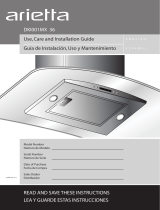
Product Dimensions and Clearances
DuctCoverBracket
16-26/32”
29-5/16”
30” Gas Cooktop
24”-30“ Electric Cooktop
h
h
20”
30“
36“
The vent hood must be installed above the cooking surface at 30" (minimum) if a gas range is used or from 24"
(minimum) to 30" if an electric range is used.
If the customer needs that the duct cover reaches from 8' to 10' ceilings height, then an additional telescopic duct
cover accessory is needed.
The hood may be installed onto a wall and vented to the outdoors, or it can be installed for recirculating operation
(recirculating accessories not supplied with the hood).
This hood must not be installed over any professional cooktop / range.
Installing preparation
Advance planning
• Determine the exact location of the vent hood.
• Plan the route for venting exhaust to the outdoors.
• Use the shortest and straightest duct route possible. For satisfactory performance duct run should not exceed
100’ equivalent length for any duct configurations.
• Refer to “Duct Fittings” chart to compute the maximum permissible length for duct runs to the outdoors.
• Install a wall cap with damper or roof cap at the exterior opening. Order the wall or roof cap and any transition
needed in advance.
• Use 6" round metal ductwork only.
Wall framing for adequate support
• This vent hood is heavy. Adequate structure and support must be provided in all types of installations.
If mounting on dry wall, the hood must be secure to vertical studs in the wall, or to a horizontal support.
• The vent hood should be on site before final framing and wall finishing. This will help to accurately locate the
duct work and electrical service.
• Installation will be easier if the vent hood is installed before the cook-top and countertop are installed.
Removing the packaging
CAUTION: Remove tthe carton carefully. Wear gloves to protect against sharp edges.
WARNING: Remove the protective film covering the product before putting into operation.

9
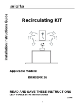
CHECK INSTALLATION HARDWARE
6 wood screws
4 assembly screws
6 concrete wall anchors
Wall mount template
Locate the hardware accesories box packed
with the hood
Pliers
Duct tape
Safety glasses
Masking tape
DUCTLESS CONVERSION KIT
Accesory not included in the hood
TELESCOPIC DUCT COVER KIT
Accesory not included in the hood
Air deflector
Charcoal filter
4 springs
Duct cover support bracket
Duct cover
(dimension show for
reference only)
From 21- 9/32“
To 33 - 3 /32“
13-3/32“
10-19/32“
Measuring tape
Knife
Wire cutter/stripper
Spirit level
Gloves
Strain relief
8?round metal duct,
length to suit installation
Saw, jig saw or
reciprocating saw
Hammer
Screwdrivers:
Phillips (Posidrive) # 2
Torx # 2
Wire nuts
Electric drill with
5/16” and 3/8” Bits
TOOLS REQUIRED FOR INSTALATION
List of
Materials
Parts included in your hood
• Hood structure assembly with blower, transition.
• Lamp already installed.
• 2 Grease filters 30" or 3 Grease filters 36".
• Duct cover.
• Hardware bag with:
o Template
o Duct cover support bracket (1 piece)
o Use, care and installation guide
o Wood screws (6 pieces - 3/16" x 1" 3/4)
o Concrete wall anchors
(6 pieces - 1/8" x 3/8")
o Assembly screws (4 pieces)
Optional accessories
• Telescopic duct cover to fit ceiling height from 8' to 10'
• Re circulation KIT
• Non return valve
Materials required
• Duct tape
• Wire nuts
• Tape to mount template
• 6" rounded metal duct (lenght to suit installation)

10
Installation Instructions
6”
6”
6”
6”
6”
6”
6”
6”
6”
6”

11
Installation Instructions
30” Gas Cooktop (minimum)
24”-30“ Electric Cooktop (min)
h
h
20”
30“
36“
Ductwork and wiring locations
• Determine the exact location of the vent hood.
• Locate the template packed with the literature.
• The height installation is determined by the following image. Mark the location.
• Installationheight:30"(minimum)gascooktop/rangeor24"(minimum)to30"electriccooktop/range.
• Usealeveltodrawahorizontalstraightpencillineonthewall,whichisyourdesiredinstallation
height.
• Find the centerline of the cooktop. Use a level to draw a vertical straight pencil line on the wall.
CHECK TO BE SURE THE LINE IS PERFECTLY PERPENDICULAR.

12
Installation Instructions
• Mark screw holes locations in the wall.
IMPORTANT. Check to be sure that holes locations are leveled, and correctly centered by the vertical
centerline. (This installation instruction applies for concrete wall)
Drill 5/16" pilot holes in the marked locations.
Install wall fastener anchors.
Drivewoodscrews,byhand,intothefastenerstoallowanchorstoexpand.Removescrews.
Secure the bracket to the wall with wood screws and/or fasteners.
Mounting the duct cover bracket
Option A - Fixed height duct cover
• Fromthehorizontallinetracedintheprevioussection,traceahorizontalparallellineasshownbelow.
• Centerthebracketinthetophorizontallineandalignitwiththecenterline,asdescribedinthefollowing
drawing.
28 - 8/16”

13
Installation Instructions
Option B - Telescopic duct cover
Theductbracketshouldbeinstalledagainstthebackwallandushwiththeceiling.Thisbracketwillholdtheduct
cover in place at the top (thisaextraaccessoryavailablenotincludedwiththehood).
.
Secure the bracket to the wall:
• Align the marked centerline on the bracket with the centerline on the wall.
• Mark 2 screw hole locations in the wall.
• Drill 5/16" pilot holes in the marked locations.
• Install wall fastener anchors.
• Drivewoodscrews,byhand,intothefastenertoallowanchorstoexpand.Removethescrews.
• Secure the bracket to the wall with wood screws and/or fasteners.

14
Installation instructions
23
12
/16“
4
12
/16“
30“ Gas Cooktop (minimum)
24“-30“ Electric Cooktop (min)
6
1
/2“
6
1
/2“
Ceiling ducting
If the duct will vent straight up to the ceiling:
• Use level to draw a line straight up, from the centerline on the template to the ceiling.
• Measure at least 4 -12/16 ” from the back wall to the circle center of an 6-½” hole on the ceiling.
Wall ducting
If ductwork will vent to rear:
• Use a level to draw a line straight up from the centerline on the template.
• Measure at least 23 - 12/16" (the measure might vary dependig on the elbow used) above the pencil
line that indicates the bottom installation height, to the circle center of an 6-½” dia. duct hole (Hole may
be elongated for duct elbow).
House wiring location
• The junction box is located on the top left side of the hood.
• Wiring should enter the back wall at least 20" above the bottom of the installation height, and within 5-
7/8" and 4-7/8"of the left side of the centerline.
• Use for the installation 1/2" trade size UL listed metal conduit.

15
Installation Instructions
8-1/2“ min. opening for ductwork
4“x2“ Min. Mounting Support
Install framing for hood support
• If drywall is present, mark the screw hole locations.
Removethetemplate.
• Cut away enough drywall to expose 2 vertical studs at
the holes location indicated by the template.
Installtwohorizontalsupportsatleast 4" X 2"
between two wall studs at the bottom mounting holes
installation location.
• Thehorizontalsupport mustbeushwiththe room
side of the studs.
Use cleats behind both sides of the support to secure
to wall studs.
• Reinstalldrywallandrenish.
IMPORTANT
Framing must be capable of supporting 100 lbs.
WARNING
• When installing to drywall the wall fastener anchors
shall not be used. Disregard the installation steps
referring to wall fastener anchors in the following
instructions.
Mounting the hood (This range hood installation
instruction applies for concrete wall)
WARNING: 2 people are required to lift and position the hood onto the mounting screws.
• Placethetemplateonthewallalongthehorizontalline,makesurethetemplateisleveledandcenteredwith
the centerline.
• Mark“upper”screwholeslocationsinthewall.
• Drill 5/16" pilot holes in the marked locations.
• Install wall fastener anchors.
• IMPORTANT. Check to be sure that hole locations are leveled and correctly centered by the vertical
centerline.
• Drive“upper”woodscrews,byhand.Leave¼“ofdistancebetweenthescrewheadandthewall.
• Mountthehoodontothe“upper”screws.
•Mark“lower”woodscrewholeslocationsinthewallusingapencil.
• Removethehood.
• Drill 5/16" pilot holes in the marked locations.
• Install wall fastener anchors.
• Drive“lower”woodscrews,byhand.Removescrews.
• Mountthehoodontothe“upper”screws.
• Driveandtightthe“upper”woodscrews,byhand.
• Driveandtightthe“lower”woodscrews,byhand.

16
Installation Instructions
Connecting the ductwork
• Installductwork,makingconnectionsinthedirectionofairowasillustrated.
• Push duct over the exhaust outlet.
• Wrapallductjointsandtheangeconnectionswithducttapeforanairtightseal.
• Make the same connection in the wall or ceiling vent exit.
Making the electrical connections
WARNING:
ELECTRICAL SHOCK HAZARD
TURN OFF POWER CIRCUIT AT THE SERVICE PANEL BEFORE WIRING THIS UNIT.
120 V, 15 OR 20 AMP CIRCUIT REQUIRED.
IF HOUSE WIRING IS NOT A 3 WIRE INSTALLATION (NEUTRAL, LINE AND GROUND), A GROUND MUST BE
PROVIDED BY THE INSTALLER. WHEN HOUSE WIRING IS ALUMINUM, BE SURE TO USE U.L. APPROVED
ANTI-OXIDANT COMPOUND AND ALUMINUM-TO-COPPER CONNECTORS.
ELECTRICAL GROUNDING INSTRUCTIONS
THISAPPLIANCEISFITTEDWITHANELECTRICALJUNCTIONBOXWITHTHREEWIRES,THEWIRECOLOR
GREEN/YELLOWSERVESTOGROUNDTHEAPPLIANCE.TOPROTECTYOUAGAINSTELECTRICSHOCK,
THEGREEN/YELLOWWIREMUSTBECONNECTEDTOTHEGROUNDINGWIREINYOURHOMEELECTRICAL
SYSTEM,ANDITMUSTUNDERNOCIRCUMSTANCESBECUTORREMOVED.FAILURETODOSOCANRESULT
INDEATHORELECTRICALSHOCK.
• Removejunctionboxcoverandknockoutonthetopleftside.

17
Installation Instructions
• SecurethemetalelectricalconduittothejunctionboxbytheULapprovedconduittting.
•Electrical connections:
o Toconnectthe“Neutral”,jointbyawirenutthewhitewire(fromtheconduit)tothewhitewirefromthe
junction box.
o Toconnectthe“Line”,jointbyawirenuttheblackwire(fromtheconduit)totheblackwirefromthejunction
box.
o Toconnectthe“Ground”,jointbyawirenuttheGreen/Yellowwire(fromtheconduit)totheGreen/Yellow
wire from the junction box.
• Push wires into junction box.
IMPORTANT: Be sure wires are not pinched
• Secure junction box cover with original screws.

18
Installation Instructions
Mounting the duct cover
• Position the duct cover over the mounted hood.
• Slide the bottom of the duct into the assigned area.
• Position the top of the duct over the duct mounting bracket. If a telescopic duct cover is used, grab the upper
part of the telescopic duct cover, pull it and place it in the duct cover mounting bracket.
• Secure the top of the duct with 2 assembly screws provided.
• Secure the bottom of the duct with 2 assembly screws provided.

19
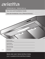
Use And Care Instructions
#ONTROL0ANEL
'REASE&ILTER
#OVER,AMP
)NCANDESCENTLAMPPOSITIONANDNUMBERMAYVARY
$UCT#OVER
$UCT#OVERHOLES
Use and Care Instructions
Before using your hood read this manual carefully. The information on the following pages will help you operate
and maintain your hood properly. Keep it handy to answer your questions.
Ifyoureceiveadamagedhoodcontactimmediatelyyourdealer(builder)thatsoldyouthehood.
To obtain service, see the consumer service pages in the back of this manual. First contact the people who serviced
your appliance, explain why you are not pleased. In most cases, this will solve the problem. If are not pleased, refer
to the warranty page and write all the details including your phone number.

20
Use And Care Instructions
h4)-%2h+%9
hh+%9
h,)'(4h+%9
hh+%9
$)30,!9
#HARCOAL'REASEFILTER
1 2 3
#HARCOAL'REASEFILTER
1 2 3
hh+%9
hh+%9
h4)-%2h+%9
h,)'(4h+%9
$)30,!9
Control and features
This hood is equipped with an electronic motor and lamp control. The control is able to set 3 different fan speeds,
turn ON/OFF light and has a timer function. In the following drawing are described the main key functions.
1. Timer Key
o The default timer setting is 10 minutes, and it can be adjusted between 20 minutes and 1
minute.
o After pressing the timer key, the control enters to a timer setup mode, and user can adjust the
timercountdowntimewiththe“-”and“+”keyswithin5seconds.Thetimercanbeinitiated
immediately pressing the timer key, after setting the timer duration or pressing the timer key
twice(default10minutessetting).
o If not action occurs within 5 seconds the countdown will start.
o Duringthetimersetupthe“-”and“+”keysarededicatedtothetimerandnomotoractionwill
occur.
o Once initiated the timer, it can be cancelled by pressing the timer key again.
2. Light Key
o PresslampkeytoturnONthelight(LampstatepreviouslyOFF).
o PresslampkeytoturnOFFthelight(LampstatepreviouslyON).
3. Display
Shows the hood settings.
4. “-” Key. Speed Decrease / OFF
o This key is used to decrease the fan speed, or turn OFF the fan.
o ThefanwillturnOFFifthe“-”keyispressedandthehoodwasintherstspeed.
o Ifthefanisatsecondspeedandthe“-”keyispressed,thefanwillbesettorstspeed.
o Ifthefanisatthirdspeedandthe“-”keyispressed,thefanwillbesettosecondspeed.
o IfthefanisOFFandthe“-”keyispressed,thecontrolbacklightwilllightup.
5. “+” Key. Speed Increase / ON
o This key is used to increase the fan speed, or turn ON the fan.
o ThefanwillturnONifthe“+”keyispressedandthehoodwasOFF.
o Ifthefanisatrstspeedandthe“+”keyispressed,thefanwillbesettosecondspeed.
o Ifthefanisatsecondspeedandthe“+”keyispressed,thefanwillbesettothirdspeed.
o Ifthefanisatthirdspeedandthe“+”keyispressed,abeepwillsound.
/