Page is loading ...

2
English
Français
Español
Contents
Sommaire
Contenido
page
page
página
2
15
27
English
Contents
Important safety Notice........................................................................................................................................ 3
Electrical & Installation requirements ...............................................................................................................
4
Electrical requirements ................................................................................................................................................................................. 4
Before installing the hood .............................................................................................................................................................................
4
List of Materials.................................................................................................................................................... 5
Parts supplied ............................................................................................................................................................................................... 5
Parts not supplied ......................................................................................................................................................................................... 5
Dimensions and Clearances............................................................................................................................... 5
Duct Options and Examples................................................................................................................................ 6
Installing Preparation...........................................................................................................................................
6
Mounting the duct cover bracket.................................................................................................................................................................... 7
Ceiling / wall ducting .....................................................................................................................................................................................
7
Installation ............................................................................................................................................................8
Mounting the hood ........................................................................................................................................................................................ 8
Electrical Connection................................................................................................................................................................................... 9
Description of the hood & Controls................................................................................................................... 10
Controls.......................................................................................................................................................................................................... 10
Maintenance ......................................................................................................................................................... 11
Available Accesories............................................................................................................................................ 12
Warranty ............................................................................................................................................................... 13
APPROVED FOR RESIDENTIAL APPLIANCES
FOR RESIDENTIAL USE ONLY
READ AND SAVE THESE INSTRUCTIONS
PLEASE READ ENTIRE INSTRUCTIONS BEFORE PROCEEDING.
INSTALLATION MUST COMPLY WITH ALL LOCAL CODES.
IMPORTANT: Save these Instructions for the Local Electrical Inspector’s use.
INSTALLER: Please leave these Instructions with this unit for the owner.
OWNER: Please retain these instructions for future reference.
Safety Warning: Turn off power circuit at service panel and lock out panel, before wiring this appliance.
Requirement: 120 V AC, 60 Hz. 15 or 20 A Branch Circuit

3
READ AND SAVE THESE INSTRUCTIONS
Important safety Notice
CAUTION
FOR GENERAL VENTILATING USE ONLY. DO NOT USE
TO EXHAUST HAZARDOUS OR EXPLOSIVE
MATERIALS OR VAPOURS.
WARNING
TO REDUCE THE RISK OF FIRE, ELECTRIC SHOCK, OR
INJURY TO PERSONS, OBSERVE THE FOLLOWING:
Use this unit only in the manner intended by the
manufacturer. If you have questions, contact the
manufacturer.
Before servicing or cleaning the unit, switch power off
at service panel and lock service panel disconnecting
means to prevent power from being switched on
accidentally. When the service disconnecting means
cannot be locked, securely fasten a prominent warning
device, such as a tag, to the service panel.
Installation Work and Electrical Wiring Must Be Done By
QualiedPerson(s)InAccordanceWithAllApplicable
Codes & Standards, Including Fire-rated Construction.
Sufcientairisneededforpropercombustionand
exhaustingofgasesthroughtheue(Chimney)offuel
burning equipment to prevent back- drafting.
Follow the heating equipment manufacturers guideline
and safety standards such as those published by the
NationalFireProtectionAssociation(NFPA),
theAmericanSocietyforHeating,
RefrigerationandAirConditioningEngineers(ASHRAE),
and the local code authorities.
When cutting or drilling into wall or ceiling, do not
damage electrical wiring and other hidden utilities.
Ducted systems must always be vented to the outdoors.
CAUTION
To reduce risk of re and to properly exhaust air, be
sure to duct air outside - do not vent exhaust air into
spaces within walls, ceilings, attics, crawl spaces, or
garages.
WARNING
TO REDUCE THE RISK OF FIRE, USE ONLY METAL
DUCT WORK.
Install this hood in accordance with all requirements
specied.
WARNING
To Reduce The Risk Of Fire Or Electric Shock, Do Not
Use This Hood With Any External Solid State Speed
Control Device.
WARNING
TO REDUCE THE RISK OF A RANGE TOP GREASE FIRE.
Never leave surface units unattended at high settings.
Boilovers cause smoking and greasy spillovers that may
ignite.Heatoilsslowlyonlowormediumsettings.
AlwaysturnhoodONwhencookingathighheator
whenambeingfood(I.e.CrepesSuzette,Cherries
Jubilee,PeppercornBeefFlambe’).
Clean ventilating fans frequently. Grease should not be
allowedtoaccumulateonfanorlter.
Useproperpansize.Alwaysusecookwareappropriate
forthesizeofthesurfaceelement.
A.
B.
C.
D.
E.
F.
a)
b)
c)
d)
WARNING
TO REDUCE THE RISK OF INJURY TO PERSONS, IN
THE EVENT OF A RANGE TOP GREASE FIRE,
OBSERVE THE FOLLOWING:
a
SMOTHERFLAMESwithaclose-ttinglid,cookie
sheet, or other metal tray, then turn off the gas burner or
theelectricelement.BECAREFULTOPREVENT
BURNS.Iftheamesdonotgooutimmediately,
EVACUATEANDCALLTHEFIREDEPARTMENT.
NEVERPICKUPAFLAMINGPAN-youmaybe
burned.
DONOTUSEWATER,includingwetdishclothsor
towels - a violent steam explosion will result.
Use an extinguisher ONLY if:
YouknowyouhaveaclassABCextinguisher,and
you already know how to operate it.
Thereissmallandcontainedintheareawhereit
started.
Theredepartmentisbeingcalled.
Youcanghttherewithyourbacktoanexit.
a
Basedon“KitchenFireSafetyTips”publishedbyNFPA.
OPERATION
a.Alwaysleavesafetygrillsandltersinplace.Without
these components, operating blowers could catch onto hair,
ngersandlooseclothing.
Themanufacturerdeclinesallresponsibilityintheeventof
failure to observe the instructions given here for installation,
maintenanceandsuitableuseoftheproduct.The
manufacturer further declines all responsibility for injury due
to negligence and the warranty of the unit automatically
expires due to improper maintenance.
a)
b)
c)
d)
1)
2)
3)
4)

4
Electrical & Installation requirements
Electrical requirements
IMPORTANT
Observeallgoverningcodesandordinances.
It is the customer’s responsibility:
Tocontactaqualiedelectricalinstaller.
Toassurethattheelectricalinstallationisadequateandin
conformancewithNationalElectricalCode,ANSI/NFPA70
—latestedition*,orCSAStandardsC22.1-94,Canadian
Electrical Code, Part 1 and C22.2 No.0-M91 - latest
edition** and all local codes and ordinances.
If codes permit and a separate ground wire is used, it is
recommendedthataqualiedelectriciandeterminethatthe
ground path is adequate.
Do not ground to a gas pipe.
Checkwithaqualiedelectricianifyouarenotsurerange
hood is properly grounded.
Do not have a fuse in the neutral or ground circuit.
IMPORTANT
Save Installation Instructions for electrical inspector’s use.
Therangehoodmustbeconnectedwithcopperwireonly.
Therangehoodshouldbeconnecteddirectlytothefused
disconnect(Orcircuitbreaker)boxthroughmetalelectrical
conduit.
WiresizesmustconformtotherequirementsoftheNational
ElectricalCodeANSI/NFPA70—latestedition*,orCSA
Standards C22.1-94, Canadian Electrical Code Part 1 and
C22.2 No. 0-M91 - latest edition** and all local codes and
ordinances.
AU.L.-orC.S.A.-listedconduitconnectormustbeprovided
ateachendofthepowersupplyconduit(attherangehood
andatthejunctionbox).
Copies of the standards listed may be obtained from:
*NationalFireProtectionAssociationBatterymarchParkQuincy,
Massachusetts 02269
**CSAInternational8501EastPleasantValleyRoadCleveland,
Ohio44131-5575
Electric requirements
Theseventhoodsmustbepowersupplied120V,60Hz,
and connected to an individual, properly grounded
branchcircuit,andprotectedby15or20Ampscircuit
breaker or fuse.
Wiring must be two wire with ground.
If the electrical supply does not meet above requirements,
call a licensed electrician before proceeding.
Route house wiring as close to the installation location as
possible, in the ceiling or back wall.
Thehoodmustbeconnectedtothehousewiringin
accordance with the local codes.
CAUTION:Thisapplianceshouldbeproperlygrounded.
Before installing the hood
Forthemostefcientairowexhaust,useastraightrun
or as few elbows as possible.
CAUTION:Ventunittooutsideofbuilding,only.
Atleasttwopeoplearenecessaryforinstallation.
Fittings material is provided to secure the hood to most
typesofwalls/ceilings,consultaQualiedInstaller,
checkiftheyperfectlytwithyourcabinet/wall.
Donotuseexducting.
COLDWEATHERinstallationsshouldhaveanadditional
backdraftdamperinstalledtominimizebackwardcoldair
owandanonmetallicthermalbreaktominimize
conduction of outside temperatures as part of the
ductwork.Thedampershouldbeonthecoldairsideof
the thermal break.
Thebreakshouldbeascloseaspossibletowherethe
ducting enters the heated portion of the house.
Makeupair:Localbuildingcodesmayrequiretheuseof
Make-UpAirSystemswhenusingDuctedVentilation
SystemsgreaterthanspeciedCFMofairmovement.
ThespeciedCFMvariesfromlocaletolocale.Consult
yourHVACprofessionalforspecicrequirementsinyour
area.
•
•
•
•
•
1.
2.
3.
4.
5.
6.

5
List of Materials
Parts supplied
Removing the packaging
CAUTION!
Removing the packaging
CAUTION:Wearglovestoprotectagainstsharpedges.First
remove the carton carefully and take out the duct cover.
CAUTION:Removecarefullytheglasscanopyfromthebox
and put it on a smooth safe surfaces.
Grasp the hood structure from the body and lift straight off the
box.
Remove and properly discard every carton and plastic wrap-
ping content in the package.
Remove parts out of the box, duct covers and other contents.
WARNING!
Removetheprotectivelmcoveringtheproductbefore
putting into operation.
Hoodcanopyassemblywithblower,transition.
2Halogenlamps.
2Greaselters.
Duct cover.
Hardwarebagwith:
Template.
Ductcoversupportbracket(1piece)
Use, care and installation guide
Woodscrews(6pieces-3/16”x1”3/4)
Hoodattachmentanchors
2 - 8x40 anchors
4 - 10x50 anchors
Assemblyscrews
2 - 2.9x6.5 mounting screws
2 - 3.5x9.5 mounting screws
•
•
•
•
•
•
•
•
•
•
•
•
•
•
•
Parts not supplied
Optional Accessories
DuctlessRecirculatingKit
TobeusedonlyintheDuctless(Recirculating)version
includes:2charcoalltersanddeector
ProfessionalStainlessSteelGreaselter
Tools/Materials required
Wire nuts
Tapetomounttemplate
6”roundedmetalductlengthtosuitinstallation
Measuring tape
Pliers
Gloves
Knife
Safety glasses
Electricdrillwith5/16”and3/8”Bits
Strain relief
Spirit level
Duct tape
Screwdrivers:
Phillips(Posidrive)#2
Torx#2
Wire cutter/stripper
Masking tape
Hammer
Saw, jig saw or reciprocating saw
•
•
•
•
•
•
•
•
•
•
•
•
•
•
•
•
•
•
•
•
•
Dimensions and Clearances
*Ductless(Recirculating)versionOnly
**DuctingversionOnly
30” (76.2cm)
36” (91.2 cm
1½”
(4 cm)
20” (50.8 cm)
24
1
/
8
”
(61 cm)
10”
(25.4 cm)
7¼” (18.4 cm
*28
7
/
8
” (73.3 cm) min
*42
1
/
16
” (106.9 cm) max
**28
3
/
8
” (72 cm) min
**38” (96.6 cm) max
6”
8
1
/
8
” (20.7 cm

6
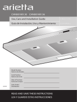
Ducting Options and Examples
Closely follow the instructions set out in this manual.
Allresponsibility,foranyeventualinconveniences,damagesorrescausedbynotcomplyingwiththeinstructionsinthis
manual, is declined.
Venting methods
ThehoodisequippedwithatransitionB for discharge of fumes to the outside (Ducting version).
Should it not be possible to discharge cooking fumes and vapour to the outside, the hood can be used in the Ductless
(Recirculating) version.Attachacharcoallterandthedeector F on the duct cover support bracket G. Fumes and vapours
are recycled through the top grille H by means of a duct connected to the transition Bandthetransitionmountedonthedeec-
tor F.
NOTE: For ductless (Recirculating) version only: purchase the Ductless Recirculating Kit.
Minimum Duct Size (Ducting/Ductless version): 6” Round Pipe.
Preparation
Do not cut a joist or stud unless absolutely necessary. If a joist or stud must be cut, then a supporting frame must be
constructed.
Fittings material is provided to secure the hood to most types of walls/ceilings.
However,aqualiedtechnicianmustverifysuitabilityofthematerialsinaccordancewiththetypeofwall/ceiling.
Before making cutouts, make sure there is proper clearance within the ceiling or wall for exhaust vent.
Hoodinstallationheightabovecooktopistheuserspreference.Thelowerthehoodisabovethecooktop,themoreefcientthe
capturing of cooking odors, grease and smoke.
CAUTION:
FOR 9’ CEILINGS: MOUNT THIS HOOD SO THAT THE BOTTOM EDGE IS AT 30” (76,2 CM) MINIMUM ABOVE THE
COOKING SURFACE.
Check your ceiling height and the hood height maximum before you select your hood.
Flexible ducting:
Ifexiblemetalductingisused,alltheequivalentfeetvaluesinthetableshouldbedoubled.Theexiblemetalductshouldbe
straight and smooth and extended as much as possible.
DONOTuseexibleplasticducting.
NOTE:Anyhomeventilationsystem,suchasaventilationhood,mayinterrupttheproperowofcombustionairandexhaust
requiredbyreplaces,gasfurnaces,gaswaterheatersandothernaturallyventedsystems.
Tominimizethechanceofinterruptionofsuchnaturallyventedsystems,followtheheatingequipmentmanufacturer’sguide
-
linesandsafetystandardssuchasthosepublishedbyNFPAandASHRAE.
ThisHoodMustUsean6”RoundDuct.
•
•
Pipe
Transition(B)
Roof pitch w/
Flashing and cap
Pipe
Transition(B)
Sidewall cap
with gravity
damper
Pipe
Transition(B)
Charcoal
lter
Deector(F)
Topgrille(H)
Supportbracket(G)
VerticalDischarge
Recirculating

7
Mounting the duct cover bracket
Option A - Fixed heigh duct cover
Fromthehorizontallinetracedintheprevioussection,
traceahorizontalparallellineasshownbelow.
Centerthebracketinthetophorizontallineandalignit
with the centerline, as described in the followinG
drawing.
Mark screw holes locations in the wall.
IMPORTANT. Check to be sure that holes locations are
leveled, and correctly centered by the vertical centerline.
Drill5/16”pilotholesinthemarkedlocations.
Install wall fastener anchors.
Drive wood screws, by hand, into the fasteners to allow an-
chors to expand. Remove screws.
Secure the bracket to the wall with wood screws and/or
fasteners.
Option B - Telescopic duct cover
Theductbracketshouldbeinstalledagainstthebackwall
andushwiththeceiling.Thisbracketwillholdthe
ductcoverinplaceatthetop(thisaextraaccessoryavailable
notincludedwiththehood).
Secure the bracket to the wall:
Alignthemarkedcenterlineonthebracketwiththe
centerline on the wall.
Mark 2 screw hole locations in the wall.
Drill5/16”pilotholesinthemarkedlocations.
Install wall fastener anchors.
Drive wood screws, by hand, into the fastener to allow
anchors to expand. Remove the screws.
Secure the bracket to the wall with wood screws and/or
fasteners.
•
•
•
•
•
•
•
•
Ceiling ducting
If the duct will vent straight up to the ceiling:
Use level to draw a line straight up, from the centerline on
the template to the ceiling.
Measureatleast4-12/16”fromthebackwalltothecircle
centerofan6-½”holeontheceiling.
Wall ducting
If ductwork will vent to rear:
Use a level to draw a line straight up from the centerline
on the template.
Measureatleast23-12/16”(themeasuremightvary
dependigontheelbowused)abovethepencillinethat]
indicates the bottom installation height, to the circle center
ofan6-½”diameterducthole(Holemaybeelongatedfor
ductelbow).
House wiring location
Thejunctionboxislocatedonthetopleftsideofthehood.
Wiringshouldenterthebackwallatleast20”abovethe
bottomoftheinstallationheight,andwithin5-7/8”and
4-7/8”oftheleftsideofthecenterline.
•
•
•
•
•
•
Centerline
Bracket line
27
28
/32”
Horizontalstraightpencilmarkedline
Desired installation height
VerticalCenterline
C
e
i
l
i
n
g
Wall
For ceiling vent ducting4
12
/16”circlecenter
to wall
Ceiling
6½”diameterhole
FORWALLVENTDUCT
Circle center at
23
12
/16”abovethe
marked bottom
pencil line
Horizontalstraight
pencil line

8
Install framing for hood support
If drywall is present, mark the screw hole locations.
Remove the template.
Cut away enough drywall to expose 2 vertical studs at
the holes location indicated by the template.
Installtwohorizontalsupportsatleast4X2”between
two wall studs at the bottom and upper mounting holes
installation location.
Thehorizontalsupportmustbeushwiththeroomside
of the studs.
Use cleats behind both sides of the support to secure to
wall studs.
Reinstallldrywallandrenish
IMPORTANT-Framingmustbecapableofsupporting100lbs.
Mounting the hood
WARNING:2peoplearerequiredtoliftandpositionthehood
onto the mounting screws.
Placethetemplateonthewallalongthehorizontalline,
make sure the template is leveled and centered with the
centerline.
Mark“upper”screwholeslocationsinthewall.
IMPORTANT.Checktobesurethatholelocationsare
leveled and correctly centered by the vertical centerline.
Drive“upper”woodscrewsbyhand.Leave¼“of
distance between the screw head and the wall.
Removethegreaselterandmountthehoodontothe
“upper”screws.
•
•
•
•
•
•
•
•
•
•
6-1/2”min.openingforductwork
Viewfromrear
cleats
1”x6”min
Mounting Support
Centerline of
installation
space
Mark“lower”woodscrewholeslocationsinthewallusing
a pencil.
Remove the hood.
Drive“lower”woodscrews,byhand.Removescrews.
Mountthehoodontothe“upper”screws.
Driveandtightenthe“upper”woodscrews,byhand.
Driveandtightenthe“lower”woodscrews,byhand.
Connecting the ductwork
Install ductwork, making connections in the direction of
airowasillustrated.
Push duct over the exhaust outlet.
Wrapallductjointsandtheangeconnectionswithduct
tape for an airtight seal.
Make the same connection in the wall or ceiling vent exit.
•
•
•
•
•
•
•
•
•
•
A.Airow
B. Duct tape over seam
A
B
C

9
Electrical connection
WARNING
Electrical Shock Hazard
Warning: Turn off power circuit at the service panel
before wiring this unit.
120 VAC, 15 or 20 Amp circuit required.
ELECTRICAL GROUNDING INSTRUCTIONS
THISAPPLIANCEISFITTEDWITHANELECTRICAL
JUNCTIONBOXWITH3WIRES,ONEOFWHICH
(GREEN/YELLOW)SERVESTOGROUNDTHE
APPLIANCE.TOPROTECTYOUAGAINST
ELECTRICSHOCK,THEGREENANDYELLOWWIRE
MUSTBECONNECTEDTOTHEGROUNDINGWIRE
INYOURHOMEELECTRICALSYSTEM,ANDIT
MUSTUNDERNOCIRCUNSTANCESBECUTOR
REMOVED.
Failure to do so can result in death or electrical
shock.
Disconnect power.
Remove terminal box cover.
RemovetheknockoutintheterminalboxandinstallaUL
listedorCSAapproved½”strainrelief.
Runhomepowersupplywiringthrough½”strainrelief
into terminal box.
UseULlistedwireconnectorsandconnectwhitewires
(B)together.
UseULlistedwireconnectorsandconnectblackwires
(C)together.
1.
2.
3.
4.
5.
6.
Electrical Shock Hazard
Electrically ground blower.
Connect ground wire to green and yellow ground wire
in terminal box.
Failure to do so can result in death or electrical shock.
Connectgreen(orbare)groundwirefromhomepower
supplytothe2yellow-greengroundwires(D)interminal
boxusingULlistedwireconnectors.
Tightenstrainreliefscrew.
Install terminal box cover.
Reconnect power.
Mounting the duct cover
Position the duct cover over the mounted hood.
Slide the bottom of the duct into the glass area.
Position the top of the duct over the duct mounting
bracket. If a telescopic duct cover is used, grab the
upper part of the telescopic duct cover, pull it and place it
in the duct cover mounting bracket.
Secure the top of the duct with 2 assembly screws
provided.
7.
8.
9.
10.
•
•
•
•
A
B
C
D
E
A.ULlistedwireconnectors
B.White wires
C. Black wires
D.Green(orbare)wireconnectedto
yellow-green wires
E.Homepowersupply

10
Control and features
Thishoodisequippedwithanelectronicmotorandlamp
control.Thecontrolisabletoset3differentfanspeeds,turn
ON/OFFlightandhasatimerfunction.Inthefollowingdraw
-
ing are described the main key functions.
1. Timer Key
Thedefaulttimersettingis10minutes,anditcanbe
adjusted between 20 minutes and 1 minute.
Afterpressingthetimerkey,thecontrolenterstoatimer
setup mode, and user can adjust the timer countdown
timewiththe“-”and“+”keyswithin5seconds.Thetimer
can be initiated immediately pressing the timer key, after
setting the timer duration or pressing the timer key twice
(default10minutessetting).
If not action occurs within 5 seconds the countdown will start.
Duringthetimersetupthe“-”and“+”keysarededicated
to the timer and no motor action will occur.
Onceinitiatedthetimer,itcanbecancelledbypressing
the timer key again.
2. Light Key
PresslampkeytoturnONthelight(LampstatepreviouslyOFF).
PresslampkeytoturnOFFthelight(LampstatepreviouslyON).
3. Display
Shows the hood settings.
4. “-” Key. Speed Decrease / OFF
Thiskeyisusedtodecreasethefanspeed,orturnOFF
the fan.
ThefanwillturnOFFifthe“-”keyispressedandthe
hoodwasintherstspeed.
Ifthefanisatsecondspeedandthe“-”keyispressed,
thefanwillbesettorstspeed.
Ifthefanisatthirdspeedandthe“-”keyispressed,the
fan will be set to second speed.
IfthefanisOFFandthe“-”keyispressed,thecontrol
backlight will light up.
5. “+” Key. Speed Increase / ON
Thiskeyisusedtoincreasethefanspeed,orturn
ONthefan.
ThefanwillturnONifthe“+”keyispressedandthe
hoodwasOFF.
Ifthefanisatrstspeedandthe“+”keyispressed,
the fan will be set to second speed.
Ifthefanisatsecondspeedandthe“+”keyispressed,
the fan will be set to third speed.
Ifthefanisatthirdspeedandthe“+”keyispressed,
a beep will sound.
Special functions
Clock programming
Theclockcanbereprogrammedatanytimeexcept
during an active timed function.
•
•
•
•
•
•
•
•
•
•
•
•
•
•
•
•
•
•
•
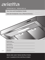
Description of the hood &
Controls
Control panel
Halogenlamps(positionandnumberoflampsmay
vary)
GreaselterreleaseHandle
Grease Filter
Duct cover
Duct cover grid
1.
2.
3.
4.
5.
6.

11
Theclockcanbedisplayedinatwelvehourformatand
valid clock times are from 1:00 to 12:59.
Theclockcanbereprogrammedpressingthe“Timer”
key for 5 seconds, and after, the clock can be adjusted
withthe“+”and“-”keys.Colon“:”willashindicating
clock programming mode.
Theusercanhaveminuteincrements/decrementsof1
minute,butiftheuserkeeppressingthe“+”/”-”keys
for more than 1 second, the increments / decrements will
be of 5 minutes. During this option the control will
round to the nearest 5 minutes.
Theusercannishonreprogrammingtheclockpressing
the“timer”key.
After1minuteofnokeypressedthecontrolwillaccept
the programmed clock time and will add one minute
to the set clock.
Grease lter saturation alarm
Afterthirtyfanfunctionalhours,thedisplaywillshow
“GreaseFilter”ifthefanisactive.Whenthisiconis
showninthedisplay,thegreaseltersinstalledare
required to be washed.
Toresetthegreaseltersaturationalarmtheusermust
pressthe“+”keyfor5seconds,afterthisactionthe
icon“greaselter”isnotdisplay,andthehoodhasthe
normal display operation.
Charcoal lter saturation alarm (Recirculating accessories)
Afteronehundredandtwentyfunctionalhoursofthefan,
thedisplaywillshow“CharcoalFilter”ifthefanisactive.
Whenthisiconashesondisplay,thecharcoallters
installed are required to be replaced or reactivated.
Toresetthegreaseltersaturationindicationtheuser
mustpressthe“-”keyfor5seconds,afterthistime
theicon“charcoallter”isnotdisplayandthehoodhas
the normal display operation.
Audible signal activation and deactivation
Theaudiblesignalscanbeactivatedordeactivated
pressingthe“Light”keyfor5seconds.
If the audible signal is activated, a tone must sound and
the“Snd”symbolmustappearonthedisplayfor2second.
Iftheaudiblesignalisdeactivated,the“Snd”symbolmust
appear on the display for 2 second and no sound must sound.
Charcoal lter inclusion and exclusion
(Recirculating accessories)
Thecharcoallterinclusionorexclusioncanbesetby
pressingthe“-”and“+”keysatthesametimefor5seconds.
TheInclusionorexclusionofcharcoalltermustbe
selectedwhilethelampsandthemotorareOFF.
Whenthecharcoalhasbeenexcluded,thecharcoallter
alarm is disabled.
Heat sensor
Thecontrolisequippedwithaheatsensorthatwillturn
on the blower at second speed if excessive heat
occurs(over70°C)surroundingthecontrolarea.
IftheblowerisOFForifitisoperatingatrstspeed,the
blower will be set automatically to second speed.
During this state, the user may raise the blower speed to
third speed but can not decrease the speed.
When the temperature level on the hood drops to normal,
theblowerwilloperateinthesettingdenedbytheuser
before the alarm occured.
•
•
•
•
•
•
•
•
•
•
•
•
•
•
•
•
•
•
•
Metal grease lter maintenance
Themetalltertrapsgreasereleasedbyfoodsonthecook-
top.Theltermustalwaysbeinstalledwhenthehoodis
operating / used.
To remove:
Pushthelterlock/pivotindirectiontothecenterofthe
lter.
Oncethepivotispushedpulldownthelterslowly.
To replace:
Inserttheltertabsintotheslots
Pushthelterlock/pivotindirectiontothecenterofthe
lter.
Oncethepivotispushed,raisethelterslowlyuntilthe
top and release the pivot.
To clean:
Swishthelterinhotsoapywaterandrinseinclean
water or wash it in the dish washer.
Do not use abrasive cleaners.
Hood maintenance
Clean with a damp, soapy cloth and dry with a clean cloth.
Aglasscleanermayalsobeused.
ATTENTION:Donotwetthecontrolpanel.
Do not use a steel wool pad; it will scratch the surface.
Tocleanthestainlesssteelsurface,usewarmsudsy
water,stainlesssteelcleanerorpolish.Alwayswipe
the surface in the direction of the grain. Follow the cleaner
instructions for cleaning the stainless steel surface.
•
•
•
•
•
•
•
•
•
•

12
Replacing the light bulb
CAUTION: Before replacing the lamps, switch power off
at service panel and lock service panel disconnecting
means to prevent power from being switched on accidentally.
Replacing the Halogen Lamps
Turnoffthehoodinsertandallowthehalogenlamptocool.
Toavoiddamageordecreasingthelifeofthenewbulb,do
nottouchbulbwithbarengers.Replacebulb,usingtissueor
wearing cotton gloves to handle bulb.
If new lamps do not operate, make sure the lamps are in-
serted correctly before calling service.
Disconnect power.
Push up on the lens and turn
it counterclockwise.
Remove the bulb and replace
it with a 120-volt, 50-watt
maximum halogen bulb with a
GU10base.Turnitclockwise
to lock it into place.
Repeat steps 2-3 for the other
bulb if needed.
Reconnect power.
Available Accesories
Charcoal Filter
If the model is not vented to the outside, the air will be recir-
culatedthroughdisposablecharcoalltersthathelpremove
smoke and odors.
Thecharcoallterscannotbecleaned.
Theymustbereplaced.
Cover the grill that protects the suction motor with the carbon
ltersothattheslotsontheltercorrespondtothepinson
the sides of the motor protection grill.
Turnthecarbonlterclockwisetoblockthem(bayonetxing).
Thecharcoalltersshouldbereplacedevery4-6months
(dependingonhoodusage).
NOTE: DO NOTrinse,orputcharcoalltersinanautomatic
dishwasher.
NOTE: Charcoalltersarenotincludedwiththehood.
Theymustbeorderedfromyoursupplier.
Ordertheneededkitspecifyingyourhoodmodelandwidth
size.
1.
2.
3.
4.
5.
Air deector installation (Recirculating version)
Assembletheairdeectorwiththeductcoverbracket
with 2 - assembly screws provided.
A
C
B
B
Measurefromthebottomoftheairdeectortothe
bottom of the hood outlet.
X
A
C
D
B
E
Cuttheducttothemeasuredsize(X).
Removetheairdeector.
Slidetheductontothebottomoftheairdeector.
Placetheassembledairdeectorandductoverthe
exhaust outlet from the hood.
Reassembletheairdeectortotheductcoverbracket
with 2 assembly screws.
Seal connections with vent clamps.
1.
2.
3.
4.
5.
6.
7.
8.
A.Ventcoverbracket
B. 2.9 x 6.5 mm screws
C.Deector
A.Airdeector
B.Ventclamp
C.X=lengthtocutventduct
D.Ventduct
E. Exhaust outlet

13
Warranty
ELICA North America TWO-YEARS LIMITED WARRANTY
TO OBTAIN SERVICE UNDER WARRANTY
Ownermustpresentproofoforiginalpurchasedate.Pleasekeepacopyofyourdatedproofofpurchase(salesslip)inorderto
obtain service under warranty.
PARTS AND SERVICE WARRANTY
Fortheperiodoftwo(2)yearsfromthedateoftheoriginalpurchase,Elicawillprovidefreeofcharge,nonconsumablepartsor
componentsthatfailedduetomanufacturingdefects.Duringthesetwo(2)yearslimitedwarranty,Elicawillalsoprovidefreeof
charge, all labor and in-home service to replace any defective parts.
WHAT IS NOT COVERED
DamageorfailuretotheproductcausedbyaccidentoractofGod,suchas,ood,reorearthquake.
Damageorfailurecausedbymodicationoftheproductoruseofnon-genuineparts.
Damage or failure to the product caused during delivery, handling or installation.
Damage or failure to the product caused by operator abuse.
Damage or failure to the product caused by dwelling fuse replacement or resetting of circuit breakers.
Damage or failure caused by use of product in a commercial application.
Service trips to dwelling to provide use or installation guidance.
Lightbulbs,metalorcarbonltersandanyotherconsumablepart.
Normalwearofnish.
Weartonishduetooperatorabuse,impropermaintenance,useofcorrosiveorabrasivecleaningproducts/padsandoven
cleaner products.
WHO IS COVERED
ThiswarrantyisextendedtotheoriginalpurchaserforproductspurchasedforordinaryresidentialuseinNorthAmerica(Including
theUnitedStates,Guam,PuertoRico,USVirginIslands&Canada).
Thiswarrantyisnon-transferableandappliesonlytotheoriginalpurchaseranddoesnotextendtosubsequentownersof
theproduct.Thiswarrantyismadeexpresslyinlieuofallotherwarranties,expressedorimplied,including,butnotlimitedto
anyimpliedwarrantyofmerchantabilityortnessforaparticularpurposeandallotherobligationsonthepartofElicaNorth
America,provided,however,thatifthedisclaimerofimpliedwarrantiesisineffectiveunderapplicablelaw,thedurationofany
impliedwarrantyarisingbyoperationoflawshallbelimitedtotwo(2)yearsfromthedateoforiginalpurchaseatretailorsuch
longer period as may be required by applicable law.
Thiswarrantydoesnotcoveranyspecial,incidentaland/orconsequentialdamages,norlossofprots,sufferedbytheoriginal
purchaser, its customers and/or the users of the Products.
WHO TO CONTACT
ToobtainServiceunderWarrantyorforanyServiceRelatedQuestion
Please Call:
ElicaNorthAmericaAuthorizedServiceat(888)732-8018
OrbyWritingTo:
ElicaNorthAmerica,AttentionCustomerService,222MerchandiseMartPlaza
Suite947,Chicago,IL60654USA
•
•
•
•
•
•
•
•
•
•
•
•

LI30QA Ed.04/12 Printed in Mexico
/