Page is loading ...

2
English
Français
Español
Contents
Sommaire
Contenido
page
page
página
2
16
30
APPROVED FOR RESIDENTIAL APPLIANCES
FOR RESIDENTIAL USE ONLY
READ AND SAVE THESE INSTRUCTIONS
PLEASE READ ENTIRE INSTRUCTIONS BEFORE PROCEEDING.
INSTALLATION MUST COMPLY WITH ALL LOCAL CODES.
IMPORTANT: Save these Instructions for the Local Electrical Inspector’s use.
INSTALLER: Please leave these Instructions with this unit for the owner.
OWNER: Please retain these instructions for future reference.
Safety Warning: Turn off power circuit at service panel and lock out panel, before wiring this appliance.
Requirement: 120 V AC, 60 Hz. 15 or 20 A Branch Circuit
English
Contents
Important safety Notice......................................................................................................................................... 3
Electrical & Installation requirements ................................................................................................................. 4
Electrical requirements ................................................................................................................................................................................... 4
Before installing the hood ............................................................................................................................................................................... 4
List of Materials...................................................................................................................................................... 5
Parts supplied ................................................................................................................................................................................................. 5
Parts not supplied ........................................................................................................................................................................................... 5
Installation Requirements..................................................................................................................................... 5
Before Installing the hood................................................................................................................................................................................ 5
Product Dimensions & Clearances.................................................................................................................................................................. 5
Installation preparation..................................................................................................................................................................................... 6
Installation Instructions........................................................................................................................................ 7
Ductwork and wiring locations......................................................................................................................................................................... 6
Duct Fittings..................................................................................................................................................................... 7
Ceiling ducting................................................................................................................................................................................................. 8
Wall ducting..................................................................................................................................................................................................... 8
Install framing for hood support....................................................................................................................................................................... 8
Mounting the hood........................................................................................................................................................................................... 9
Connectiing the ductwork................................................................................................................................................................................. 9
Making the electrical connection..................................................................................................................................................................... 9
Mounting the duct cover................................................................................................................................................................................... 10
Use & Care Instructions........................................................................................................................................ 10
Control and features........................................................................................................................................................................................ 11
Special functions.............................................................................................................................................................................................. 11
Metalgreaseltermaintenance.......................................................................................................................................................................12
Hoodmaintenance...........................................................................................................................................................................................12
Lampbulbmaintenance...................................................................................................................................................................................12
Available Accesories............................................................................................................................................. 12
Charcoallterplacement.................................................................................................................................................................................12
Nonreturnvalveinstallation.............................................................................................................................................................................12
Airdeectorinstallation....................................................................................................................................................................................13
Trouble shooting.................................................................................................................................................... 14
WARRANTY............................................................................................................................................................ 15

3
READ AND SAVE THESE INSTRUCTIONS
Important safety Notice
CAUTION
FOR GENERAL VENTILATING USE ONLY. DO NOT USE
TO EXHAUST HAZARDOUS OR EXPLOSIVE
MATERIALS OR VAPOURS.
WARNING
TO REDUCE THE RISK OF FIRE, ELECTRIC SHOCK, OR
INJURY TO PERSONS, OBSERVE THE FOLLOWING:
Use this unit only in the manner intended by the
manufacturer. If you have questions, contact the
manufacturer.
Before servicing or cleaning the unit, switch power off
at service panel and lock service panel disconnecting
means to prevent power from being switched on
accidentally. When the service disconnecting means
cannot be locked, securely fasten a prominent warning
device, such as a tag, to the service panel.
Installation Work and Electrical Wiring Must Be Done By
QualiedPerson(s)InAccordanceWithAllApplicable
Codes & Standards, Including Fire-rated Construction.
Sufcientairisneededforpropercombustionand
exhaustingofgasesthroughtheue(Chimney)offuel
burning equipment to prevent back- drafting.
Follow the heating equipment manufacturers guideline
and safety standards such as those published by the
NationalFireProtectionAssociation(NFPA),
the American Society for Heating,
RefrigerationandAirConditioningEngineers(ASHRAE),
and the local code authorities.
When cutting or drilling into wall or ceiling, do not
damage electrical wiring and other hidden utilities.
Ducted systems must always be vented to the outdoors.
CAUTION
To reduce risk of re and to properly exhaust air, be
sure to duct air outside - do not vent exhaust air into
spaces within walls, ceilings, attics, crawl spaces, or
garages.
WARNING
TO REDUCE THE RISK OF FIRE, USE ONLY METAL
DUCT WORK.
Install this hood in accordance with all requirements
specied.
WARNING
To Reduce The Risk Of Fire Or Electric Shock, Do Not
Use This Hood With Any External Solid State Speed
Control Device.
WARNING
TO REDUCE THE RISK OF A RANGE TOP GREASE FIRE.
Never leave surface units unattended at high settings.
Boilovers cause smoking and greasy spillovers that may
ignite. Heat oils slowly on low or medium settings.
Always turn hood ON when cooking at high heat or
whenambeingfood(I.e.CrepesSuzette,Cherries
Jubilee,PeppercornBeefFlambe’).
Clean ventilating fans frequently. Grease should not be
allowedtoaccumulateonfanorlter.
Useproperpansize.Alwaysusecookwareappropriate
forthesizeofthesurfaceelement.
A.
B.
C.
D.
E.
F.
a)
b)
c)
d)
WARNING
TO REDUCE THE RISK OF INJURY TO PERSONS, IN
THE EVENT OF A RANGE TOP GREASE FIRE,
OBSERVE THE FOLLOWING:
SMOTHERFLAMESwithaclose-ttinglid,cookie
sheet, or other metal tray, then turn off the gas burner or
the electric element. BE CAREFUL TO PREVENT
BURNS.Iftheamesdonotgooutimmediately,
EVACUATE AND CALL THE FIRE DEPARTMENT.
NEVER PICK UP A FLAMING PAN - you may be
burned.
DO NOT USE WATER, including wet dishcloths or
towels - a violent steam explosion will result.
Use an extinguisher ONLY if:
You know you have a class ABC extinguisher, and
you already know how to operate it.
Thereissmallandcontainedintheareawhereit
started.
Theredepartmentisbeingcalled.
Youcanghttherewithyourbacktoanexit.
OPERATION
a.Alwaysleavesafetygrillsandltersinplace.Without
these components, operating blowers could catch onto hair,
ngersandlooseclothing.
The manufacturer declines all responsibility in the event of
failure to observe the instructions given here for installation,
maintenance and suitable use of the product. The
manufacturer further declines all responsibility for injury due
to negligence and the warranty of the unit automatically
expires due to improper maintenance.
a)
b)
c)
d)
1)
2)
3)
4)

4
Electrical & Installation requirements
Electrical requirements
IMPORTANT
Observe all governing codes and ordinances.
It is the customer’s responsibility:
Tocontactaqualiedelectricalinstaller.
To assure that the electrical installation is adequate and in
conformance with National Electrical Code, ANSI/NFPA 70
—latestedition*,orCSAStandardsC22.1-94,Canadian
ElectricalCode,Part1andC22.2No.0-M91-latest
edition** and all local codes and ordinances.
If codes permit and a separate ground wire is used, it is
recommendedthataqualiedelectriciandeterminethatthe
ground path is adequate.
Do not ground to a gas pipe.
Checkwithaqualiedelectricianifyouarenotsurerange
hood is properly grounded.
Do not have a fuse in the neutral or ground circuit.
IMPORTANT
Save Installation Instructions for electrical inspector’s use.
The range hood must be connected with copper wire only.
The range hood should be connected directly to the fused
disconnect(Orcircuitbreaker)boxthroughmetalelectrical
conduit.
WiresizesmustconformtotherequirementsoftheNational
Electrical Code ANSI/NFPA 70 — latest edition*, or CSA
StandardsC22.1-94,CanadianElectricalCodePart1and
C22.2No.0-M91-latestedition**andalllocalcodesand
ordinances.
A U.L.- or C.S.A.-listed conduit connector must be provided
ateachendofthepowersupplyconduit(attherangehood
andatthejunctionbox).
Copies of the standards listed may be obtained from:
* National Fire Protection Association Batterymarch Park Quincy,
Massachusetts02269
** CSA International 8501 East Pleasant Valley Road Cleveland,
Ohio44131-5575
Theseventhoodsmustbepowersupplied120V,60Hz,
and connected to an individual, properly grounded branch
circuit,andprotectedby15or20Ampscircuitbreakeror
fuse.
Wiring must be two wire with ground.
If the electrical supply does not meet above requirements,
call a licensed electrician before proceeding.
Route house wiring as close to the installation location as
possible, in the ceiling or back wall.
The hood must be connected to the house wiring in
accordance with the local codes.
CAUTION: This appliance should be properly grounded.
•
•
•
•
•

5
List of Materials
Parts supplied
Removing the packaging
CAUTION!
Remove carton carefully, Wear gloves to protect against
sharp edges.
WARNING!
Removetheprotectivelmcoveringtheproductbefore
putting into operation.
Hood structure assembly with blower, transition.
Lamp already installed.
2Greaselters30”or3Greaselters36”.
Duct cover.
Hardware bag with:
Template
Ductcoversupportbracket(1piece)
Use, care and installation guide
Woodscrews(6pieces-3/16”x1”3/4)
Concretewallanchors(6pieces-1/8”x3/8”)
Assemblyscrews(4pieces)
•
•
•
•
•
•
•
•
•
•
Parts not supplied
Optional Accessories
Telescopicductcovertotceilingheightfrom8’to10’
Recirculation KIT
Non return valve
Tools/Materials required
Duct tape
Wire nuts
Masking tape
8”roundedmetalduct(lenghttosuitinstallation)
Pliers
Gloves
Knife
Safety glasses
Electricdrillwith5/16”and3/8”Bits
Strain relief
Spirit level
Duct tape
Screwdrivers:
Phillips(Posidrive)#2
Torx#2
Wire cutter/stripper
Hammer
Saw, jig saw or reciprocating saw
•
•
•
•
•
•
•
•
•
•
•
•
•
•
•
•
•
•
•
•
•
Installation Requirements
Before installing the hood
Forthemostefcientairowexhaust,useastraightrun
or as few elbows as possible.
CAUTION: Vent unit to outside of building only.
At least two people are needed for installation.
On average one to three hours are necessary to complete
installation(withoutconsideringcuttobedoneonwall
and/or on cabinet, installation ducts, conduit and electrical
connectionstothemains).
Thehoodisttedwithscrewsandwallanchorssuitable
formostsurfaces,consultaqualiedinstaller,checkif
theyperfectlytwithyourcabinet/wall.
Donotuseexducting.
COLD WEATHER installations should have an additional
nonreturnvalve(Accessorynotprovidedwiththehood)
installedtominimizebackwardcoldairowandathermal
breaktominimizeconductionofoutsidetemperatures
as part of the duct work. The damper should be on the
cold air side of the thermal break.
Makeup air local building codes may require the use of
makeup air systems when using ducted ventilation
systemsgreaterthanspeciedCFMofairmovement.
ConsultyourHVACprofessionalforspecicrequirements
in your area.
•
•
•
•
•
•
•
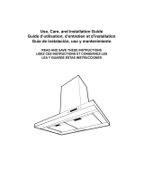
h
20”
30“
36“
17- 4/16”
28- 25/32”
30” Gas Cooktop (minimum)
24”-30“ Electric Cooktop (min)
h
Product Dimensions & Clearances

6
The vent hood must be installed above the cooking surface at
30”(minimum)ifagasrangeisusedorfrom24”(minimum)
to30”ifanelectricrangeisused.
If the customer needs that the duct cover reaches from 8’ to
10’ ceilings height, then an additional telescopic duct
cover accessory is needed.
The hood may be installed onto a wall and vented to the out-
doors, or it can be installed for recirculating operation
(recirculatingaccessoriesnotsuppliedwiththehood).
This hood must not be installed over any professional cooktop
/ range.
Installation preparation
Advance planning
Determine the exact location of the vent hood.
Plan the route for venting exhaust to the outdoors.
Use the shortest and straightest duct route possible. For
satisfactory performance duct run should not exceed
100’equivalentlengthforanyductcongurations.
Referto“DuctFittings”charttocomputethemaximum
permissible length for duct runs to the outdoors.
Install a wall cap with damper or roof cap at the exterior
opening. Order the wall or roof cap and any transition
needed in advance.
Use8”roundmetalductworkonly.
Wall framing for adequate support
This vent hood is heavy. Adequate structure and support
must be provided in all types of installations.
If mounting on dry wall, the hood must be secure to
verticalstudsinthewall,ortoahorizontalsupport.
Theventhoodshouldbeonsitebeforenalframingand
wallnishing.Thiswillhelptoaccuratelylocatethe
duct work and electrical service.
Installation will be easier if the vent hood is installed
before the cook-top and countertop are installed.
Removing the packaging
CAUTION: Remove the carton carefully. Wear gloves to
protect against sharp edges.
WARNING: Removetheprotectivelmcoveringtheproduct
before putting into operation.
•
•
•
•
•
•
•
•
•
•
Installation Instructions
Ductwork and wiring locations
Determine the exact location of the vent hood.
Locate the template packed with the literature.
The height installation is determined by the following
image. Mark the location.
Installationheight:30”(minimum)gascooktop/rangeor
24”(minimum)to30”electriccooktop/range.
Usealeveltodrawahorizontalstraightpencillineonthe
wall, which is your desired installation height.
Find the centerline of the cooktop. Use a level to draw a
vertical straight pencil line on the wall.
CHECK TO BE SURE THE LINE IS PERFECTLY
PERPENDICULAR.
Mounting the duct cover bracket
Option A - Fixed height duct cover
Fromthehorizontallinetracedintheprevioussection,
traceahorizontalparallellineasshownbelow.
Centerthebracketinthetophorizontallineandalignit
with the centerline, as described in the following drawing.
Mark screw holes locations in the wall.
•
•
•
•
•
•
•
•
•
h
20”
30“
36“
30” Gas Cooktop (minimum)
24”-30“ Electric Cooktop (min)
h
Centerline
Bracket line
28”
Horizontalstraightpencilmarkedline
Desired installation height

7
IMPORTANT. Check to be sure that holes locations are
leveled, and correctly centered by the vertical centerline.
(This installation instruction applies for concrete wall).
Drill5/16”pilotholesinthemarkedlocations.
Install wall fastener anchors.
Drive wood screws, by hand, into the fasteners to allow
anchors to expand. Remove screws.
Secure the bracket to the wall with wood screws and/or
fasteners.
Option B - Telescopic duct cover
The duct bracket should be installed against the back wall
andushwiththeceiling.Thisbracketwillholdtheduct
coverinplaceatthetop(thisaextraaccessoryavailable
notincludedwiththehood).
•
•
•
•
•
Ceiling
Vertical centerline
Wall
Duct piece Dimensions Equivalent
Lenght
Quantity
Used
Total
Equivalent
Lenght
Round,
straight
1ft.(perfoot
lenght)
3-1/4”x12”,
3-1/4”x24”
straight
1ft.(perfoot
lenght)
8”round,90°
elbow
15 ft.
8”round,45°
elbow
8 ft.
3-1/4”x12”,
90°elbow
11 ft.
3-1/4”x12”
or45°elbow
6 ft.
3-1/4”x12”,
90°atelbow
24ft.
8”roundto
3-1/4”x12”or
3-1/4”x24”
transition
1 ft.
Duct piece Dimensions Equivalent
Lenght
Quantity
Used
Total
Equivalent
Lenght
3-1/4”x12”
to8”round
transition
8ft.
8”roundto
3-1/4”x12”or
transition90°
elbow
16 ft.
3-1/4”x12”
to8”round
transition90°
elbow
17 ft.
8”round
wall cap with
damper
30ft.
3-1/4”x12”
wall cap with
damper
30ft.
8”roundroof
cap
26ft.
8”roundroof
vent
26ft.
DUCT FITTINGS
Use this chart to compute maximum permissible lengths for
ducts runs to outdoors.
NOTE: Do not exceed maximum permissible equivalents
lengths!
Flexible ducting:
Ifexiblemetalductingisused,alltheequivalentfeetvalues
inthetableshouldbedoubled.Theexiblemetalductshould
be straight and smooth and extended as much as possible.
DO NOT useexibleplasticducting.
NOTE: Any home ventilation system, such as a ventilation
hood,mayinterrupttheproperowofcombustionairandex
-
haustrequiredbyreplaces,gasfurnaces,gaswaterheaters
andothernaturalllyventedsystems.Tominimizethechance
of interruption of such naturally vented systems, follow the
heating equipment manufacturer’s guidelines and safety stan-
dards such as those published by NFPA and ASHERAE.
Thishoodmustusean8”roundduct.
Secure the bracket to the wall:
Align the marked centerline on the bracket with the
centerline on the wall.
Mark2screwholelocationsinthewall.
Drill5/16”pilotholesinthemarkedlocations.
Install wall fastener anchors.
Drive wood screws, by hand, into the fastener to allow
anchors to expand. Remove the screws.
Secure the bracket to the wall with wood screws and/or
fasteners.
•
•
•
•
•
•

8
Install framing for hood support
If drywall is present, mark the screw hole locations.
Remove the template.
Cutawayenoughdrywalltoexpose2verticalstuds
at the holes location indicated by the template.
Installtwohorizontalsupportsatleast4”X2”
between two wall studs at the bottom mounting holes
installation location.
Thehorizontalsupportmustbeushwiththeroom
side of the studs.
Use cleats behind both sides of the support to
secure to wall studs.
Reinstalldrywallandrenish.
IMPORTANT
Framing must be capable of supporting 100 lbs.
WARNING
When installing to drywall the wall fastener anchors
shall not be used. Disregard the installation steps
referring to wall fastener anchors in the following
instructions.
•
•
•
•
•
Ceiling ducting
If the duct will vent straight up to the ceiling:
Use level to draw a line straight up, from the centerline on the template to the ceiling.
Measureatleast4-12/16”fromthebackwalltothecirclecenterofan8-½”holeontheceiling.
Wall ducting
If ductwork will vent to rear:
Use a level to draw a line straight up from the centerline on the template.
Measureatleast23-12/16”(themeasuremightvarydependigontheelbowused)abovethepencilline
thatindicatesthebottominstallationheight,tothecirclecenterofan8-½”diameterducthole(Holemay
beelongatedforductelbow).
House wiring location
The junction box is located on the top left side of the hood.
Wiringshouldenterthebackwallatleast20”abovethebottomoftheinstallationheight,andwithin
5-7/8”and4-7/8”oftheleftsideofthecenterline.
Usefortheinstallation1/2”tradesizeULlistedmetalconduit.
•
•
•
•
•
•
•
8
1
/2“
4
12
/16“(Atleast)
8
1
/2“
23
12
/
16
“
30“GasCooktop(minimum)
24“-30“ElectricCooktop(min)
8-1/2“min.openingforductwork
4“x2“Min.MountingSupport

9
Mounting the hood (This range hood installation
instruction applies for concrete wall)
WARNING: 2peoplearerequiredtoliftandpositionthehood
onto the mounting screws.
Placethetemplateonthewallalongthehorizontalline,
make sure the template is leveled and centered with
the centerline.
Mark“upper”screwholeslocationsinthewall.
Drill5/16”pilotholesinthemarkedlocations.
Install wall fastener anchors.
IMPORTANT. Check to be sure that hole locations are leveled
and correctly centered by the vertical centerline.
Drive“upper”woodscrews,byhand.Leave¼“of
distance between the screw head and the wall.
Mountthehoodontothe“upper”screws.
Mark“lower”woodscrewholeslocationsinthewallusing
a pencil.
Remove the hood.
Drill5/16”pilotholesinthemarkedlocations.
Install wall fastener anchors.
Drive“lower”woodscrews,byhand.Removescrews.
Mountthehoodontothe“upper”screws.
Driveandtightthe“upper”woodscrews,byhand.
Driveandtightthe“lower”woodscrews,byhand.
•
•
•
•
•
•
•
•
•
•
•
•
•
•
Connecting the ductwork
Install ductwork, making connections in the direction of
airowasillustrated.
Push duct over the exhaust outlet.
Wrapallductjointsandtheangeconnectionswithduct
tape for an airtight seal.
Make the same connection in the wall or ceiling vent exit.
Making the electrical connections
WARNING:
ELECTRICAL SHOCK HAZARD
TURN OFF POWER CIRCUIT AT THE SERVICE PANEL
BEFORE WIRING THIS UNIT.
120 V, 15 OR 20 AMP CIRCUIT REQUIRED.
IF HOUSE WIRING IS NOT A 3 WIRE INSTALLATION
(NEUTRAL, LINE AND GROUND), A GROUND MUST BE
PROVIDED BY THE INSTALLER. WHEN HOUSE WIRING
IS ALUMINUM, BE SURE TO USE U.L. APPROVED
ANTI-OXIDANT COMPOUND AND ALUMINUM-TO-
COPPER CONNECTORS.
ELECTRICAL GROUNDING INSTRUCTIONS
THIS APPLIANCE IS FITTED WITH AN ELECTRICAL
JUNCTION BOX WITH THREE WIRES, THE WIRE COLOR
GREEN / YELLOW SERVES TO GROUND THE APPLI-
ANCE. TO PROTECT YOU AGAINST ELECTRIC SHOCK,
THE GREEN/YELLOW WIRE MUST BE CONNECTED TO
THE GROUNDING WIRE IN YOUR HOME ELECTRICAL
SYSTEM, AND IT MUST UNDER NO CIRCUMSTANCES BE
CUT OR REMOVED. FAILURE TO DO SO CAN RESULT
IN DEATH OR ELECTRICAL SHOCK.
Remove junction box cover and knockout on the top left
side.
•
•
•
•
•
Duct tape
over seam
Air Flow Direction
Knockout
Junction Box
Wall Cover

10
Secure the metal electrical conduit to the junction box by
theULconduittting.
Electrical connections:
Toconnectthe“Neutral”,jointbyawirenutthewhite
wire(fromtheconduit)tothewhitewirefromthe
junction box.
Toconnectthe“Line”,jointbyawirenuttheblackwire
(fromtheconduit)totheblackwirefromthejunction
box.
Toconnectthe“Ground”,jointbyawirenuttheGreen
Yellowwire(fromtheconduit)totheGreen/Yellow
wire from the junction box.
Push wires into junction box.
IMPORTANT: Be sure wires are not pinched
Secure junction box cover with original screws.
Mounting the duct cover
Position the duct cover over the mounted hood.
Slide the bottom of the duct into the assigned area.
Position the top of the duct over the duct mounting
bracket. If a telescopic duct cover is used, grab the upper
part of the telescopic duct cover, pull it and place it in the
duct cover mounting bracket.
•
•
•
•
•
•
•
•
•
•
House Wiring
UL listed nuts
Metal Electrical
Conduit
Securethetopoftheductwith2assemblyscrews
provided.
Securethebottomoftheductwith2assemblyscrews
provided.
Use & Care Instructions
Before using your hood read this manual carefully. The infor-
mation on the following pages will help you operate
and maintain your hood properly. Keep it handy to answer
your questions.
If you receive a damaged hood contact immediately your
dealer(builder)thatsoldyouthehood.
To obtain service, see the consumer service pages in the
back of this manual. First contact the people who serviced
your appliance, explain why you are not pleased. In most
cases, this will solve the problem. If are not pleased, refer
to the warranty page and write all the details including your
phone number.
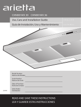
•
•
Control Panel
Grease Filter
Cover Lamp
IncandescentLamp(positionandnumbermayvary)
Duct Cover
Duct Cover hole
1.
2.
3.
4.
5.
6.
1
2 3 - 4
5
6

11
Control and features
This hood is equipped with an electronic motor and lamp
control.Thecontrolisabletoset3differentfanspeeds,turn
ON/OFF light and has a timer function. In the following draw-
ing are described the main key functions.
1. Timer Key
The default timer setting is 10 minutes, and it can be
adjustedbetween20minutesand1minute.
After pressing the timer key, the control enters to a timer
setup mode, and user can adjust the timer countdown
timewiththe“-”and“+”keyswithin5seconds.Thetimer
can be initiated immediately pressing the timer key, after
setting the timer duration or pressing the timer key twice
(default10minutessetting).
If not action occurs within 5 seconds the countdown will start.
Duringthetimersetupthe“-”and“+”keysarededicated
to the timer and no motor action will occur.
Once initiated the timer, it can be cancelled by pressing
the timer key again.
2. Light Key
PresslampkeytoturnONthelight(LampstatepreviouslyOFF).
PresslampkeytoturnOFFthelight(LampstatepreviouslyON).
3. Display
Shows the hood settings.
4. “-” Key. Speed Decrease / OFF
This key is used to decrease the fan speed, or turn OFF
the fan.
ThefanwillturnOFFifthe“-”keyispressedandthe
hoodwasintherstspeed.
Ifthefanisatsecondspeedandthe“-”keyispressed,
thefanwillbesettorstspeed.
Ifthefanisatthirdspeedandthe“-”keyispressed,the
fan will be set to second speed.
IfthefanisOFFandthe“-”keyispressed,thecontrol
backlight will light up.
5. “+” Key. Speed Increase / ON
This key is used to increase the fan speed, or turn
ON the fan.
ThefanwillturnONifthe“+”keyispressedandthe
hood was OFF.
Ifthefanisatrstspeedandthe“+”keyispressed,
the fan will be set to second speed.
Ifthefanisatsecondspeedandthe“+”keyispressed,
the fan will be set to third speed.
Ifthefanisatthirdspeedandthe“+”keyispressed,
a beep will sound.
Special functions
Clock programming
The clock can be reprogrammed at any time except
during an active timed function.
•
•
•
•
•
•
•
•
•
•
•
•
•
•
•
•
•
•
•
1 2 3
The clock can be displayed in a twelve hour format and
validclocktimesarefrom1:00to12:59.
Theclockcanbereprogrammedpressingthe“Timer”
key for 5 seconds, and after, the clock can be adjusted
withthe“+”and“-”keys.Colon“:”willashindicating
clock programming mode.
The user can have minute increments / decrements of 1
minute,butiftheuserkeeppressingthe“+”/”-”keys
for more than 1 second, the increments / decrements will
be of 5 minutes. During this option the control will
round to the nearest 5 minutes.
Theusercannishonreprogrammingtheclockpressing
the“timer”key.
After 1 minute of no key pressed the control will accept
the programmed clock time and will add one minute
to the set clock.
Grease lter saturation alarm
After thirty fan functional hours, the display will show
“GreaseFilter”ifthefanisactive.Whenthisiconis
showninthedisplay,thegreaseltersinstalledare
required to be washed.
Toresetthegreaseltersaturationalarmtheusermust
pressthe“+”keyfor5seconds,afterthisactionthe
icon“greaselter”isnotdisplay,andthehoodhasthe
normal display operation.
Charcoal lter saturation alarm (Recirculating accessories)
After one hundred and twenty functional hours of the fan,
thedisplaywillshow“CharcoalFilter”ifthefanisactive.
Whenthisiconashesondisplay,thecharcoallters
installed are required to be replaced or reactivated.
Toresetthegreaseltersaturationindicationtheuser
mustpressthe“-”keyfor5seconds,afterthistime
theicon“charcoallter”isnotdisplayandthehoodhas
the normal display operation.
Audible signal activation and deactivation
The audible signals can be activated or deactivated
pressingthe“Light”keyfor5seconds.
If the audible signal is activated, a tone must sound and
the“Snd”symbolmustappearonthedisplayfor2second.
Iftheaudiblesignalisdeactivated,the“Snd”symbolmust
appearonthedisplayfor2secondandnosoundmustsound.
Charcoal lter inclusion and exclusion
(Recirculating accessories)
Thecharcoallterinclusionorexclusioncanbesetby
pressingthe“-”and“+”keysatthesametimefor5seconds.
TheInclusionorexclusionofcharcoalltermustbe
selected while the lamps and the motor are OFF.
Whenthecharcoalhasbeenexcluded,thecharcoallter
alarm is disabled.
Heat sensor
The control is equipped with a heat sensor that will turn
on the blower at second speed if excessive heat
occurs(over70°C)surroundingthecontrolarea.
IftheblowerisOFForifitisoperatingatrstspeed,the
blower will be set automatically to second speed.
During this state, the user may raise the blower speed to
third speed but can not decrease the speed.
When the temperature level on the hood drops to normal,
theblowerwilloperateinthesettingdenedbytheuser
before the alarm occured.
•
•
•
•
•
•
•
•
•
•
•
•
•
•
•
•
•
•
•

12
Metal grease lter maintenance
Themetalltertrapsgreasereleasedbyfoodsonthecook-
top.Theltermustalwaysbeinstalledwhenthehoodis
operating / used.
To remove:
Pushthelterlock/pivotindirectiontothecenterofthe
lter.
Oncethepivotispushedpulldownthelterslowly.
To replace:
Inserttheltertabsintotheslots
Pushthelterlock/pivotindirectiontothecenterofthe
lter.
Oncethepivotispushed,raisethelterslowlyuntilthe
top and release the pivot.
To clean:
Swishthelterinhotsoapywaterandrinseinclean
water or wash it in the dish washer.
Do not use abrasive cleaners.
Hood maintenance
Clean with a damp, soapy cloth and dry with a clean cloth.
A glass cleaner may also be used.
ATTENTION: Do not wet the control panel.
Do not use a steel wool pad; it will scratch the surface.
To clean the stainless steel surface, use warm sudsy
water, stainless steel cleaner or polish. Always wipe
the surface in the direction of the grain. Follow the cleaner
instructions for cleaning the stainless steel surface.
Lamp bulb maintenance
UseaPhillips#2screwdrivertoremovethelampcover.
Remove it carefully from its housing.
Removethedamagedlampbulb(turncounterclockwise)
andreplaceitwithanewbulb.E12PhilipsLamp120V,
40W.
•
•
•
•
•
•
•
•
•
•
•
•
Available Accesories
Charcoal lter placement
(Recirculating accessories)
Fitthecharcoalltermattressontheuppersideofeach
greaselter.Useprovidedspringstoxitinplace.
Note: When removing for replacing for a new one do
not remove Fixing Springs, simply pull out one rotating
outwards.
Non-return valve installation
(Recirculating accessories)
Insertend“a”oftherodintothe“plastictransitiontube”,
pushingoutwardsuntilitcrossesthematerial(plastic
transitiontube)withalittleforce.
Placeend“b”oftherodintothe“plastictransitiontube”.
Pushoutwardsuntilitcrossesthematerial(plastic
transitiontube)withalittleforce,therodmustbe
symetrically from both sides.
With the pliers bend both ends of the rod, towards the
“plastictransitiontube”.
•
•
•
Rod
Plastic
Transition
Tube
a
End“a”
End“b”
a
b
a
b
a
b

13
Air deector installation (Recirculating accessories)
Assembletheairdeectorwiththeductcoverbracketwith4assemblyscrewsprovidedasshown.
Measurefromthebottomoftheairdeectortothebottomofthehoodoutlet,asshown.
Cut the duct at the measured size.
Uninstalltheairdeectorremovingthe4assemblyscrews.
Sliptheductontothebottomofthedeector.
Placetheassembleddeectorandductovertheexhaustoutletfromthehood.
Assembletheairdeectorwiththeductcoverbracketwith4assemblyscrewsprovidedasshown.
Telescopic duct cover Kit
FortelescopicductcoverinstallationrefertoInstallationInstructionssection(optionB-telescopicductcoverand
Mountigductcover).
•
•
•
•
•
•
•

14
Potential Effect
Recommended
Action(s) of Failure
Potential Causes Recommended Actions
Lamp does not turn
ON
Electronic Control does not
work. Due to Over Voltage
a)PressinganykeytheLCDlightsupandIconsareinplace?
Yes, Proceed with the following diagnostic sequence
No, Replace the control and user interface.
The lamp was not screwed
correclty
1)Removelampcover.
2)Screwthelampuntilitreachestheendofthesocket.
3)Verify.
Non functional lamp 1)Removethelamp.
2)Verifythelamptobenonfunctionalreviewingthatthelamentis
not burned and be in correct place.
3)Replaceifneeded.
4)Verify
During the hood cleaning, the
motor connector has been loose
and a false contact in the main
harness is performed.
1)Openthecontrolboxremovingthe6screws.
2)Removepowersupplyfromthehood.
3)Verifythattheconnectorcomingfromthemotoriswellconnected
to the connector mounted in the plastic verifying that the locking
system in the connectors is well locked.
4)Iftheconnectorsarenotwellconnected:
- Hold and press main connectors attached in the white plastic.
- Push inwards the motor/lamp connectors until the locking system on
connectors is well attached.
5)Connecthoodtopowersupplyandverify.
FAN does not work Electronic Control does not
work. Due to Over Voltage
a)PressinganykeytheLCDlightsupandIconsareinplace?
Yes, Proceed with the following diagnostic sequence
No, Replace the control and user interface.
During the hood cleaning, the
motor connector has been loose
and a false contact in the main
harness is performed.
1)Openthecontrolboxremovingthe6screws.
2)Removepowersupplyfromthehood.
3)Verifythattheconnectorcomingfromthemotoriswellconnected
to the connector mounted in the plastic and that the locking system in
the connectors is well locked.
4)Iftheconnectorsarenotwellconnected:
- Hold and press main connectors attached in the white plastic.
- Push inwards the motor/lamp connectors until the locking system on
connectors is well attached.
5)Connecthoodtopowersupplyandverify.
The blower is
too noisy
Filters are dirty 1)Verifythatthegreaseand/orcharcoalltersareclean.
2)Iftheyarenotcleanchangecharcoallter,orwash
greaselterandverify.
False contact in the
connectors
During the hood cleaning, the
motor connector has been loose
and a false contact in the main
harness is performed.
1)Openthecontrolboxremovingthe6screws.
2)Removepowersupplyfromthehood.
3)Verifythattheconnectorcomingfromthemotoriswellconnected
to the connector mounted in the plastic and that the locking system in
the connectors is well locked.
4)Iftheconnectorsarenotwellconnected:
- Hold and press main connectors attached in the white plastic.
- Push inwards the motor/lamp connectors until the locking system on
connectors is well attached.
5)Connecthoodtopowersupplyandverify.
The hood and or
the lamp does not
work
A terminal or connector is loose
1)Openthecontrolboxremovingthe6screws.
2)Removepowersupplyfromthehood.
3)Verifythattheconnectorcomingfromthemotoriswellconnected
to the connector mounted in the plastic and that the locking system in
the connectors is well locked.
4)Iftheconnectorsarenotwellconnected:
- Hold and press main connectors attached in the white plastic.
- Push inwards the motor/lamp connectors until the locking system on
connectors is well attached.
5)Connecthoodtopowersupplyandverify.
Trouble shooting

15
Warranty
ELICA North America TWO-YEARS LIMITED WARRANTY
TO OBTAIN SERVICE UNDER WARRANTY
Ownermustpresentproofoforiginalpurchasedate.Pleasekeepacopyofyourdatedproofofpurchase(salesslip)inorderto
obtain service under warranty.
PARTS AND SERVICE WARRANTY
Fortheperiodoftwo(2)yearsfromthedateoftheoriginalpurchase,Elicawillprovidefreeofcharge,nonconsumablepartsor
componentsthatfailedduetomanufacturingdefects.Duringthesetwo(2)yearslimitedwarranty,Elicawillalsoprovidefreeof
charge, all labor and in-home service to replace any defective parts.
WHAT IS NOT COVERED
DamageorfailuretotheproductcausedbyaccidentoractofGod,suchas,ood,reorearthquake.
Damageorfailurecausedbymodicationoftheproductoruseofnon-genuineparts.
Damage or failure to the product caused during delivery, handling or installation.
Damage or failure to the product caused by operator abuse.
Damage or failure to the product caused by dwelling fuse replacement or resetting of circuit breakers.
Damage or failure caused by use of product in a commercial application.
Service trips to dwelling to provide use or installation guidance.
Lightbulbs,metalorcarbonltersandanyotherconsumablepart.
Normalwearofnish.
Weartonishduetooperatorabuse,impropermaintenance,useofcorrosiveorabrasivecleaningproducts/padsandoven
cleaner products.
WHO IS COVERED
ThiswarrantyisextendedtotheoriginalpurchaserforproductspurchasedforordinaryresidentialuseinNorthAmerica(Including
theUnitedStates,Guam,PuertoRico,USVirginIslands&Canada).
This warranty is non-transferable and applies only to the original purchaser and does not extend to subsequent owners of
the product. This warranty is made expressly in lieu of all other warranties, expressed or implied, including, but not limited to
anyimpliedwarrantyofmerchantabilityortnessforaparticularpurposeandallotherobligationsonthepartofElicaNorth
America, provided, however, that if the disclaimer of implied warranties is ineffective under applicable law, the duration of any
impliedwarrantyarisingbyoperationoflawshallbelimitedtotwo(2)yearsfromthedateoforiginalpurchaseatretailorsuch
longer period as may be required by applicable law.
Thiswarrantydoesnotcoveranyspecial,incidentaland/orconsequentialdamages,norlossofprots,sufferedbytheoriginal
purchaser, its customers and/or the users of the Products.
WHO TO CONTACT
To obtain Service under Warranty or for any Service Related Question
Please Call:
ElicaNorthAmericaAuthorizedServiceat(888)732-8018
Or by Writing To:
ElicaNorthAmerica,AttentionCustomerService,222MerchandiseMartPlaza
Suite 947, Chicago, IL 60654 USA
•
•
•
•
•
•
•
•
•
•
•
•

23
Installation de la hotte (s’applique à mur de béton)
AVERTISSEMENT: Utiliser deux ou plus de personnes pour
déplacer et installer la hotte de la cuisinière.
Placerlegabaritsurlemurlelongdelalignehorizontale,
s’assurer que le gabarit est à niveau et centré sur la ligne
de centre.
Indiquerlesemplacementsdesvis“supérieures”dansle
mur.
Percezdes5/16”trousdanslesendroitsmarqués
Installezdesancresdexationmurale.
IMPORTANT:Vérierquetouslesemplacementsdestrous
sont à niveau et correctement centrés sur la ligne de centre
verticale.
Visserlesvisenbois“supérieures”àlamain.
Laisserunedistancede¼“entrelatêtedelavisetle
mur.
Placerlahottesurlesvis“supérieures”.
Indiquerlesemplacementsdesvisàbois“inférieures”sur
le mur en utilisant un crayon.
Enlever la hotte.
Percezdes5/16”trousdanslesendroitsmarqués
Installezdesancresdexationmurale.
Visserlesvisenbois“inférieures”àlamain.Enleverles
vis.
Placerlahottedanslesvis“supérieures”.
Visseretserrerlesvisàbois“supérieures”àlamain.
Visseretserrerlesvisàbois“inférieures”àlamain.
•
•
•
•
•
•
•
•
•
•
•
•
•
•
Raccorder le conduit
Installer le conduit, effectuer les raccords dans la
directionduuxd’aircommeillustré.
Pousser le conduit dans la sortie d’évacuation.
Recouvrir tous les joints des conduits et les raccords à la
bride avec de la toile isolante pour une fermeture hermétique.
Effectuer la même opération pour le raccordement
à l’évacuation dans le mur ou dans le plafond.
Effectuer les connexions électriques
AVERTISSEMENT:
DANGER DE CHOC ÉLECTRIQUE
AVERTISSEMENT: COUPER L’ALIMENTATION À LA
BOÎTE À FUSIBLE AVANT DE RACCORDER CETTE
UNITÉ.
CIRCUIT DE 120 V AC, 15 OU 20 AMP REQUIS.
SI LE CÂBLAGE DES MAISON N’EST PAS UNE
INSTALLATION 3 FILS (NEUTRE, LIGNE ET LA TERRE),
UN SOL DOIT ÊTRE FOURNI PAR L’INSTALLATEUR.
LORS DU CÂBLAGE DES MAISON EST EN ALUMINIUM,
VEILLEZ À UTILISER UL APPROUVÉ COMPOSÉ ANTI-
OXYDANT ET ALUMINIUM-À-CUIVRE CONNECTEURS.
INSTRUCTIONS RACCORDEMENT ELECTRIQUE
A LA TERRE
CET APPAREIL FONCTIONNE AVEC UNE BOITE DE
CONNEXION A TROIS FILS, LE FIL DE LA COULEUR
VERT / JAUNE SERT POUR RACCORDER L’APPAREIL A
LA TERRE. POUR VOUS PROTEGER D’UN EVENTUEL
CHOC ELECTRIQUE, LE FIL JAUNE ET VERT DOIT
ETRE RELIE AU FIL DE LA TERRE DANS VOTRE
CIRCUIT ELECTRIQUE, ET NE DOIT ETRE COUPE
OU ENLEVE SOUS AUCUN PRETEXTE.
NE PAS SUIVRE CES INSTRUCTIONS PEUT RÉSULTER
EN UN CHOC ÉLECTRIQUE ET EN LA MORT.
Enlever le couvercle de la boîte de connexion du
côté supérieur gauche.
•
•
•
•
•
Toile isolante
sur le raccorde
Flux d’air
Knockout
Couvercle boîte
de connexion

LI30NA Ed.10/11 Printed in Mexico
/