11
ThefanwillturnONifthe“+”buttonispressedandthe
hoodwasOFF.
Ifthefanisatrstspeedandthe“+”buttonispressed,
the fan will be set to second speed.
Ifthefanisatsecondspeedandthe“+”buttonispressed,
the fan will be set to third speed.
Ifthefanisatthirdspeedandthe“+”buttonispressed,
the fan will be set to fourth speed.
Ifthefanisatfourthspeedandthe“+”buttonispressed,
a beep will sound.
Clock programming
The clock can be reprogrammed at any time except during
an active timed function.
The clock can be displayed in a twelve hour format and
valid clock times are from 1:00 to 12:59.
Theclockcanbereprogrammedpressingthe“Timer”
button for 3 seconds, and after, the clock can be adjusted
withthe“+”and“-”buttons.
The user can have minute increments / decrements of 1
minute,butiftheuserkeeppressingthe“+”/”-”buttons
for more than 1 second, the increments / decrements will
be of 5 minutes.
During this option the control will round to the nearest 5
minutes.
Theusercannishonreprogrammingtheclockpressing
the“Timer”button.
After 1 minute of no button pressed the control will accept the
programmed clock time and will add one minute to the set clock.
Grease lter saturation alarm (Optional)
After thirty fan functional hours, the display will show
“GreaseFilter”ifthefanisactive.
Whenthisiconisshowninthedisplay,thegreaselters
installed are required to be washed.
Toresetthegreaseltersaturationalarmtheusermust
pressthe“+”buttonfor5seconds,afterthisactionthe
icon“Greaselter”isnotdisplayed,andthehoodhasthe
normal display operation.
Charcoal lter saturation alarm (Optional)
After one hundred and twenty functional hours of the fan,
thedisplaywillshow“CharcoalFilter”ifthefanisactive.
Whenthisiconashesondisplay,thecharcoallters
installed are required to be replaced or reactivated.
Toresetthecharcoalltersaturationindicationtheuser
mustpressthe“-”buttonfor5seconds,afterthistimethe
icon“Charcoallter”isnotdisplayedandthehoodhas
the normal display operation.
Audible signal activation and deactivation
The audible signals can be activated or deactivated
pressingthe“Light”buttonfor5seconds.
If the audible signal is activated, a tone must sound and
the“Snd”symbolmustappearonthedisplayfor3seconds.
Iftheaudiblesignalisdeactivated,the“Snd”symbolmust
appear on the display for 3 seconds and no tone must
sound.
Charcoal lter inclusion and exclusion (Recirculating
accessories)
Thecharcoallterinclusionorexclusioncanbesetby
pressingthe“+”and“-”buttonsatthesametimefor5
seconds.
TheInclusionorexclusionofcharcoalltermustbe
selectedwhilethelampsandthemotorareOFF.
Whenthecharcoallterhasbeenexcluded,thecharcoal
lteralarmisdisabled.
•
•
•
•
•
•
•
•
•
•
•
•
•
•
•
•
•
•
•
•
•
•
Heat sensor
The control is equipped with a heat sensor that will turn
on the blower at third speed if excessive heat occurs
(over149°For65°C)surroundingthecontrolarea.
IftheblowerisOFForifitisoperatingatrstspeed,the
blower will be set automatically to third speed, the display
showstheword“CArE”toindicatethatheatsensorhas
detected an excessive heat.
During this state, the user may raise the blower speed to
fourth speed but can not decrease the speed.
When the temperature level on the hood drops to normal,
theblowerwilloperateinthesettingdenedbytheuser
before the alarm occured.
Maintenance
ATTENTION! Before performing any maintenance opera-
tion, isolate the hood from the electrical supply by switching
off at the connector and removing the connector fuse.
Or if the appliance has been connected through a plug and
socket, then the plug must be removed from the socket.
Cleaning
Do not spray cleaners directly to the control while cleaning the
Hood.Thecookerhoodshouldbecleanedregularly(atleast
with the same frequency with which you carry out maintenance
ofthefatlters)internallyandexternally.Cleanusingthecloth
dampened with neutral liquid detergent. Do not use abrasive
products. DO NOT USE ALCOHOL!
WARNING:
Failuretocarryoutthebasiccleaningrecommendationsof
thecookerhoodandreplacementoftheltersmaycausererisks.
Therefore, we recommend observing these instructions.
The manufacturer declines all responsibility for any damage
tothemotororanyredamagelinkedtoinappropriate
maintenance or failure to observe the above safety
recommendations.
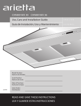
Grease Filter
Traps cooking grease particles.
Theltersshouldbewashedfrequentlyusingnonaggressive
detergents, either by hand or in the dishwasher, which must be
set to a low temperature and a short cycle.
Whenwashedinadishwasher,thegreaseltermaydiscolour
slightly,butthisdoesnotaffectitslteringcapacity.
Toremovethegreaselter,pullthespringreleasehandle.
•
•
•
•