Page is loading ...

DKI001MX 36
Use, Care and Installation Guide
Guía de Instalación, Uso y Mantenimiento
Model Number
Número de Modelo
Serial Number
Número de Serie
Date of Purchase
Fecha de Compra
Sales Dealer
Distribuidor
READ AND SAVE THESE INSTRUCTIONS
LEA Y GUARDE ESTAS INSTRUCCIONES
LI24KC ed.11/11
E N G L I S H
E S P A Ñ O L

2
APPROVED FOR RESIDENTIAL APPLIANCES
FOR RESIDENTIAL USE ONLY
English page 2
Spanish page 28
PLEASE READ ENTIRE INSTRUCTIONS BEFORE PROCEEDING.
INSTALLATION MUST COMPLY WITH ALL LOCAL CODES.
INSTALLER: Please leave these Instructions with this unit for the owner.
OWNER: Please retain these instructions for future reference.
Requirement: 120 VAC, 60 Hz. 15 or 20 A Branch Circuit

3
Table of Contents
Important Safety Notice ..................................................................5-6
Electrical & Installation Requirements ............................................7
Electrical requirements ...............................................................7
Before installing the hood ...........................................................7
List of Materials ..................................................................................8
Parts included in your hood ........................................................8
Optional accessories .................................................................8
Materials required ......................................................................8
Tools required for installation .....................................................8
Installation Instructions ................................................................9-16
Duct ttings...............................................................................10
Product dimensions and clearances ....................................... 11
Ductwork and wiring locations .................................................11
Removing the packaging .........................................................11
Installing preparation ................................................................11
Ceiling Support Structures .......................................................12
Graphic Installation Instructions ...............................................13
Ceiling ducting ..........................................................................14
Conecting the ductwork ............................................................14
Making the electrical connections .......................................15-16

4
Table of Contents
Use And Care Instructions .........................................................17-22
Control and features .................................................................18
Special Functions .....................................................................19
Clock programming ..................................................................19
Grease lter saturation alarm ...................................................19
Charcoal lter saturation alarm (Recirculating accessories) ...20
Audible signal activation and deactivation ...............................20
Charcoal lter inclusion and exclusion (Recirc.accessories) ...20
Heat sensor .............................................................................20
Metal grease lter maintenance ..............................................21
Hood maintenance ..................................................................22
Change lamp bulbs .................................................................22
Available Accessories .................................................................23-24
Charcoal lter placement (Recirculating accessories) ............23
Non-return valve installation (Recirculating accessories) ........23
Air deector installation (Recirculating accessories) ................24
Trouble Shooting ..............................................................................25
List of Parts and Accessories .........................................................26
Warranty ............................................................................................27

5
Important Safety Notice
READ AND SAVE THESE INSTRUCTIONS
CAUTION:
For general ventilating use only. Do Not Use To Exhaust Hazardous or Explosive Materials, And Vapors.
CAUTION:
DURING THE HOOD INSTALLATION, THE PEOPLE INSTALLING THE HOOD MUST WEAR PROTECTION GLOVES
AGAINTS SHARP EDGES.
WARNING
TO REDUCE THE RISK OF FIRE, ELECTRIC SHOCK OR INJURY TO PERSONS, OBSERVE THE FOLLOWING:
• Use this unit only in the manner intended by the manufacturer. If you have questions, contact the
manufacturer.
• Before servicing or cleaning the unit, switch power off at the service panel and lock the service disconnecting
means to prevent power from being switched on accidentally. If the service disconnecting means cannot be
locked, securely fasten a prominent warning device, such as a tag, to the service panel.
• Installation work and electrical wiring must be done by qualied person(s) in accordance with all applicable
codes & standards, including Fire-rated construction.
•
Sufcient air is needed for proper combustion and exhausting of gases through the ue (chimney) of fuel
burning equipment to prevent back- drafting. Follow the heating equipment manufacturers guideline and safety
standards such as those published by the National Fire Protection Association (NFPA), the American Society
for Heating, Refrigeration and Air Conditioning Engineers (ASHRAE), and the local code authorities.
• When cutting or drilling into wall or ceiling, do not damage electrical wiring and other hidden utilities.
• Ducted fans must always be vented to the outdoors.
• Do not make alterations to the original wiring.
• Do not attempt to repair or replace any part of your hood unless it is specically recommended in this manual.
All other servicing should be referred to a qualied technician.
• Avoid using food products that produce ames under the range hood.
CAUTION:
To reduce risk of re and to properly exhaust air, be sure to duct air outside - do not vent exhaust air into spaces within
walls, ceilings, attics, crawl spaces, or garages.
Automatically operated device - to reduce risk of injury disconnect from power supply before servicing.
WARNING
TO REDUCE THE RISK OF FIRE, USE ONLY METAL DUCT WORK.
Install this hood in accordance with all requirements specied.
WARNING
TO REDUCE THE RISK OF FIRE OR ELECTRIC SHOCK, DO NOT USE THIS HOOD WITH ANY EXTERNAL SO-
LIDSTATE SPEED CONTROL DEVICE.

6
Important Safety Notice
WARNING
TO REDUCE THE RISK OF A RANGE TOP GREASE FIRE.
• Never leave surface units unattended at high settings. Boilovers cause smoking and greasy spillovers that may
ignite. Heat oils slowly on low or medium settings.
• Always turn hood ON when cooking at high heat or when ambeing food (i.e. Crepes Suzette, Cherries Jubilee,
Peppercorn Beef Flambè).
• Clean ventilating fans frequently. Grease should not be allowed to accumulate on fan or lters.
• Use proper pan size. Always use cookware appropriate for the size of the surface element.
WARNING
TO REDUCE THE RISK OF INJURY TO PERSONS, IN THE EVENT OF A RANGE TOP GREASE FIRE, OBSERVE
THE FOLLOWING “
a
”:
• SMOTHER FLAMES with a close-tting lid, cookie sheet, or metal tray, then turn off the burner. BE CAREFUL
TO PREVENT BURNS. If the ames do not go out immediately,
EVACUATE AND CALL THE FIRE DEPARTMENT.
• NEVER PICK UP A FLAMING PAN - you may be burned.
• DO NOT USE WATER, including wet dishcloths or towels -a violent steam explosion will result.
• Use an extinguisher ONLY if:
a)
You know you have a class
ABC extinguisher, and you already know how to operate it.
b) The re is small and contained in the area where it started.
c) The re department is being called.
d) You can ght the re with your back to an exit.
“
a
” Based on "Kitchen Fire Safety Tips" published by NFPA.
Note To Installer
Be sure to leave these instructions to the customer.
Note To The Customer
• Keep this instruction manual for future reference.
• Keep this instruction manual for local inspector.
Operation
Always leave safety grills and lters in place. Without these components, operating blowers could catch onto hair, ngers
and loose clothing.
The manufacturer declines all responsibility in the event of failure to observe the instructions given here for installation,
maintenance and suitable use of the product. The manufacturer further declines all responsibility for injury due to negligence
and the warranty of the unit automatically expires due to improper maintenance.

7
Electrical & Installation Requirements
ELECTRICAL REQUIREMENTS
IMPORTANT:
• Observe all governing codes and ordinances.
• It is the customer’s responsibility:
o To contact a qualied electrical installer.
o To assure that the electrical installation is adequate and in conformance with National Electrical Code,
ANSI/NFPA70 latest edition* and all local codes and ordinances.
• If codes permit and a separate ground wire is used, it is recommended that a qualied electrician determine that
the ground path is adequate.
• Do not ground to a gas pipe.
• Check with a qualied electrician if you are not sure that the range hood is properly grounded.
• Do not have a fuse in the neutral or ground circuit.
• Save installation instructions for electrical inspector’s use.
• The range hood must be connected with copper wire only.
• The range hood should be connected directly to the fused disconnect (or circuit breaker) box through metal electrical
conduit.
• Wire sizes must conform to the requirements of the National Electrical Code ANSI/NFPA 70 latest edition* and
all local codes and ordinances.
• U.L. (underwritters Laboratories) listed conduit connector must be provided at each end of the power supply conduit
(at the range hood and at the junction box).
* Copies of the standards listed may be obtained from:
National Fire Protection Association Batterymarch Park Quincy, Massachusetts 02269
Electric requirements
• These vent hoods must be power supplied 120 V, 60 Hz, and connected to an individual, properly grounded branch
circuit, and protected by 15 or 20 Amps circuit breaker or fuse.
• Wiring must be two wire with ground.
• If the electrical supply does not meet above requirements, call a licensed electrician before proceeding.
• Route house wiring as close to the installation location as possible, in the ceiling or back wall.
• The hood must be connected to the house wiring in accordance with the local codes.
CAUTION: This appliance should be properly grounded.
Before installing the hood
• For the most efcient air ow exhaust, use a straight run or as few elbows as possible.
CAUTION: Vent unit to outside of building only.
• At least two people are needed for installation.
• On average one to three hours are necessary to complete installation (without considering cut to be done on wall
and/or on cabinet, installation ducts, conduit and electrical connections to the mains).
• The hood is tted with screws and wall anchors suitable for most surfaces, consult a qualied installer, check if
they perfectly t with your cabinet/wall.
• Do not use ex ducting.
• COLD WEATHER installations should have an additional non return valve (Accessory not provided with the hood)
installed to minimize backward cold airow and a thermal break to minimize conduction of outside temperatures
as part of the duct work. The damper should be on the cold air side of the thermal break.
• Makeup air local building codes may require the use of makeup air systems when using ducted ventilation systems
greater than specied CFM of air movement. Consult your HVAC professional for specic requirements in your
area.

8
List of Materials
CHECK INSTALLATION HARDWARE
4 Wood screws
70 Assembly screws
4 Duct cover brackets
2 Glass Bracket
1 Ceiling mount template
Locate the hardware accesories box packed
with the hood
Pliers
Duct tape
Safety glasses
Masking tape
DUCTLESS CONVERSION KIT
Accesory not included in the hood
Air deflector
Charcoal filter
4 springs
2 Springs
2 Gaskets
Measuring tape
Knife
Wire cutter/stripper
Spirit level
Gloves
Strain relief
8qround metal duct,
length to suit installation
Saw, jig saw or
reciprocating saw
Hammer
Screwdrivers:
Phillips (Posidrive) # 2
Torx # 2
Wire nuts
Electric drill with
5/16” and 3/8” Bits
TOOLS REQUIRED FOR INSTALATION
49-80406
Printedin Italy 04-06 JR
36” Hood
Template
8-1/2q
Dia.
Cuta 1q Dia.
Wire Access
Hole
Cuta 1q Dia.
Wire Access
Hole
Drill 3/16”
Pilot Holes
Approx. 1 1/2”
Deep
Drill 3/16”
Pilot Holes
Approx. 1 1/2”
Deep
10 1/4” to
Centerline
of Holes
8 1/4” to
Centerline
of Holes
FRONT OF HOOD
8 1/4” to
Centerline
of Holes
Parts included in your hood
• Hood structure assembly with blower, transition.
• 2 Lamps already installed.
• 1 Grease lter
• 4Duct covers.
• Hardware bag with:
o Ceiling Mount Template
o Use, care and installation guide
o Wood screws (4 pieces - 3/16" x 1" 3/4)
o Glass Brackets, Springs, Gaskets ( 2 each )
o Assembly screws (70 pieces)
o 4 Plastic Springs
o Duct cover brackets (4 each)
• 8Vertical supports.
• 2 Upper Ductcover supports.
• 2 Horizontal supports.
• Glass canopy
Optional accessories
• Re circulation KIT
• Non return valve
Materials required
• Duct tape
• Wire nuts
• Tape to mount template
• 8" rounded metal duct (lenght to suit installation)

9
Installation Instructions
1
2
5
Horizontal support (sup)
Lateral vertical support (sup)
Horizontal support (inf )
Lateral vertical support (inf )
Duct cover support
3
Glass canopy
Duct cover (superior) Duct cover (inferior)
4

10
Installation Instructions
�
�
�
�
�
�
�
�
�
�
�
�
�
�
�
�
�
�
�
�
�
�
�
�
�
�
�
�
�
�
�
�

11
Installation Instructions
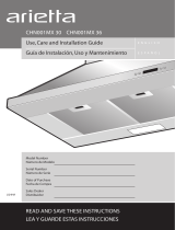
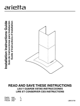
Ductwork and wiring locations
• Determine the exact location of the vent hood.
• The height installation is determined by the image shown above. Mark the location.
8’ Ceiling: 30” (minimum)
10’ Ceiling: 35” (minimum)
h
h
Minimum
Height
25-3/16”
36”
The vent hood must be installed above the cooking surface at 30" (minimum) if installed under an 8’ ceiling, or at
35” (minimum) if installed under a 10’ ceiling.
The hood may be installed vented to the outdoors, or it can be installed for recirculating operation (recirculating
accessories not supplied with the hood).
This hood must not be installed over any professional cooktop / range.
Removing the packaging
CAUTION: Remove the carton carefully. Wear gloves to protect against sharp edges.
WARNING: Remove the protective film covering the product before putting into operation.
Installing preparation
Install the 8” round transition as shows the image below. The installation screws and the 8” round transition }
are included on the hood package.
8”

12
Ceiling Support Structures
• At the hood location, install 2"x 4" cross framing
between ceiling joists as shown. (2"x 4" are
required to support the weight of the hood.)
• Arrange cross framing in the ceiling to suit the
existing structure.
• Your ceiling joists will be like one of the following
examples.
Installation Instructions
49-80406
Printed in Italy 04-06 JR
36” Hood
Template
8-1/2
?
Dia.
Cuta 1 ? Dia.
Wire Access
Hole
Cuta 1 ? Dia.
Wire Access
Hole
Drill 3/16”
Pilot Holes
Approx. 1 1/2”
Deep
Drill 3/16”
Pilot Holes
Approx. 1 1/2”
Deep
10 1/4” to
Centerline
of Holes
8 1/4” to
Centerline
of Holes
FRONT OF HOOD
8 1/4” to
Centerline
of Holes
NOTE: Do not cut the duct
opening shown on the template
for the recirculating installation.
Advance planning
• Determine the exact location of the vent hood.
• Locate the template packed with the literature.
• Plan the route for venting exhaust to the outdoors.
• Use the shortest and straightest duct route possible. For satisfactory performance duct run should not exceed
100’ equivalent length for any duct configurations.
• Refer to “Duct Fittings” chart to compute the maximum permissible length for duct runs to the outdoors.
• Use 8" round metal ductwork only.
• Installation will be easier if the vent hood is installed before the cook-top and countertop are installed.
Top view – ceiling joists at angle to front of hood
10-1/16? install cross-framing
symmetrically over duct/cooktop
centerline
16? joist
spacing
7-1/16?
8? duct
Front
of
hood
2x4 cross
framing
Cooktop
outline
Align duct
to center of
cooktop
EXAMPLE C
Top view – ceiling joists run perpendicular to front of hood
10-1/16? install
cross-framing
symmetrically over
duct/cooktop
centerline
16? joist
spacing
7-1/16?
8? duct
Front
of
hood
2x4 cross
framing
Cooktop
outline
Align duct
to center of
cooktop
EXAMPLE B
Top view – ceiling joists parallel to front of hood
10-1/16
?
Install cross-framing
symmetrically over
duct/cooktop
centerline
16? joist
spacing
7-1/16?
8” duct
Front
of
hood
2x4 cross
framing
Cooktop
outline
Align duct
to center of
cooktop
EXAMPLE A

13
Installation Instructions
Place the Glass Canopy onto
the hood. 2 people are
recommended to do this.
Place glass brackets using 2
screws by side.
Insert the plastic gaskets on
each side of the hood.
(rear and front)
Place upper duct covers
sliding through until spring
sounds “click”. Then verify
Place lower duct covers
using one plastic bracket at
each vertex. (4 needed)
Attach the vertical duct cover
supports using 4 screws. Place
each spring using a screw by side.
click !
Attach the assembly to the
support fixed on the ceiling
Assure with screws (16)
Mark with a pencil the hole
locations for screws in the
ceiling.
Place the template in the ceiling
considering the instructions for
ceiling support structures.
Fix the upper horizontal
support with 4 wood screws.
Attach the vertical supports (inf)
(A) to the hood. Then attach
horizontal support (B) (inf)
4 wood screws
(B)
(A)
16 assembly screws
8 assembly screw
2 /side
Attach a second vertical
support set to adjust the
vertical distance.
16 assembly screws
The lower duct cover shall
be secured to rangehood by
4 screws.

14
Installation Instructions
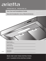
Ceiling ducting
• Use the template previously installed to prepare a 8-½” hole in the ceiling for ductwork.
4
12
/16“ (At least)
8’ Ceiling: 30” (minimum)
10’ Ceiling: 35” (minimum)
8
1
/2“
Connecting the ductwork
• Install ductwork, making connections in the direction of airflow as illustrated.
• Push duct over the exhaust outlet.
• Wrap all duct joints and the flange connections with duct tape for an airtight seal.
• Make the same connection in the wall or ceiling vent exit.
Airflow
Duct tape
over seam

15
Installation Instructions
Making the electrical connections
WARNING:
ELECTRICAL SHOCK HAZARD
TURN OFF POWER CIRCUIT AT THE SERVICE PANEL BEFORE WIRING THIS UNIT.
120 V, 15 OR 20 AMP CIRCUIT REQUIRED.
IF HOUSE WIRING IS NOT A 3 WIRE INSTALLATION (NEUTRAL, LINE AND GROUND), A GROUND MUST BE
PROVIDED BY THE INSTALLER. WHEN HOUSE WIRING IS ALUMINUM, BE SURE TO USE U.L. APPROVED
ANTI-OXIDANT COMPOUND AND ALUMINUM-TO-COPPER CONNECTORS.
ELECTRICAL GROUNDING INSTRUCTIONS
THIS APPLIANCE IS FITTED WITH AN ELECTRICAL JUNCTION BOX WITH THREE WIRES, THE WIRE COLOR
GREEN / YELLOW SERVES TO GROUND THE APPLIANCE. TO PROTECT YOU AGAINST ELECTRIC SHOCK,
THE GREEN/YELLOW WIRE MUST BE CONNECTED TO THE GROUNDING WIRE IN YOUR HOME ELECTRICAL
SYSTEM, AND IT MUST UNDER NO CIRCUMSTANCES BE CUT OR REMOVED. FAILURE TO DO SO CAN RESULT
IN DEATH OR ELECTRICAL SHOCK.
• Remove junction box cover and knockout on the top left side.
Junction box
cover
Knockout

16
Installation Instructions
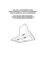
• Electrical connections:
o To connect the “Neutral”, joint by a wire nut the white wire (from the conduit) to the white wire from the
junction box.
o To connect the “Line”, joint by a wire nut the black wire (from the conduit) to the black wire from the junction
box.
o To connect the “Ground”, joint by a wire nut the Green/Yellow wire (from the conduit) to the Green/Yellow
wire from the junction box.
• Push wires into junction box.
I
MPORT
ANT: Be sure wires are not pinched
• Secure junction box cover with original screws.
• Secure the metal electrical conduit to the junction box by the UL approved conduit fitting.
Metal electrical
conduit
House
wiring
UL listed
wire nut

17
Use And Care Instructions
Use and Care Instructions
Before using your hood read this manual carefully. The information on the following pages will help you operate
and maintain your Dekor Glass hood properly. Keep it handy to answer your questions.
If you receive a damaged hood contact immediately your dealer (builder) that sold you the hood.
To obtain service, see the consumer service pages in the back of this manual. First contact the people who serviced
your appliance, explain why you are not pleased. In most cases, this will solve the problem. If are not pleased, refer
to the warranty page and write all the details including your phone number.
1 Control panel
2 Halogen lamps
3 Cover lamp
4 Grease filter
5 Grease filter release
6 Duct cover
7 Duct cover holes
8 Glass Canopy

18
Use And Care Instructions
Control and features
This hood is equipped with an electronic motor and lamp control. The control is able to set 3 different fan speeds,
turn ON/OFF light and has a timer function. In the following drawing are described the main key functions.
1. Timer Key
o The default timer setting is 10 minutes, and it can be adjusted between 20 minutes and 1
minute.
o After pressing the timer key, the control enters to a timer setup mode, and user can adjust the
timer countdown time with the “-” and “+” keys within 5 seconds. The timer can be initiated
immediately pressing the timer key, after setting the timer duration or pressing the timer key
twice (default 10 minutes setting).
o If not action occurs within 5 seconds the countdown will start.
o
During the
timer setup the “-” and “+” keys are dedicated to the timer and no motor action will
occur.
o Once initiated the timer, it can be cancelled by pressing the timer key again.
2. Light Key
o Press lamp key to turn ON the light (Lamp state previously OFF).
o Press lamp key to turn OFF the light (Lamp state previously ON).
3. Display
Shows the hood settings.
h4)-%2h+%9 hh+%9
h,)'(4h+%9 hh+%9
$)30,!9
#HARCOAL'REASEFILTER
1 2 3
#HARCOAL'REASEFILTER
1 2 3
hh+%9
hh+%9
h4)-%2h+%9 h,)'(4h+%9
$)30,!9

19
Use And Care Instructions
4. “-” Key. Speed Decrease / OFF
o This key is used to decrease the fan speed, or turn OFF the fan.
o The fan will turn OFF if the “-” key is pressed and the hood was in the rst speed.
o If the fan is at second speed and the “-” key is pressed, the fan will be set to rst speed.
o If the fan is at third speed and the “-” key is pressed, the fan will be set to second speed.
o If the fan is OFF and the “-” key is pressed, the control backlight will light up.
5. “+” Key. Speed Increase / ON
o This key is used to increase the fan speed, or turn ON the fan.
o The fan will turn ON if the “+” key is pressed and the hood was OFF.
o If the fan is at rst speed and the “+” key is pressed, the fan will be set to second speed.
o If the fan is at second speed and the “+” key is pressed, the fan will be set to third speed.
o If the fan is at third speed and the “+” key is pressed, a beep will sound.
SPECIAL FUNCTIONS
Clock programming
• The clock can be reprogrammed at any time except during an active timed function.
• The clock can be displayed in a twelve hour format and valid clock times are from 1:00 to 12:59.
• The clock can be reprogrammed pressing the “Timer” key for 5 seconds, and after, the clock can be
adjusted with the “+” and “-” keys. Colon “:” will ash indicating clock programming mode.
• The
user
can have minute increments / decrements of 1 minute, but if the user keep pressing the “+”/”-”
keys for
more than 1 second, the increments / decrements will be of 5 minutes. During this option the
control will round to the nearest 5 minutes.
• The user can nish on reprogramming the clock pressing the “timer” key.
• After
1 minute of no key pressed the control will accept the programmed clock time and will add one
minute to the set clock.
Grease lter saturation alarm
• After thirty fan functional hours, the display will show “Grease Filter” if the fan is active. When this icon
is shown in the display, the grease lters installed are required to be washed.
• To reset the grease lter saturation alarm the user must press the “+” key for 5 seconds, after this action
the icon “grease lter” is not display, and the hood has the normal display operation.

20
Use And Care Instructions
Charcoal lter saturation alarm (Recirculating accessories)
• After one hundred and twenty functional hours of the fan, the display will show “Charcoal Filter” if the fan
is active. When this icon ashes on display, the charcoal lters installed are required to be replaced or
reactivated.
• To reset the grease lter saturation indication the user must press the “-” key for 5 seconds, after this time
the icon “charcoal lter” is not display and the hood has the normal display operation.
Audible signal activation and deactivation
• The audible signals can be activated or deactivated pressing the “Light” key for 5 seconds.
• If the audible signal is activated, a tone must sound and the “Snd” symbol must appear on the display for 2
second.
• If the
audible signal is deactivated, the “Snd” symbol must appear on the display for 2 second and no sound
must sound.
Charcoal lter inclusion and exclusion (Recirculating accessories)
• The charcoal lter inclusion or exclusion can be set by pressing the “-” and “+” keys at the same time for 5
seconds.
• The Inclusion or exclusion of charcoal lter must be selected while the lamps and the motor are OFF.
•
When the charcoal has been excluded, the charcoal lter alarm is disabled.
Heat sensor
• The control is equipped with a heat sensor that will turn on the blower at second speed if excessive heat
occurs (over 70°C) surrounding the control area.
• If the blower is OFF or if it is operating at rst speed, the blower will be set automatically to second speed.
• During this state, the user may raise the blower speed to third speed but can not decrease the speed.
• When the
temperature level on the hood drops to normal, the blower will operate in the setting dened by
the user before the alarm occured.
/