Page is loading ...


Important User Information Because of the variety of uses for the product described in this publication,
those responsible for the application and use of this control equipment
must satisfy themselves that all necessary steps have been taken to assure
that each application and use meets all performance and safety
requirements, including any applicable laws, regulations, codes and
standards.
The illustrations, charts, sample programs and layout examples shown in
this guide are intended solely for purposes of example. Since there are
many variables and requirements associated with any particular
installation, Allen-Bradley Company does not assume responsibility or
liability (to include intellectual property liability) for actual use based upon
the examples shown in this publication.
Allen-Bradley publication SGI-1.1 Safety Guidelines for the Application,
Installation, and Maintenance of Solid-State Control (available from your
local Allen-Bradley office), describes some important differences between
solid-state equipment and eletromechanical devices that should be taken
into consideration when applying products such as those described in this
publication.
Reproduction of the contents of this copyrighted publication, in whole or in
part, without written permission of the Allen-Bradley Company, Inc. is
prohibited.
Throughout this manual we use notes to make you aware of safety
considerations:
!
ATTENTION: Identifies information about practices or
circumstances that can lead to personal injury or death, property
damage or economic loss.
Attentions help you:
• identify a hazard
• avoid the hazard
• recognize the consequences
Important: Identifies information that is especially important for
successful application and understanding of the product.

Document Update
1336 FORCE AC Drive User Manual
This document provides new and updated material for the 1336 FORCE
Adjustable Frequency AC Drive User Manual, publication 1336
FORCE-5.12, dated September, 1998. Please place this document with
your manual for future reference.
HIM Upload/Download Errors
The following information describes the possible errors that can be encountered
during a HIM Upload/Download procedure.
HIM Upload/Download Errors
Motor Control Board (v6.xx)
The following changes should be noted if a v6.xx Motor Control Board is being
used.
Fault Name Error Displayed Probable Cause Action
HIM -> Drive ERROR 1 The HIM calculated a checksum for the file to be
downloaded, then checked the EEPROM checksum of the
download. The checksums did not match, indicating the file
stored in the HIM is invalid and the download was not
successful.
Upload a valid, uncorrupted file from the source
drive and then repeat the download.
ERROR 2 The number of parameters in the HIM file is different than
the number of parameters in the drive file. The smaller of
the two numbers is the number of parameters downloaded.
The last downloaded parameter number is displayed.
Verify that the correct file is being downloaded to
the correct drive, then press the Enter key.
Manually reprogram parameters with numbers
higher than the last number downloaded or whose
values were incorrect.
ERROR 3 The file in the HIM is for a different type of drive than the
drive to which it is connected (i.e. 1336 FORCE file to 1336
IMPACT drive). Downloads can only occur between like
drive types.
None - Download not allowed.
ERROR 4 The value just transferred to the drive is an illegal value (out
of range, too high or too low) for the parameter.
Record the parameter number displayed and then
press Enter to continue the download. Manually
reprogram all recorded parameters after the
download is complete.
ERROR 5 The download was attempted while the drive was running. Stop the drive and repeat the download attempt.
ERROR 6 The file in the HIM is for a different HP or voltage drive than
the drive to which it is connected (i.e. 1336 FORCE 10 HP
file to 1336 FORCE 15 HP drive).
If the download is desired, press the Enter key. If
not desired, press the ESCape key to end the
download
Drive -> HIM ERROR 1 The HIM calculated a checksum as the file was uploaded
and compared it to the HIM file checksum stored after the
upload. The checksums did not match, indicating the
upload was not successful and the HIM file is now
corrupted.
Repeat the Upload.

2 1336 FORCE AC Drive User Manual
Page 1–6
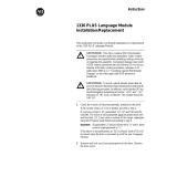
The table has been updated to include v6.xx of the Motor Control Board.
Software Compatibility
MOTOR CONTROL BOARD
PLC
COMM
ADAPTER
BOARD
v1.xx
v1.xx
v2.xx v3.xx v5.xx/v6.xx
Compatible Not Compatible Not Compatible
Not Compatible
v2.xx Not Compatible
Compatible
Compatible with exception:
✘ Torque Stop Configuration #58
non–functional.
✘ Service Factor #94 non–functional.
✘ Feedback Device Type #150
mode 7 non–functional.
✘ Calculated Torque #267
non–functional.
v3.xx
Compatible with exception:
✘ Drive Comm #9–19 non–linkable.
✘ Drive Comm Tx/Rx #14–19 max
value 219.
✘ Torque Stop Configuration #58 not
available.
✘ Service Factor #94 not available.
✘ Feedback Device Type #150 mode
7 not available.
✘ Calculated Torque #267 not
available.
Compatible with exception:
✘ Drive Comm #9–19 non–linkable.
✘ Drive Comm Tx/Rx #14–19 max
value 219.
✘ Torque Stop Configuration #58 not
a
vailable.
✘ Service Factor #94 not available.
✘ Feedback Device Type #150 mode
7 not available.
✘ Calculated Torque #267 not
available.
✘ Precharge Timeout #225 min
value 0.
✘ Perunit Motor Voltage #186 not
available.
✘ Transistor Diagnostics #257 bit 12
not available.
✘ Iq Rate Limit #181 max value 30%.
✘ Motor Overload Select #92 min
value 150%.
✘ Motor Poles #233 max value 12.
✘ Base Motor Speed #229 max value
6000.
Not Compatible
Compatible with exception:
✘ V3.04 VP must be used with V3.03
AP and V3.03 Language or higher
for B800 ‘H Frame’ drive support.
Compatible with exception:
✘ V3.04 VP must be used with V3.03
AP and V3.03
Language or higher
for B800 ‘H Frame’ drive support.
✘ Perunit Motor Current #185 not
available.
✘ Perunit Motor Current #186 not
available.
✘ Transistor Diagnostics #257 bit 12
not available.
✘ Iq Rate Limit #181 max value 30%
✘ Motor Overload Select #92 min
value 150%.
✘ Motor Poles #233 max value 12.
✘ Base Motor Speed #229 max va
lue
6000.
v5.xx
Not Compatible
Compatible with exception:
✘ Torque Stop Configuration #58
non–functional.
✘ Service Factor #94 non–functional.
✘ Feedback Device Type #150
mode 7 non–functional.
✘ Calculated Torque #267
non–functional.
✘ Perunit Motor Current #185 non–
functional.
✘ Perunit Motor Voltage #186 non–
functional.
✘ Transistor Diagnostics #257 bit 12
non–functiona
l.
Compatible
Compatible with exception:
✘ V3.04 VP must be used with V3.03
AP and V3.03 Language or higher
for B800 ‘H Frame’ drive support.
✘ Perunit Motor Current #185 non–
functional.
✘ Perunit Motor Voltage #186 non–
functional.
✘ Transistor Diagnostics #257 bit 12
non–functional.
Key:
VP = Velocity Processor CP = Current Processor
MCC = Main Control Board Language Module DP = Domino Processor on PLC Comm
APL = PLC Comm Language Module SAL = Std. Adapter Language Module
AP = Application Processor on PLC Comm SA = Std Adapter Processor

1336 FORCE AC Drive User Manual 3
Page 1–7
The table has been updated to include v6.xx of the Motor Control Board. A
note was added to v5.xx of the Standard Adapter Board.
MOTOR CONTROL BOARD
STANDARD
ADAPTER
BOARD
v1.xx
v1.xx
v2.xx v3.xx v5.xx/6.xx
Not Compatible
Compatible
Compatible
Compatible with exception:
✘ Torque Stop Configuration #58
non–functional.
✘ Service Factor #94 non–functional.
✘ Feedback Device Type #150
mode 7 non–functional.
✘ Calculated Torque #267
non–functional.
v3.xx
Compatible with exception:
✘ Drive Comm #9–19 non–linkable.
✘ Drive Comm Tx/Rx #14–19 max
value 219.
✘ Torq ue Stop Configuration #58 not
available.
✘ Service Factor #94 not available.
✘ Feedback Device Type #150 mode
7 not available.
✘ Calculated Torque #267 not
available.
✘ Precharge Timeout #225 min value 0
Compatible with exception:
✘ Drive Comm #9–19 non–linkable.
✘ Drive Comm Tx/Rx #14–19 max
value 219.
✘
Torq ue Stop Configuration #58 not
available.
✘ Service Factor #94 not available.
✘ Feedback Device Type #150 mode
7 not available.
✘ Calculated Torque #267 not available.
✘ Precharge Timeout #225 min value 0.
✘ Perunit Motor Current #185 not
available.
✘ Perunit Motor Voltage #186 not
available.
✘ Transistor Diagnostics #257
bit 12
not available.
✘ Iq Rate Limit #181 max value 30%.
✘ Motor Overload Select #92 min
value 150%.
✘ Motor Poles #233 max value 12.
✘ Base Motor Speed #229 max val 6000.
Not Compatible
Compatible with exception:
✘ V3.04 VP must be used with V3.03
AP and V3.03 Language or higher
for B800 ‘H Frame’ drive support.
✘ Perunit Motor Current #185 not
a
vailable.
✘ Perunit Motor Voltage #186 not
available.
✘ Transistor Diagnostics #257 bit 12
not available.
✘ Iq Rate Limit #181 max value 30%
✘ Motor Overload Select #92 min value
150%.
✘ Motor Poles #233 max value 12.
✘ Base Motor Speed #229 max val 6000.
v4.xx
Not Compatible
Compatible with exception:
✘ Torque Stop Configuration #58
non–functional.
✘ Service Factor #94 non–functional.
✘ Feedback Device Type #150
mode 7 non–functional.
✘ Calculated Torque #267
non–functional.
Compatible with exception:
✘ V3.04 VP must be used with V4.02
SA and V4.02 Language or higher
for B800 ‘H Frame’ drive support.
Compatible with exception:
✘ V5.xx VP must be used with V4.02
AP
and V4.02 Language or higher
for B800 ‘H Frame’ drive support.
✘ Perunit Motor Current #185 not
available.
✘ Perunit Motor Voltage #186 not
available.
✘ Transistor Diagnostics #257 bit 12
not available.
✘ Iq Rate Limit #181 max value 30%
✘ Motor Overload Select #92 min
value 150%.
✘ Motor Poles #233 max value 12.
✘ Base Motor Speed #229 max v
alu 6000.
v5.xx Not Compatible
Compatible with exception:
✘ Torque Stop Configuration #58
non–functional.
✘ Service Factor #94 non–functional.
✘ Feedback Device Type #150
mode 7 non–functional.
✘ Calculated Torque #267 non–functi.
✘ Perunit Motor Curr #185 non–funct.
✘ Perunit Motor Volt #186 non–funct.
✘ Transistor Diag. #257 bit 12 non–funct.
Compatible with exception:
✘ V3.04 VP MUST be used with V3.0
3 AP
and V3.03 Language or higher for B800
‘H Frame’ drive support.
✘ Calculated Torque #267 non–functi.
✘ Perunit Motor Curr #185 non–funct.
✘ Perunit Motor Volt #186 non–funct.
✘ Transistor Diag. #257 bit 12 non–funct.
v5.xx - Compatible.
v6.xx - Drive to drive communications
only compatible at 125k baud,
Not Compatible at 250k or 500k.

4 1336 FORCE AC Drive User Manual
Pages 3–20 through 3–24
GPT information does not apply.
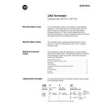
Page 5–31
Important note added to “Drive Link Baud Rate” description.
Important: If a v6.xx drive is added to the
drive link that has v5.xx or less, it will only
operate at 125k baud. If all drives on the
drive link are v6.xx, it can operate at 250k
and 500k baud.
Drive Link Baud Rate
[D2D Baud Rate]
Parameter Number 10
Parameter Type Sink
Display Units Kbaud
Drive Units None
Factory Default 0
Minimum Value 0
Maximum Value 2
This word parameter specifies the baud
rate used on the drive-to-drive link (CAN)
communication interface as follows:
00H = 125K baud
01H = 250K baud
02H = 500K baud
www.rockwellautomation.com
Americas: Rockwell Automation, 1201 South Second Street, Milwaukee, WI 53204-2496 USA, Tel: (1) 414.382.2000, Fax: (1) 414.382.4444
Europe/Middle East/Africa: Rockwell Automation, Vorstlaan/Boulevard du Souverain 36, 1170 Brussels, Belgium, Tel: (32) 2 663 0600, Fax: (32) 2 663 0640
Asia Pacific: Rockwell Automation, Level 14, Core F, Cyberport 3, 100 Cyberport Road, Hong Kong, Tel: (852) 2887 4788, Fax: (852) 2508 1846
Power, Control and Information Solutions Headquarters
Publication 1336 FORCE-5.12DU2 – February, 2007 P/N 74002-113-01 (03)
Supersedes 1336 FORCE-5.12DU2 dated February, 2006 Copyright © 2007 Rockwell Automation, Inc. All rights reserved. Printed in USA
U.S. Allen-Bradley Drives Technical Support - Tel: (1) 262.512.8176, Fax: (1) 262.512.2222, Email: suppor[email protected].rockwell.com, Online: www.ab.com/support/abdrives

Summary of Changes
Summary of Changes
Summary of Manual Changes The 5.01 release of the 1336 FORCE 5.12 User Manual contains some new
and updated information. The new and updated information is summarized
in the table below. For further information, refer to the page numbers
provided.
Description of New or Updated Information Page Type
H frame dimensions added 2-7 New
Line fuse ratings updated 2-7 Clarification
Motor Cable requirements added 2-16 New
H frame terminal block added 2-22 New
Figure 2–17 upgraded 2-29 Clarification
H Frame Terminal Block Location added 2-34 New
Frame D ControlNet connection info added 2-43 New
ControlNet Parameter Table added 5-24 New
Parameter 71 updated 5-35 Clarification
Parameter 92 updated 5-39 Clarification
Parameter 185 added 5-51 New
Parameter 186 added 5-52 New
Parameter 223 updated 5-53 Clarification
Parameter 224 updated 5-53 Clarification
Parameter 229 updated 5-54 Clarification
Parameter 233 updated 5-54 Clarification
Parameter 257 updated 5-57 Clarification
Parameter 258 updated 5-57 Clarification
Parameter 259 updated 5-57 Clarification
Parameter 294 updated 5-62 Clarification
Parameter 385 updated 5-76 Clarification
Understanding Precharge and Ridethru Faults 6–9 New
Understanding the Bus Voltage Tracker 6–15 New
Power structure and transistor Diag tests 6–20 New
Sequential Torque Block Tuning 6–24 New
H Frame Motor cable restrictions added A-4 New
B/C 700 & B/C 800 Derating Guidelines added A–15 New
700 – 800 HP Schematic added A–25 New
Software Block Diagram updated A–32 Clarification
Torque Block Firmware Diagram updated A–45 Clarification
Lithium Battery Disposal information added A–54 New
CE mechanical configuration diagram added B–5, B–6, B–7 New
Spare Part Appendix added D-1 New

This Page Intentionally Blank

Table of Contents
i
Introduction Chapter 1
Manual Objectives 1-1. . . . . . . . . . . . . . . . . . . . . . . . . . . . . . . . . . . . . . . . . . . . .
Who Should Use This Manual 1-1. . . . . . . . . . . . . . . . . . . . . . . . . . . . . . . . . . .
Terminology 1-1. . . . . . . . . . . . . . . . . . . . . . . . . . . . . . . . . . . . . . . . . . . . . . . . .
Standard Drive Features 1-2. . . . . . . . . . . . . . . . . . . . . . . . . . . . . . . . . . . . . . . .
Performance Specifications 1-2. . . . . . . . . . . . . . . . . . . . . . . . . . . . . . . . . . . . . .
Control Specifications 1-2. . . . . . . . . . . . . . . . . . . . . . . . . . . . . . . . . . . . . . . . . .
Options 1-3. . . . . . . . . . . . . . . . . . . . . . . . . . . . . . . . . . . . . . . . . . . . . . . . . . . . .
Protective Features 1-3. . . . . . . . . . . . . . . . . . . . . . . . . . . . . . . . . . . . . . . . . . . .
Environmental Specifications 1-4. . . . . . . . . . . . . . . . . . . . . . . . . . . . . . . . . . . .
Electrical Specifications 1-4. . . . . . . . . . . . . . . . . . . . . . . . . . . . . . . . . . . . . . . .
Feedback Devices 1-5. . . . . . . . . . . . . . . . . . . . . . . . . . . . . . . . . . . . . . . . . . . . .
Software Compatibility 1-6. . . . . . . . . . . . . . . . . . . . . . . . . . . . . . . . . . . . . . . . .
Installation/Wiring Chapter 2
Chapter Objectives 2-1. . . . . . . . . . . . . . . . . . . . . . . . . . . . . . . . . . . . . . . . . . . .
Mounting 2-1. . . . . . . . . . . . . . . . . . . . . . . . . . . . . . . . . . . . . . . . . . . . . . . . . . . .
Dimensions 2-2. . . . . . . . . . . . . . . . . . . . . . . . . . . . . . . . . . . . . . . . . . . . . . . . . .
Input/Output Ratings 2-7. . . . . . . . . . . . . . . . . . . . . . . . . . . . . . . . . . . . . . . . . . .
AC Supply Source 2–7. . . . . . . . . . . . . . . . . . . . . . . . . . . . . . . . . . . . . . . . . . . . .
Input Devices 2–9. . . . . . . . . . . . . . . . . . . . . . . . . . . . . . . . . . . . . . . . . . . . . . . . .
Drive Output Disconnection 2–10. . . . . . . . . . . . . . . . . . . . . . . . . . . . . . . . . . . . .
Input Power Conditioning 2–10. . . . . . . . . . . . . . . . . . . . . . . . . . . . . . . . . . . . . . .
Input Fusing 2–10. . . . . . . . . . . . . . . . . . . . . . . . . . . . . . . . . . . . . . . . . . . . . . . . . .
Electrical Interference – EMI/RFI 2–12. . . . . . . . . . . . . . . . . . . . . . . . . . . . . . . . .
RFI Filtering 2–13. . . . . . . . . . . . . . . . . . . . . . . . . . . . . . . . . . . . . . . . . . . . . . . . .
Grounding 2–14. . . . . . . . . . . . . . . . . . . . . . . . . . . . . . . . . . . . . . . . . . . . . . . . . . .
Power Cabling 2–16. . . . . . . . . . . . . . . . . . . . . . . . . . . . . . . . . . . . . . . . . . . . . . . .
Wire Size and Type 2–16. . . . . . . . . . . . . . . . . . . . . . . . . . . . . . . . . . . . . . . . . . . .
Lug Kits 2–17. . . . . . . . . . . . . . . . . . . . . . . . . . . . . . . . . . . . . . . . . . . . . . . . . . . . .
Power Wiring 2–20. . . . . . . . . . . . . . . . . . . . . . . . . . . . . . . . . . . . . . . . . . . . . . . .
Control Wiring 2–23. . . . . . . . . . . . . . . . . . . . . . . . . . . . . . . . . . . . . . . . . . . . . . .
Encoder Connections 2–24. . . . . . . . . . . . . . . . . . . . . . . . . . . . . . . . . . . . . . . . . . .
Drive to Drive Communication 2–24. . . . . . . . . . . . . . . . . . . . . . . . . . . . . . . . . .
Standard Adapter Board 2–26. . . . . . . . . . . . . . . . . . . . . . . . . . . . . . . . . . . . . . . .
Control & Signal Wiring (Standard Adapter Board) 2–26. . . . . . . . . . . . . . . . . . .
Interface Board Installation & Removal 2–27. . . . . . . . . . . . . . . . . . . . . . . . . . . .
Standard Adapter Analog Inputs 2–28. . . . . . . . . . . . . . . . . . . . . . . . . . . . . . . . . .
Standard Adapter Analog Outputs 2–29. . . . . . . . . . . . . . . . . . . . . . . . . . . . . . . .
Standard Adapter Discrete Outputs 2–29. . . . . . . . . . . . . . . . . . . . . . . . . . . . . . . .
Pulse Input (Standard Adapter Equipped Drives) 2–29. . . . . . . . . . . . . . . . . . . .
Starting & Stopping the Motor (Standard Adapter Equipped Drives) 2–32. . . . .
Control Interface Option – TB3 2–33. . . . . . . . . . . . . . . . . . . . . . . . . . . . . . . . . .

Table of Contents
ii
Control & Signal Wiring (PLC Comm Adapter Board) 2–40. . . . . . . . . . . . . . . .
Switch Settings (PLC Comm Board) 2–41. . . . . . . . . . . . . . . . . . . . . . . . . . . . . .
Discrete Outputs (PLC Comm Adapter) 2–42. . . . . . . . . . . . . . . . . . . . . . . . . . . .
Discrete Inputs (PLC Comm Adapter) 2–42. . . . . . . . . . . . . . . . . . . . . . . . . . . . .
Control Scheme 2–45. . . . . . . . . . . . . . . . . . . . . . . . . . . . . . . . . . . . . . . . . . . . . . .
Computer Connections (Frame D Drives) 2–45. . . . . . . . . . . . . . . . . . . . . . . . . . .
ControlNet Connections (Frame D Drives) 2–45. . . . . . . . . . . . . . . . . . . . . . . . . .
Configuration (PLC Comm Adapter) 2–46. . . . . . . . . . . . . . . . . . . . . . . . . . . . . .
Programming Terminals Chapter 3
Chapter Objectives 3-1. . . . . . . . . . . . . . . . . . . . . . . . . . . . . . . . . . . . . . . . . . . .
HIM Description 3-1. . . . . . . . . . . . . . . . . . . . . . . . . . . . . . . . . . . . . . . . . . . . . .
HIM Module Removal 3-4. . . . . . . . . . . . . . . . . . . . . . . . . . . . . . . . . . . . . . . . .
HIM Operation 3-4. . . . . . . . . . . . . . . . . . . . . . . . . . . . . . . . . . . . . . . . . . . . . . .
HIM Programming Steps 3-19. . . . . . . . . . . . . . . . . . . . . . . . . . . . . . . . . . . . . . . .
GPT Description 3-20. . . . . . . . . . . . . . . . . . . . . . . . . . . . . . . . . . . . . . . . . . . . . .
Keypad Description 3-21. . . . . . . . . . . . . . . . . . . . . . . . . . . . . . . . . . . . . . . . . . . .
GPT Operation 3-22. . . . . . . . . . . . . . . . . . . . . . . . . . . . . . . . . . . . . . . . . . . . . . .
GPT Programming Options 3-24. . . . . . . . . . . . . . . . . . . . . . . . . . . . . . . . . . . . . .
Start–Up Chapter 4
Introduction 4-1. . . . . . . . . . . . . . . . . . . . . . . . . . . . . . . . . . . . . . . . . . . . . . . . . .
Safety Precautions 4-1. . . . . . . . . . . . . . . . . . . . . . . . . . . . . . . . . . . . . . . . . . . . .
Required Tools and Equipment 4-2. . . . . . . . . . . . . . . . . . . . . . . . . . . . . . . . . . .
Drive Information 4-3. . . . . . . . . . . . . . . . . . . . . . . . . . . . . . . . . . . . . . . . . . . . .
General 4-4. . . . . . . . . . . . . . . . . . . . . . . . . . . . . . . . . . . . . . . . . . . . . . . . . . . . .
Pre–Power Checks 4-4. . . . . . . . . . . . . . . . . . . . . . . . . . . . . . . . . . . . . . . . . . . . .
Power On 4-5. . . . . . . . . . . . . . . . . . . . . . . . . . . . . . . . . . . . . . . . . . . . . . . . . . . .
Startup Configuration Procedures 4-6. . . . . . . . . . . . . . . . . . . . . . . . . . . . . . . . .
Quick Startup Procedure 4-7. . . . . . . . . . . . . . . . . . . . . . . . . . . . . . . . . . . . . . . .
Manual Startup Mode 4-10. . . . . . . . . . . . . . . . . . . . . . . . . . . . . . . . . . . . . . . . . .
Communication Configuration 4-17. . . . . . . . . . . . . . . . . . . . . . . . . . . . . . . . . . .
Drive to Drive Communication 4-17. . . . . . . . . . . . . . . . . . . . . . . . . . . . . . . . . .
I/O Communication Configuration 4-20. . . . . . . . . . . . . . . . . . . . . . . . . . . . . . .
External Control Link Configuration 4-21. . . . . . . . . . . . . . . . . . . . . . . . . . . . .
Analog I/O Parameter Configuration 4-23. . . . . . . . . . . . . . . . . . . . . . . . . . . . .
SCANport Analog I/O Parameter Configuration 4-27. . . . . . . . . . . . . . . . . . . .
Output Relay Configuration 4-27. . . . . . . . . . . . . . . . . . . . . . . . . . . . . . . . . . . .
Pulse Input Configuration 4-28. . . . . . . . . . . . . . . . . . . . . . . . . . . . . . . . . . . . . .
MOP Configuration 4-28. . . . . . . . . . . . . . . . . . . . . . . . . . . . . . . . . . . . . . . . . . .
SCANport Image Configuration 4-28. . . . . . . . . . . . . . . . . . . . . . . . . . . . . . . . .
SCANport Control Configuration 4-29. . . . . . . . . . . . . . . . . . . . . . . . . . . . . . . .

Table of Contents
iii
Control Interface Option 4-29. . . . . . . . . . . . . . . . . . . . . . . . . . . . . . . . . . . . . . .
Using the SCANport Image: 4-30. . . . . . . . . . . . . . . . . . . . . . . . . . . . . . . . . . . .
I/O Image Table 4-31. . . . . . . . . . . . . . . . . . . . . . . . . . . . . . . . . . . . . . . . . . . . . .
SLC to SCANport Module 4-32. . . . . . . . . . . . . . . . . . . . . . . . . . . . . . . . . . . . .
Serial Communications Module 4-33. . . . . . . . . . . . . . . . . . . . . . . . . . . . . . . . . .
Remote I/O Communications Module 4-34. . . . . . . . . . . . . . . . . . . . . . . . . . . . .
Programming Parameters Chapter 5
Introduction 5-1. . . . . . . . . . . . . . . . . . . . . . . . . . . . . . . . . . . . . . . . . . . . . . . . . .
Terminology 5-1. . . . . . . . . . . . . . . . . . . . . . . . . . . . . . . . . . . . . . . . . . . . . . . . .
Parameter Table Structure 5-2. . . . . . . . . . . . . . . . . . . . . . . . . . . . . . . . . . . . . . .
Parameter Table (Numerical) 5-3. . . . . . . . . . . . . . . . . . . . . . . . . . . . . . . . . . . .
Parameter Table (Alphabetical) 5-11. . . . . . . . . . . . . . . . . . . . . . . . . . . . . . . . . . .
Standard Adapter Parameters 5-16. . . . . . . . . . . . . . . . . . . . . . . . . . . . . . . . . . . .
PLC Comm Adapter Parameters 5-20. . . . . . . . . . . . . . . . . . . . . . . . . . . . . . . . . .
Parameter Descriptions 5-24. . . . . . . . . . . . . . . . . . . . . . . . . . . . . . . . . . . . . . . . .
ControlNet Parameters 5-80. . . . . . . . . . . . . . . . . . . . . . . . . . . . . . . . . . . . . . . . .
Troubleshooting Chapter 6
General 6-1. . . . . . . . . . . . . . . . . . . . . . . . . . . . . . . . . . . . . . . . . . . . . . . . . . . . .
Required Equipment 6-1. . . . . . . . . . . . . . . . . . . . . . . . . . . . . . . . . . . . . . . . . . .
Fault Descriptions 6-2. . . . . . . . . . . . . . . . . . . . . . . . . . . . . . . . . . . . . . . . . . . . .
Fault Code Definition 6-2. . . . . . . . . . . . . . . . . . . . . . . . . . . . . . . . . . . . . . . . . .
Main Control Board Fault Descriptions 6-3. . . . . . . . . . . . . . . . . . . . . . . . . . . .
Standard Adapter Board Fault Descriptions 6-4. . . . . . . . . . . . . . . . . . . . . . . . .
Fault/Warning Handling 6-5. . . . . . . . . . . . . . . . . . . . . . . . . . . . . . . . . . . . . . . .
Current Processor Faults & Warnings 6-7. . . . . . . . . . . . . . . . . . . . . . . . . . . . . .
Understanding Precharge and Ridethrough Faults 6-9. . . . . . . . . . . . . . . . . . . .
Understanding the Bus Voltage Tracker 6-15. . . . . . . . . . . . . . . . . . . . . . . . . . . .
Auto-Tuning Test Procedure 6-20. . . . . . . . . . . . . . . . . . . . . . . . . . . . . . . . . . . . .
Power Structure and Transistor Diagnostics Tests 6-20. . . . . . . . . . . . . . . . . . . .
Phase Rotation Tests 6-24. . . . . . . . . . . . . . . . . . . . . . . . . . . . . . . . . . . . . . . . . . .
Sequential Torque Block Tuning 6-24. . . . . . . . . . . . . . . . . . . . . . . . . . . . . . . . . .
Running the Resistance Test 6-26. . . . . . . . . . . . . . . . . . . . . . . . . . . . . . . . . . . . .
Running the Flux Test 6-29. . . . . . . . . . . . . . . . . . . . . . . . . . . . . . . . . . . . . . . . . .
Torque Block Update 6-31. . . . . . . . . . . . . . . . . . . . . . . . . . . . . . . . . . . . . . . . . . .
Velocity Loop Autotune 6-32. . . . . . . . . . . . . . . . . . . . . . . . . . . . . . . . . . . . . . . .
Hardware Testpoints 6-34. . . . . . . . . . . . . . . . . . . . . . . . . . . . . . . . . . . . . . . . . . .

Table of Contents
iv
Appendix Appendix A
Motor Cables A-1. . . . . . . . . . . . . . . . . . . . . . . . . . . . . . . . . . . . . . . . . . . . . . . . .
Cable Termination A-5. . . . . . . . . . . . . . . . . . . . . . . . . . . . . . . . . . . . . . . . . . . . .
Enclosures A-5. . . . . . . . . . . . . . . . . . . . . . . . . . . . . . . . . . . . . . . . . . . . . . . . . . .
Derating Guidelines A-7. . . . . . . . . . . . . . . . . . . . . . . . . . . . . . . . . . . . . . . . . . . .
Drive Hardware Overview A-16. . . . . . . . . . . . . . . . . . . . . . . . . . . . . . . . . . . . . .
Schematic Diagrams A-17. . . . . . . . . . . . . . . . . . . . . . . . . . . . . . . . . . . . . . . . . . .
Gate Driver Board Connections A-27. . . . . . . . . . . . . . . . . . . . . . . . . . . . . . . . . .
Sensorless Application Notes A-30. . . . . . . . . . . . . . . . . . . . . . . . . . . . . . . . . . . .
Software Block Diagram – Standard Adapter A-32. . . . . . . . . . . . . . . . . . . . . . . .
Firmware Function Overview Diagrams A-34. . . . . . . . . . . . . . . . . . . . . . . . . . . .
Battery Disposal A-54. . . . . . . . . . . . . . . . . . . . . . . . . . . . . . . . . . . . . . . . . . . . . .
CE Conformity Appendix B
EMC Directive B-1. . . . . . . . . . . . . . . . . . . . . . . . . . . . . . . . . . . . . . . . . . . . . . . .
Requirements for Conforming Installation B-1. . . . . . . . . . . . . . . . . . . . . . . . . .
Filter B-2. . . . . . . . . . . . . . . . . . . . . . . . . . . . . . . . . . . . . . . . . . . . . . . . . . . . . . .
Electrical Configuration B-3. . . . . . . . . . . . . . . . . . . . . . . . . . . . . . . . . . . . . . . .
Grounding B-3. . . . . . . . . . . . . . . . . . . . . . . . . . . . . . . . . . . . . . . . . . . . . . . . . . .
Mechanical Configuration B-4. . . . . . . . . . . . . . . . . . . . . . . . . . . . . . . . . . . . . . .
Required Knockout Assignments B-7. . . . . . . . . . . . . . . . . . . . . . . . . . . . . . . . .
User Parameter Values Appendix C
Value Table C-1. . . . . . . . . . . . . . . . . . . . . . . . . . . . . . . . . . . . . . . . . . . . . . . . . .
Spare Parts Information Appendix D
Information Location D-1. . . . . . . . . . . . . . . . . . . . . . . . . . . . . . . . . . . . . . . . . . .

Chapter
1
1–1
Introduction
Manual Objectives The purpose of this manual is to provide the user with the necessary
information to install, program, start up and maintain the 1336 FORCE
Digital AC Drive. This manual should be read in its entirety before
operating, servicing or initializing the 1336 FORCE Drive.
Who Should Use This Manual This manual is intended for qualified service personnel responsible for
setting up and servicing the 1336 FORCE AC Drive. You must have
previous experience with and a basic understanding of electrical
terminology, programming procedures, required equipment and safety
precautions before attempting any service on the 1336 FORCE Drive.
ATTENTION: Only personnel familiar with the 1336
FORCE Drive and the associated machinery should plan or
implement the installation, start–up, and subsequent
maintenance of the Drive. Failure to comply may result in
personal injury and/or equipment damage.
!
!
ATTENTION: An incorrectly applied or installed Drive
can result in component damage or a reduction in product
life. Wiring or application errors such as undersizing the
motor, incorrect or inadequate AC supply or excessive
ambient temperatures may result in damage to the Drive or
motor.
!
ATTENTION: This Drive contains ESD (Electrostatic
Discharge sensitive parts and assemblies. Static control
precautions are required when installing, testing, servicing
or repairing this assembly. Component damage may result
if ESD control procedures are not followed. If you are not
familiar with static control procedures, reference
Allen–Bradley Publication 8000–4.5.2, Guarding against
Electrostatic Damage or any other applicable ESD
protection handbook.
Terminology Detailed definitions of industrial automation and technical terms used
throughout this manual may be found in the INDUSTRIAL
AUTOMATION GLOSSARY – a guide to Allen–Bradley technical
terms, Publication AG–7.1.

Chapter 1
Introduction
1–2
Standard Drive Features The Bulletin1336 FORCE Field Oriented AC Drive is a microprocessor
controlled Digital AC Drive with the following features:
• 1 to 650 HP at 0 – 250 HZ constant torque
• Four Quadrant operation available
• High Performance Digital Velocity Loop
• Microprocessor controlled, field oriented current loop
• Simplified programming through the use of a Parameter Table that
features data entries in engineering units with English descriptions
• Nonvolatile Parameter Storage
• Extensive diagnostics, including both logic board and power
structure tests
• Time stamped nonvolatile Fault/Warning Queue
• Real Time Clock
• Reference Time Stamp
• Run Time Accumulator
• Enclosed Construction
• Multiple Communication Interfaces
• Complete Encoder Interface
• Drive to Drive Link
• SCANport
TM
Peripheral Interface
Performance Specifications
• Speed Regulation to 0.001% of top speed.
• Torque Regulation to ± 5% of rated motor torque.
• Power Loss Ride–Thru capability of two seconds.
• Flying Start: Capability of starting into a spinning motor.
• Torque Linearity 1%
• Overload Capability: 150% for 1 minute, 200% of motor rating for
10 seconds, up to inverter limit.
• Programmable Accel/Decel rates from 0 to 6553 seconds
• Current limit programmable from 200% of rated output current.
Control Specifications
• Indirect Self–Organized, Field–Oriented Control,
Current–regulated, sine coded PWM with programmable carrier
frequency.
HP Drive Rating Carrier Frequency
1–3 HP 4 kHz 1–12 kHz
7.5–30 HP 4 kHz 1–12 kHz
40–60 HP 4 kHz 1–12 kHz
75–125 HP 2 kHz 1–6 kHz
150–250 2 kHz 1–6 kHz
300–500 2 kHz 1–4 kHz
600–650 1.5 kHz 1–4 kHz
700–800 1 kHz 1–4 kHz
Refer to Derating Guidelines in the Appendix of this manual
• Output Voltage Range – 0 to rated voltage
• Output Frequency Range – 0 to 250 Hz.
• Speed Regulation with Encoder Feedback – 0.001% of Top Speed
over a 100.1 Speed Range.

Chapter 1
Introduction
1–3
• Encoderless Speed Regulation – 1% of Top Speed over a 40:1 Speed
Range.
• Accel/Decel – Independently programmable accel and decel times.
Program from 0 to 6553 seconds in 0.1 second increments.
• Current Limit – Independent Motoring and Regenerative Limit
• Inverse Time Overload Capability – Class 20 protection with
speed–sensitive response. Adjustable from 0–200% of rated output
current in 3 speed ranges – 2:1, 4:1 & 10:1. UL Certified – Meets
NEC Article 430.
Options
• Standard Adapter Board which provides:
– 2 Analog Inputs +/–10V
– 2 Analog Outputs +/– 10V
– One 4–20mA input
– One 4–20mA output
– 5 or 12 vdc pulse input
– +/– 10V reference voltages
– At Speed, Run, Fault and Alarm contacts
• PLC Communication Adapter Board which provides:
– 4 Analog Inputs +/–10V
– 4 Analog Outputs +/– 10V
– +/– 10V Reference voltages
– RIO/DH
TM
+ Communications (2 channels selectable)
– Function Blocks
• DriveTools
TM;
PC Windows
TM
based programming software
compatible with the 1336 FORCE Drive and also other
Allen–Bradley 1336 and 1395 products.
• Dynamic Braking
• AC Motor Contactor
Protective Features The 1336 FORCE Drive incorporates the following protective measures:
• Programmable Motor Overload Protection (I
2
T) investigated by UL
to comply with NEC Article 430.
• Programmable Inverter Overload Protection (IT)
• Overspeed Detection, even when operating as a torque follower.
• Programmable Stall Detection
• Peak output current monitoring to protect against excessive current
at the output due to a phase to ground or phase to phase short.
• Ground fault monitoring
• DC Bus Voltage monitoring to protect against under/over voltage
conditions.
• Power Structure Heatsink Temperature Monitoring

Chapter 1
Introduction
1–4
Environmental Specifications The following environmental guidelines apply to both the 1336 FORCE
Drive and all devices and accessories connected to the Drive.
• Ambient Operating Temperature:
IP00, Open: 0 to 50 degrees C (32 to 122 degrees F).
IP20, NEMA Type 1 Enclosed:
0 to 40 degrees C (32 to 104 degrees F).
IP65, NEMA Type 4 Enclosed:
0 to 40 degrees C (32 to 104 degrees F).
• Storage Temperature (all constructions):
–40 to 70 degrees C (–40 to 158 degrees F).
• Relative Humidity: 5 – 95% non–condensing
• Altitude: 1000m (3300 ft) without derating.
• Shock: 15g peak for 11ms duration (+ 1.0 ms).
• Vibration: 0.006 inches (0.152 mm) displacement. 1G peak.
Electrical Specifications
• Input Voltage Rating:
200 – 240VAC, Standalone, 3 Phase, +10%, –15% nominal
380 – 480VAC, Standalone, 3 Phase, +10%, –15% nominal
500 – 600VAC Standalone, 3 Phase, +10%, –15% nominal
513 – 621 VDC, Common Bus, +10%, –15% nominal
776 VDC, Common Bus, +10%, –15% nominal
• Input Power Rating:
2 – 134 KVA (230V)
2 – 437 KVA (380V)
2 – 555 KVA (460V)
2/3 – 578/694 KVA (500/600V)
• Input Frequency: 50/60HZ (±3HZ)
• Standard Output Voltage*: Four frame sizes are available. Each
frame size is line dependent and can power a motor between the
following voltages:
200 – 240 Vac (line dependent)
380 – 480 Vac (line dependent)
500 – 600 Vac (line dependent)
*If voltage required for your application is not shown, contact
Allen–Bradley for specific application.
• Output Current: 2.5 – 673A
• Output Power: 2 – 116 KVA (230V)
2 – 190 KVA (380V)
2 – 208 KVA (415V)
2 – 537 KVA (460V)
2 – 671 KVA (575V)
Note: For information on factors that could effect the power output
of the drive please refer to the Enclosure and Derating Guidelines in
the Appendix of this manual.
• Output Horsepower (Continuous):
7.5 – 650HP
• Overload Capability:
Continuous – 100% Fundamental current
1 minute – 150%

Chapter 1
Introduction
1–5
• Output Frequency Range: 0 – 250 HZ
• Output Waveform: Sinusoidal (PWM)
• Max. Short Circuit Current Rating : 200,000A rms symmetrical,
600 volts (when used with specified AC input line fuses as detailed
in Table 2.A).
• Ride Through: 2 seconds minimum
• Efficiency: 97.5% at rated amps, nominal line volts
Feedback Devices
• Encoder: Incremental, dual channel; 12 volts, 500mA,
Supply, 5/12 Volt 10ma Min Inputs, isolated with
differential transmitter, 102.5 KHz max.
Quadrature: 90° ±27° @ 25°C, Duty Cycle: 50% + 10%.
• Speed Regulation with Encoder Feedback: 0.001% of Top Speed
over a 100:1 Speed Range.
Encoderless Speed Regulation: 0.5% of Top Speed over a 40:1 Speed
Range.

Chapter 1
Introduction
1–6
Software Compatibility
MOTOR CONTROL BOARD
PLC
COMM
ADAPTER
BOARD
v1.xx
v1.xx
v2.xx v3.xx v5.xx
Compatible Not Compatible Not Compatible
Not Compatible
v2.xx Not Compatible Compatible
Compatible with exception:
✘ Torque Stop Configuration #58
non–functional.
✘ Service Factor #94 non–functional.
✘ Feedback Device Type #150
mode 7 non–functional.
✘ Calculated Torque #267
non–functional.
v3.xx
Compatible with exception:
✘ Drive Comm #9–19 non–linkable.
✘ Drive Comm Tx/Rx #14–19 max
value 219.
✘ Torque Stop Configuration #58 not
available.
✘ Service Factor #94 not available.
✘ Feedback Device Type #150 mode
7 not available.
✘ Calculated Torque #267 not
available.
Compatible with exception:
✘ Drive Comm #9–19 non–linkable.
✘ Drive Comm Tx/Rx #14–19 max
value 219.
✘ Torque Stop Configuration #58 not
available.
✘ Service Factor #94 not available.
✘ Feedback Device Type #150 mode
7 not available.
✘ Calculated Torque #267 not
available.
✘ Precharge Timeout #225 min
value 0.
✘ Perunit Motor Voltage #186 not
available.
✘ Transistor Diagnostics #257 bit 12
not available.
✘ Iq Rate Limit #181 max value 30%.
✘ Motor Overload Select #92 min
value 150%.
✘ Motor Poles #233 max value 12.
✘ Base Motor Speed #229 max value
6000.
Not Compatible
Compatible with exception:
✘ V3.04 VP must be used with V3.03
AP and V3.03 Language or higher
for B800 ‘H Frame’ drive support.
Compatible with exception:
✘ V3.04 VP must be used with V3.03
AP and V3.03 Language or higher
for B800 ‘H Frame’ drive support.
✘ Perunit Motor Current #185 not
available.
✘ Perunit Motor Current #186 not
available.
✘ Transistor Diagnostics #257 bit 12
not available.
✘ Iq Rate Limit #181 max value 30%
✘ Motor Overload Select #92 min
value 150%.
✘ Motor Poles #233 max value 12.
✘ Base Motor Speed #229 max value
6000.
v5.xx
Not Compatible
Compatible with exception:
✘ Torque Stop Configuration #58
non–functional.
✘ Service Factor #94 non–functional.
✘ Feedback Device Type #150
mode 7 non–functional.
✘ Calculated Torque #267
non–functional.
✘ Perunit Motor Current #185 non–
functional.
✘ Perunit Motor Voltage #186 non–
functional.
✘ Transistor Diagnostics #257 bit 12
non–functional.
Compatible
Compatible with exception:
✘ V3.04 VP must be used with V3.03
AP and V3.03 Language or higher
for B800 ‘H Frame’ drive support.
✘ Perunit Motor Current #185 non–
functional.
✘ Perunit Motor Voltage #186 non–
functional.
✘ Transistor Diagnostics #257 bit 12
non–functional.
Key: VP = Velocity Processor CP = Current Processor
MCC = Main Control Board Language Module DP = Domino Processor on PLC Comm
APL = PLC Comm Language Module SAL = Std. Adapter Language Module
AP = Application Processor on PLC Comm SA = Std Adapter Processor

Chapter 1
Introduction
1–7
MOTOR CONTROL BOARD
STADARD
ADAPTER
BOARD
v1.xx
v1.xx
v2.xx v3.xx v5.xx
Not Compatible
Compatible
Compatible
Compatible with exception:
✘ Torque Stop Configuration #58
non–functional.
✘ Service Factor #94 non–functional.
✘ Feedback Device Type #150
mode 7 non–functional.
✘ Calculated Torque #267
non–functional.
v3.xx
Compatible with exception:
✘ Drive Comm #9–19 non–linkable.
✘ Drive Comm Tx/Rx #14–19 max
value 219.
✘ Torque Stop Configuration #58 not
available.
✘ Service Factor #94 not available.
✘ Feedback Device Type #150 mode
7 not available.
✘ Calculated Torque #267 not
available.
✘ Precharge Timeout #225 min value 0
Compatible with exception:
✘ Drive Comm #9–19 non–linkable.
✘ Drive Comm Tx/Rx #14–19 max
value 219.
✘ Torque Stop Configuration #58 not
available.
✘ Service Factor #94 not available.
✘ Feedback Device Type #150 mode
7 not available.
✘ Calculated Torque #267 not available.
✘ Precharge Timeout #225 min value 0.
✘ Perunit Motor Current #185 not
available.
✘ Perunit Motor Voltage #186 not
available.
✘ Transistor Diagnostics #257 bit 12
not available.
✘ Iq Rate Limit #181 max value 30%.
✘ Motor Overload Select #92 min
value 150%.
✘ Motor Poles #233 max value 12.
✘ Base Motor Speed #229 max val 6000.
Not Compatible
Compatible with exception:
✘ V3.04 VP must be used with V3.03
AP and V3.03 Language or higher
for B800 ‘H Frame’ drive support.
✘ Perunit Motor Current #185 not
available.
✘ Perunit Motor Voltage #186 not
available.
✘ Transistor Diagnostics #257 bit 12
not available.
✘ Iq Rate Limit #181 max value 30%
✘ Motor Overload Select #92 min value
150%.
✘ Motor Poles #233 max value 12.
✘ Base Motor Speed #229 max val 6000.
v4.xx
Not Compatible
Compatible with exception:
✘ Torque Stop Configuration #58
non–functional.
✘ Service Factor #94 non–functional.
✘ Feedback Device Type #150
mode 7 non–functional.
✘ Calculated Torque #267
non–functional.
Compatible with exception:
✘ V3.04 VP must be used with V4.02
SA and V4.02 Language or higher
for B800 ‘H Frame’ drive support.
Compatible with exception:
✘ V5.xx VP must be used with V4.02
AP and V4.02 Language or higher
for B800 ‘H Frame’ drive support.
✘ Perunit Motor Current #185 not
available.
✘ Perunit Motor Voltage #186 not
available.
✘ Transistor Diagnostics #257 bit 12
not available.
✘ Iq Rate Limit #181 max value 30%
✘ Motor Overload Select #92 min
value 150%.
✘ Motor Poles #233 max value 12.
✘ Base Motor Speed #229 max valu 6000.
v5.xx Not Compatible
Compatible with exception:
✘ Torque Stop Configuration #58
non–functional.
✘ Service Factor #94 non–functional.
✘ Feedback Device Type #150
mode 7 non–functional.
✘ Calculated Torque #267 non–functi.
✘ Perunit Motor Curr #185 non–funct.
✘ Perunit Motor Volt #186 non–funct.
✘ Transistor Diag. #257 bit 12 non–funct.
Compatible with exception:
✘ V3.04 VP MUST be used with V3.03 AP
and V3.03 Language or higher for B800
‘H Frame’ drive support.
✘ Calculated Torque #267 non–functi.
✘ Perunit Motor Curr #185 non–funct.
✘ Perunit Motor Volt #186 non–funct.
✘ Transistor Diag. #257 bit 12 non–funct.
Compatible

Chapter 1
Introduction
1–8
This Page Intentionally Blank
/