Page is loading ...

INSTALLATION GUIDE
1131 Wireless Recessed Contact
Description
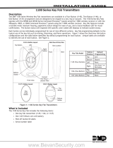
The 1131 is a wireless recessed contact that provides concealed protection for doors, windows or any other
application needing a discreet contact. As with all DMP 1100 Series transmitters, the on-board LED provides built-in
survey capability to allow for single-person installations, eliminating the requirement for an external survey kit. The
1131 transmits Alarm, Normal and Low Battery conditions.
Compatibility
The 1131 Recessed Contact operates with the XR500 Series Command Processor™ panels or XR100 Series Command
Processor™ panels using the 1100X, 1100XI or 1100XH Receiver or with the XRSuper6, XR20, and XR40 Command
Processor™ panels using the 1100D, 1100DI or 1100DH Receiver.
What is Included
The 1131 Recessed Contact includes the following items:
• One 1131 in a two-part housing consisting of the transmitter housing and face plate
• One Magnet with housing
• One 3V Lithium CR12600SE Battery
• Hardware pack
• Zone name and number label
• Serial number label
• Optional blank face plate for pre-installation tting
Serial Number
For your convenience, an additional pre-printed serial number label is included. Prior to installing the device,
record the serial number or place the pre-printed serial number label on the panel programming sheet. This number
is required during programming. As needed, use the zone name and number label to identify a specic transmitter.
Programming the Contact in the Panel
Refer to the XR500 Series Programming Guide (LT-0679), XR100 Series Programming Guide (LT-0896), or the
XRSuper6/XR20/XR40 Programming Guide (LT-0305) as needed. Program the contact as a zone in Zone Information
during panel programming. At the Serial Number: prompt, enter the eight-digit serial number, including leading
zeros. Continue to program the zone as directed in the panel programming guide.
Note: When a receiver is installed, powered up, or the panel is reset, the supervision time for transmitters is reset.
If the receiver has been powered down for more than one hour, wireless transmitters may take up to an additional
hour to send a supervision message unless tripped, tampered, or powered up. This operation extends battery life for
transmitters. A missing message may display on the keypad until the transmitter sends a supervision message.
Selecting the Proper Location (LED Survey Operation)
The 1131 provides survey capability to allow one person to conrm transmitter communication with the receiver
before installation. The 1131 Red Survey LED turns on whenever data is sent to the receiver then immediately turns
off when the receiver acknowledgement is received. Using the contact magnet is a convenient way to send data to
the receiver to conrm operation. When the magnet is moved away or brought towards the contact, the LED blinks
once to indicate proper operation. When the transmitter does not receive an acknowledgement from the receiver
the LED remains on for about 8 seconds to let you know communication is not established. Communication is also
faulty when the LED ashes multiple times in quick succession. Relocate the contact or receiver until the LED
immediately turns off indicating the transmitter and receiver are communicating properly. Proper communication
between the transmitter and receiver is veried when each time the magnet is within 1/2 inch of the transmitter
or away from the transmitter. Repeat this test to conrm ve separate consecutive LED blinks. Any indication
otherwise means proper communication has not been established. Refer to the 1100 Series Receiver installation for
full information about the survey LED.

Digital Monitoring Products 1131 Installation Guide
2
1131 Installation Guide Digital Monitoring Products
3
Mounting the Recessed Contact
For internal contact operation, the transmitter and magnet assembly should have a maximum of 1/2 inch between
the housings after installation. Refer to the Magnet Gap Distance section for additional information. When
mounting on metal (ferrous) surfaces, this distance is slightly less. For door installations, it is recommended the
transmitter be mounted in the door frame and the magnet assembly be mounted in the door. If the transmitter is
installed in a metal door frame, the communication distance to the receiver may be reduced.
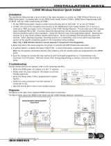
Installing the Recessed Transmitter and battery assembly
1. Using a 5/8” drill bit, drill a hole at least 4 1/4” deep in the frame at the desired location.
2. Insert the transmitter housing into the hole and trace around the edge of the ange with a pencil.
3. Remove the transmitter housing and using a standard wood chisel, score the edges of the outline and then
remove the material from the center to a depth of 1/8”.
4. Insert the transmitter and battery assembly with the reed switch orientated for the gap distance required. See
Magnet Gap Distance.
5. Install the face plate on the front of the transmitter housing and secure with the included screws. Install the
battery before nal installation.
Installing the Magnet
1. Using a 5/8” drill bit, drill a hole at least 3/4” deep in the frame at the desired location.
2. Insert the magnet into the hole and using a hammer, tap into place.
Figure 1: Installing the Recessed Contact

Digital Monitoring Products 1131 Installation Guide
2
1131 Installation Guide Digital Monitoring Products
3
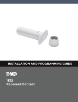
Magnet Gap Distance
The magnet gap is determined by the type of door or window and the orientation of the transmitter and battery
assembly in the housing. The reed switch is designed offset to one side to allow two gap distance options. By
installing with the reed switch toward the door opening, a 3/4 inch gap is allowed. By installing with the reed
switch away from the door opening, a 3/8 inch gap is allowed. The example provided shows a left hand door
installation. The gap distance for a sliding door application is 3/4 inch regardless of the reed switch orientation.
Installing or Replacing the Battery
Observe polarity when installing the battery. The negative end of the battery faces the transmitter printed circuit
board. Use only 3.0V lithium batteries, DMP Model CR12600SE, or the equivalent battery from a local retail outlet.
Note: When setting up a wireless system, it is recommended to program zones and connect the receiver before
installing batteries in the transmitters.
1. If installed, remove the transmitter housing face plate.
2. Pull the transmitter and battery assembly from the housing. Gently pull by gripping the antenna and end of
the printed circuit board with your ngers.
3. If replacing the battery, remove the old battery and dispose of it properly.
4. Place the 3.0V lithium battery in the holder as shown in Figure 3 with the negative end of the battery facing
the transmitter printed circuit board and hold in place.
5. Slide the transmitter and battery assembly into the transmitter housing.
4. Install the face plate on the transmitter housing.
Caution: Risk of re, explosion, and burns. Do not recharge, disassemble, heat above 212°F (100°C), or
incinerate. Properly dispose of unused batteries.
Figure 3: Replacing the Battery
Reed Switch
Figure 2: Left Hand Door Gap Distance

LT-0976 © 2008 Digital Monitoring Products, Inc.
800-641-4282
www.dmp.com
Made in the USA
INTRUSION • FIRE • AC CE SS • N ET WO RK S
2500 North Part ne rs hi p Bo ul ev ar d
Springfield, Missouri 65803-8877
8095
Battery Life Expectancy
Typical battery life expectancy for DMP Model 1131 wireless transmitters is 5 years. DMP wireless equipment uses
two-way communication to extend battery life.
The following situations can reduce battery life expectancy:
• If a receiver is unplugged or not installed.
Note: Transmitters continue to send supervision messages until a receiver returns an acknowledgement.
After an hour the transmitter only attempts a supervision message every 60 minutes.
• Frequent transmissions, such as a door that is opened and closed continuously.
• When installed in extreme hot or cold environments.
The following situation can extend battery life expectancy:
• Extend transmitter supervision time in panel programming.
• Infrequent transmission trips, such as a window that is rarely opened or closed.
FCC Information
This device complies with Part 15 of the FCC Rules. Operation is subject to the following two conditions:
(1) This device may not cause harmful interference, and
(2) this device must accept any interference received, including interference that may cause undesired operation.
The antenna used for this transmitter must be installed to provide a separation distance of at least 20 cm from all
persons. It must not be co-located or operated in conjunction with any other antenna or transmitter.
Changes or modications made by the user and not expressly approved by the party responsible for compliance could
void the user’s authority to operate the equipment.
NOTE: This equipment has been tested and found to comply with the limits for a Class B digital device, pursuant
to part 15 of the FCC Rules. These limits are designed to provide reasonable protection against harmful
interference in a residential installation. This equipment generates, uses and can radiate radio frequency
energy and, if not installed and used in accordance with the instructions, may cause harmful interference
to radio communications. However, there is no guarantee that interference will not occur in a particular
installation. If this equipment does cause harmful interference to radio or television reception, which
can be determined by turning the equipment off and on, the user is encouraged to try to correct the
interference by one or more of the following measures:
- Reorient or relocate the receiving antenna.
- Increase the separation between the equipment and receiver.
- Connect the equipment into an outlet on a circuit different from that to which the receiver is connected.
- Consult the dealer or an experienced radio/TV technician for help.
Specications
Battery
Life Expectancy 5 years (normal operation)
Type 3.0V lithium CR12600SE
See Battery Life Expectancy for full details.
Frequency Range: 903-927 MHz
Dimensions
Housing 4.175” L x .55” D
Housing Flange 1.7” H x .80” W x .06” D
Magnet Housing 0.7” L x 0.55” D x 0.65” H
Color White
Housing Material Flame retardant ABS
Patents
U.S. Patent No. 7,239,236
Listings and Approvals
FCC Part 15 Registration ID: CCKPC0109
IC Registration ID: 5251A-PC0109
/