Page is loading ...

Instruction Manual
2100-xxx
CENTERLINE 2100 Low Voltage
Motor Control Centers

Important User Information
Solid state equipment has operational characteristics differing from those of electromechanical equipment. Safety Guidelines
for the Application, Installation and Maintenance of Solid State Controls (publication SGI-1.1
available from your local
Rockwell Automation sales office or online at http://literature.rockwellautomation.com
) describes some important differences
between solid state equipment and hard-wired electromechanical devices. Because of this difference, and also because of the
wide variety of uses for solid state equipment, all persons responsible for applying this equipment must satisfy themselves
that each intended application of this equipment is acceptable.
In no event will Rockwell Automation, Inc. be responsible or liable for indirect or consequential damages resulting from the
use or application of this equipment.
The examples and diagrams in this manual are included solely for illustrative purposes. Because of the many variables and
requirements associated with any particular installation, Rockwell Automation, Inc. cannot assume responsibility or liability
for actual use based on the examples and diagrams.
No patent liability is assumed by Rockwell Automation, Inc. with respect to use of information, circuits, equipment, or
software described in this manual.
Reproduction of the contents of this manual, in whole or in part, without written permission of Rockwell Automation, Inc., is
prohibited.
Throughout this manual, when necessary, we use notes to make you aware of safety considerations.
CENTERLINE, CENTERLINE 2100, ArcShield, Allen-Bradley, Rockwell Automation, and TechConnect are trademarks of Rockwell Automation, Inc.
Trademarks not belonging to Rockwell Automation are property of their respective companies.
WARNING
Identifies information about practices or circumstances that can cause an explosion in a
hazardous environment, which may lead to personal injury or death, property damage, or
economic loss.
IMPORTANT
Identifies information that is critical for successful application and understanding of the product.
ATTENTION
Identifies information about practices or circumstances that can lead to personal injury or death,
property damage, or economic loss. Attentions help you identify a hazard, avoid a hazard, and
recognize the consequence
SHOCK HAZARD
Labels may be on or inside the equipment, for example, a drive or motor, to alert people that
dangerous voltage may be present.
BURN HAZARD
Labels may be on or inside the equipment, for example, a drive or motor, to alert people that
surfaces may reach dangerous temperatures.

3Publication 2100-IN012C-EN-P - April 2009 3
Summary of Changes
The information below summarizes the changes to this manual since
the last printing.
To help you find new and updated information in this release of the
manual, we have included change bars as shown to the right of this
paragraph.
Topic Page
Addition of ArcShield Throughout document
Updated tech support contact information Throughout document
Updated product dimensions 26
Updated seismic information 37
Addition of temperature measurement
techniques for preventative maintenance
95

4 Publication 2100-IN012C-EN-P - April 2009
Summary of Changes
Notes:

5Publication 2100-IN012C-EN-P - April 2009 5
Table of Contents
Preface
Additional Resources. . . . . . . . . . . . . . . . . . . . . . . . . . . . . . . 9
Purchased Components and Additional Instruction Sheets. . . 10
Chapter 1
General Information
General Description . . . . . . . . . . . . . . . . . . . . . . . . . . . . . . 11
Nameplate Data . . . . . . . . . . . . . . . . . . . . . . . . . . . . . . . . . 13
MCC Sequence Numbering . . . . . . . . . . . . . . . . . . . . . . . . . 14
UL/CSA Marking . . . . . . . . . . . . . . . . . . . . . . . . . . . . . . . . . 15
Short-circuit Rating Label. . . . . . . . . . . . . . . . . . . . . . . . . . . 16
Series Number and Series ID as Manufactured in the
United States. . . . . . . . . . . . . . . . . . . . . . . . . . . . . . . . . . . . 17
Series Lettering - Units and Sections. . . . . . . . . . . . . . . . . . . 20
Receiving, Handling and Storage . . . . . . . . . . . . . . . . . . . . . 22
Receiving. . . . . . . . . . . . . . . . . . . . . . . . . . . . . . . . . . . . 22
Handling . . . . . . . . . . . . . . . . . . . . . . . . . . . . . . . . . . . . 23
Storage and Operation . . . . . . . . . . . . . . . . . . . . . . . . . . 24
Chapter 2
Installation Procedures
Location Planning . . . . . . . . . . . . . . . . . . . . . . . . . . . . . . . . 25
Height Considerations . . . . . . . . . . . . . . . . . . . . . . . . . . . . . 25
Securing an MCC . . . . . . . . . . . . . . . . . . . . . . . . . . . . . . . . 26
Seismic Requirements . . . . . . . . . . . . . . . . . . . . . . . . . . . . . 37
Joining & Splicing New MCCs . . . . . . . . . . . . . . . . . . . . . . . 38
Joining & Splicing Existing MCCs . . . . . . . . . . . . . . . . . . . . . 38
Installing and Joining Pull Boxes . . . . . . . . . . . . . . . . . . . . . 38
Joining and Splicing NEMA Type 12 MCCs . . . . . . . . . . . . . . 39
Joining & Splicing NEMA Type 3R and Type 4 MCCs . . . . . . 39
Bus Torque Specifications . . . . . . . . . . . . . . . . . . . . . . . . . . 40
Chapter 3
Installing Conduit and Cable
Installing Conduit . . . . . . . . . . . . . . . . . . . . . . . . . . . . . . . . 41
Bottom Entry Conduit . . . . . . . . . . . . . . . . . . . . . . . . . . 41
Top Entry Conduit . . . . . . . . . . . . . . . . . . . . . . . . . . . . . 41
Installing Cable . . . . . . . . . . . . . . . . . . . . . . . . . . . . . . . . . . 42
Lugs . . . . . . . . . . . . . . . . . . . . . . . . . . . . . . . . . . . . . . . 42
Incoming Line Compartment . . . . . . . . . . . . . . . . . . . . . 43
Main Disconnect . . . . . . . . . . . . . . . . . . . . . . . . . . . . . . 43
Cable Bracing . . . . . . . . . . . . . . . . . . . . . . . . . . . . . . . . 43
Incoming Line Brace . . . . . . . . . . . . . . . . . . . . . . . . . . . 45
Chapter 4
Installing and Removing Plug-in
Units
Installing Plug-in Units . . . . . . . . . . . . . . . . . . . . . . . . . . . . 47
Remove a Plug-in Unit with a Vertical Operating Handle
from a Section . . . . . . . . . . . . . . . . . . . . . . . . . . . . . . . . . . 48

6 Publication 2100-IN012C-EN-P - April 2009
Table of Contents
Remove a Plug-in Unit with a Horizontal Operating Handle
from a Section . . . . . . . . . . . . . . . . . . . . . . . . . . . . . . . . . . 53
Remove the Support Pan. . . . . . . . . . . . . . . . . . . . . . . . . . . 57
Chapter 5
Arc Flash Protection Marking as
Required by the National
Electrical Code
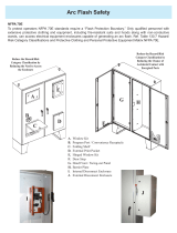
Flash Protection Marking Requirement . . . . . . . . . . . . . . . . . 59
110.16 Flash Protection . . . . . . . . . . . . . . . . . . . . . . . . . 59
Arc Flash Marking Clarification . . . . . . . . . . . . . . . . . . . . . . 60
Rockwell Automation Services . . . . . . . . . . . . . . . . . . . . . . . 60
Chapter 6
Operator Handle and Unit
Interlock
Defeating the Unit Door Interlock . . . . . . . . . . . . . . . . . . . . 61
Open the Door when the Operating Handle is in the
ON/I Position . . . . . . . . . . . . . . . . . . . . . . . . . . . . . . . . 61
Defeating the Unit Interlock Lever . . . . . . . . . . . . . . . . . . . . 63
Energize a Unit with the Unit Door Open . . . . . . . . . . . . 63
Locking Provisions . . . . . . . . . . . . . . . . . . . . . . . . . . . . . . . 64
Lock Vertical Operating Handles in the OFF/O Position . 64
Lock Horizontal Operating Handles in the OFF/O
Position. . . . . . . . . . . . . . . . . . . . . . . . . . . . . . . . . . . . . 65
Lock Units with Operating Handles in the ON/I Position . 66
Unit Interlocks. . . . . . . . . . . . . . . . . . . . . . . . . . . . . . . . 68
Chapter 7
Final Check List Before Energizing
Introduction . . . . . . . . . . . . . . . . . . . . . . . . . . . . . . . . . . . . 73
Pre-Energizing Check Procedure . . . . . . . . . . . . . . . . . . . . . 73
Perform the Pre-energizing Check Procedure . . . . . . . . . . . . 74
Chapter 8
Energizing the Equipment
Energize the Equipment . . . . . . . . . . . . . . . . . . . . . . . . . . . 89
Chapter 9
Maintenance
Maintain the MCC . . . . . . . . . . . . . . . . . . . . . . . . . . . . . . . . 91
Disconnect the Switch and Contact Lubrication . . . . . . . . . . 94
Use Thermal Infrared or Other Temperature Measurement
Techniques for Preventive Maintenance . . . . . . . . . . . . . . . . 95
Inspect the Units for Signs of Overheating . . . . . . . . . . . 96
Chapter 10
Maintenance After Fault Condition
Maintain the MCC After a Fault Condition . . . . . . . . . . . . . . 99
Chapter 11
Renewal Parts
Order Information. . . . . . . . . . . . . . . . . . . . . . . . . . . . . . . 101

Publication 2100-IN012C-EN-P - April 2009 7
Table of Contents
Chapter 12
Parts Illustrations
Typical Section Construction . . . . . . . . . . . . . . . . . . . . . . . 103
Typical Construction of a Unit with a Vertical Operating
Handle . . . . . . . . . . . . . . . . . . . . . . . . . . . . . . . . . . . . . . . 104
Typical Construction of a Half Space Factor Unit with a
Horizontal Operating Handle and Door Mounted Pilot
Devices . . . . . . . . . . . . . . . . . . . . . . . . . . . . . . . . . . . . . . 105
Typical Construction of a Unit with a Horizontal Operating
Handle . . . . . . . . . . . . . . . . . . . . . . . . . . . . . . . . . . . . . . . 106
Index

8 Publication 2100-IN012C-EN-P - April 2009
Table of Contents

9Publication 2100-IN012C-EN-P - April 2009 9
Preface
Additional Resources
The following publications supplement this manual. For more
information and further reference, please use these available
publications.
You can view or download publications at
http://literature.rockwellautomation.com
. To order paper copies of
technical documents, contact your local Rockwell Automation
distributor or sales representative.
Publication Name Publication No.
Arc-Flash Resistant Low Voltage Motor Control Center Designs
White Paper
2100-AP003
Power Factor Correction Capacitors for Bulletin 2100 MCC
Starter Units Application Techniques
2100-AT001
CENTERLINE 2100 Motor Control Centers Joining and Splicing
Vertical Sections Instructions
2100-IN010
CENTERLINE 2100 Motor Control Centers (MCC) Units with
Vertical Operating Handles Installation Instructions
2100-IN014
CENTERLINE Motor Control Centers NEMA Type 12 Sealing
Instructions
2100-IN037
Receiving, Handling, and Storing Motor Control Centers 2100-IN040
MCC Instantaneous Trip Motor Circuit Protectors (MCP) in
Combination NEMA Starter, Soft Starter (SMC), and Variable
Frequency AC Drive Units Technical Data
2100-TD001
MCC Inverse Time Circuit Breakers in Combination NEMA
Starter, Soft Starter (SMC), and Variable Frequency AC Drive
Units Technical Data
2100-TD002
CENTERLINE Motor Control Centers Power Fuses Product Data 2100-TD003
DeviceNet Motor Control Centers (MCC) Technical Data 2100-TD019
CENTERLINE 2100 Motor Control Center End Closing Plates
Installation Instructions
2100-IN069
CENTERLINE 2100 Motor Control Center (MCC) Units with
Horizontal Operating Handles Installation Instructions
2100-IN060
CENTERLINE Motor Control Centers Mains and Incoming Lines
Reference Document Update
2100-TD018
CENTERLINE Motor Control Centers Installing a Pull Box on a
Bulletin 2100 Vertical Section Instructions
2100-IN029
Safety Guidelines for the Application, Installation, and
Maintenance of Solid-state Control
SGI-IN001

10 Publication 2100-IN012C-EN-P - April 2009
Preface
The documents in the following table are referenced in this document
and can be obtained from their respective organizations.
Purchased Components and
Additional Instruction
Sheets
When equipment such as transformers, metering, PLCs, or drives are
supplied with the motor control center (MCC), specific manuals and
data sheets are also supplied. These documents should be read and
understood before installing and operating the MCC. Refer to the unit
locations of these devices for their manuals and/or data sheets.
Resource Website
National Electrical Manufacturer’s Association (NEMA)
• NEMA ICS 1-2000 Industrial Control and Systems: General
Requirements
• NEMA ICS 2.3-1995, Instructions for Handling, Operation and
Maintenance of Motor Control Centers Rated Not More Than
600V
www.nema.org
National Fire Protection Association (NFPA)
• NFPA 70 - National Electrical Code
• NFPA 70A - Recommended Practice for Electrical Equipment
Maintenance
• NFPA 70E - Standard for Electrical Safety in the Workplace
www.nfpa.org
Institute of Electrical and Electronic Engineers (IEEE)
IEEE standard C37.20.7 - IEEE Guide for Testing Metal-Enclosed
Switchgear Rated Up to 38 kV for Internal Arcing Faults
www.ieee.org

11Publication 2100-IN012C-EN-P - April 2009 11
Chapter
1
General Information
General Description
Allen-Bradley CENTERLINE Motor Control Centers (MCCs) consist of
one or more vertical sections containing electromagnetic and/or solid
state control devices that are prewired and tested within modular
(plug-in) or frame mounted (hard-wired) units.
CENTERLINE MCCs are designed in standard widths of 20 in.
(508 mm), 25 in. (635 mm), 30 in. (762 mm), 35 in. (789 mm), and
40 in. (1016 mm). The standard front-mounted depths of an MCC are
15 in. (381 mm) and 20 in. (508 mm), in addition back-to-back
mounted depths of 30 in. (762 mm) and 40 in. (1016 mm) are also
offered. The standard height of an MCC is 90 in. (2286 mm). A 70.5 in.
(1791 mm) high section is also available. All MCC sections are
supplied with top and bottom horizontal wireways. Sections which
are designed to accommodate plug-in units include a vertical
wireway. Each 90 in. (2286 mm) vertical section can accommodate up
to 6.0 space factors or 78 in. (1981 mm) for units.
Units (buckets) are designed in increments of 0.5 space factors. Each
0.5 space factor is approximately 6.5 in. (165.1 mm) high. Units are
designed as either removable (plug-in) or frame-mounted
(non-plug-in).
Individual units house a wide variety of power and logic devices.
Plug-in units are mounted on unit support pans within the section.
Stab assemblies located on the back of the unit plug onto the vertical
bus. A mechanical interlock prevents the unit door from being opened
when the disconnect is not in the OFF position. An additional
mechanical interlock prevents the unit from being plugged-in or
unplugged when the disconnect is not in the OFF position.
Line power is distributed throughout the MCC via an isolated bus
work structure. The main horizontal bus is located in the center of
each section. Standard, center-fed, 300 A rated vertical bus supplies
power to the individual units above and below the horizontal bus for
an effective 600 A capacity, allowing virtually unrestricted unit
arrangement. An optional 600 A vertical bus provides 1200 A effective
rating.

12 Publication 2100-IN012C-EN-P - April 2009
Chapter 1 General Information
The CENTERLINE MCC is also available with ArcShield. ArcShield
includes arc resistant features which are intended to help provide
enhanced protection to you during internal arcing faults (when
compared to MCCs which are only designed to meet UL 845
requirements). Arcing faults can be caused, for example, by accidental
touching, closing into faulted lines, or loose connections. Depending
on the application, ArcShield can provide up to Type 2 accessibility
per IEEE standard C37.20.7, which helps protect you when you are
located at the front, sides, and rear of the enclosure in the unlikely
event of an arcing fault.
A label on the MCC with ArcShield provides information in regard to
the accessibility level and arc fault ratings.
For more information about accessibility levels, performance, and
testing requirements, refer to IEEE standard C37.20.7, IEEE Guide for
Testing Metal-Enclosed Switchgear Rated up to 38 kV for Internal
Arcing Faults.
ArcShield provides a reinforced MCC structure and arc-containment
latches on all doors. To help protect you during an arc-fault,
arc-containment latches, when closed and latched properly, allow
pressure relief and help keep the doors from unlatching or detaching
from the structure.

Publication 2100-IN012C-EN-P - April 2009 13
General Information Chapter 1
Nameplate Data
Each MCC section has a nameplate located on the enclosure or
vertical wireway door. The nameplate includes:
• catalog number/serial number.
• series letter of section.
• bus bar voltage and current rating.
• section number.
• UL and cUL certification marking.
• UL registration number.
• enclosure type.
Section Nameplate
Each plug-in and frame mounted unit also has an identification label.
The unit label is located on the interior of the bottom plate of plug-in
units or on the interior right-hand side plate of the frame mounted
units. The unit label for each plug-in or frame mounted unit includes:
• catalog number/serial number.
• series letter of the unit.
• voltage rating.
• unit location.
• UL and cUL certification marking.
• device type and size.
Unit Label
The catalog number or serial number and series letter are required to
properly identify the equipment to sales or factory personnel.
Section Number
UL and cUL Certification Marking
Catalog Number/Serial Number
Series Letter of Section
Bus Bar Voltage
and Current Rating
UL Registration Number
Enclosure Type
cUL Certification Marking
Catalog Number / Serial Number
Unit Location
Device Type and Size
Voltage Rating
Series Letter of Unit

14 Publication 2100-IN012C-EN-P - April 2009
Chapter 1 General Information
MCC Sequence Numbering
CENTERLINE MCCs are designed so functionality is not affected by the
section installation order, for example, vertical section-numbering
sequence order.
All MCC sections carry a serial plate, which identifies vertical section
sequence numbering. For example, MCC section 1 of 1, 1 of 5, and so
on.
Section Nameplate
Sections are numbered to match factory-supplied MCC elevation
drawings. Numbering each section helps installers and users easily
identify MCCs, sections, and units. If there are questions about section
numbering during field installation, inspection, or operation, the
following information can provide guidance on equipment
acceptability, listing, and certification.
CENTERLINE MCC sections can be installed or added as follows:
• In non-sequential order
• Addition of a single section (add-on section)
• Addition of multiple sections (add-on lineup of sections)
• Addition of single section or multiple section between MCC
sections
If sections are added to an existing lineup and not installed in
sequential order, the installation should not be considered a
misapplication or in conflict with Underwriter Laboratories (UL) listing
and Canadian Standards Association (CSA) certification.
The paramount criteria for additions of sections to existing MCCs is
matching the horizontal bus electrical and ingress protection
(enclosure type) ratings for the total MCC line up. For example, the
voltage, current rating, short circuit withstand, and NEMA enclosure
type (IP rating) for all sections must match.
Identifies Vertical Section
Sequence Numbering

Publication 2100-IN012C-EN-P - April 2009 15
General Information Chapter 1
Non-sequential numbering may not create a functional or
listing/certification issue. However, MCCs should be installed in
sequential order. Installing MCCs in sequential order helps ensure
proper installation and ensures that factory-supplied documentation
matches the equipment.
You can rearrange MCC sections. However, if a section that uses a
right-hand side sheet with integral, internal mounting flanges is
located on the outside of a lineup, an additional closing kit plate is
required. Refer to CENTERLINE 2100 Motor Control Center End
Closing Plates Installation Instructions, publication 2100-IN069
. MCCs
that contain contain arc resistant features cannot use a section with
integral mounting flanges on the outside of a lineup.
UL/CSA Marking
CENTERLINE MCCs are listed by Underwriter’s Laboratories, Inc. (UL),
Standard for Safety UL 845, and certified by the Canadian Standards
Associate (CSA), Standard C22-2, No. 14.
Due to standards harmonization, a MCC may also carry the cUL
designation. cUL is comparable to CSA certification.
Vertical sections and units are labeled independently. It is possible to
have combinations of labeled and non-labeled sections and units in
the same MCC.
Vertical sections and structure options that are UL listed and CSA/cUL
certified are marked accordingly. All components in a UL or CSA listed
section must be UL listed and cUL/CSA certified. The UL and/or
CSA/cUL designation is an integral part of the section nameplate as
shown on page 14
.
Units and unit options that are UL listed and CSA/cUL certified are
marked accordingly. All options and components in a UL and/or
cUL/CSA listed unit must be UL listed or recognized and/or cUL/CSA
certified. The UL designation is located on the interior of the bottom
plate of plug-in units or on the interior right-hand side plate of frame
mounted units.
UL Label Designation for Units

16 Publication 2100-IN012C-EN-P - April 2009
Chapter 1 General Information
Short-circuit Rating Label
MCC vertical sections that are UL listed and/or CSA/cUL certified will
carry a short-circuit rating label. The short-circuit rating label for a
vertical section is located on the inside of the vertical wireway door of
standard sections or on the interior right-hand side plate of a section
that contains a unit that occupies the full section and does not contain
a vertical wireway.
Short Circuit Label for Sections
MCC units that are UL listed and/or CSA/cUL certified will carry a
short-circuit rating label located on the bottom plate of plug-in units
or on interior right-hand side plate of frame mounted units.
Short Circuit Label for Units

Publication 2100-IN012C-EN-P - April 2009 17
General Information Chapter 1
Series Number and Series
ID as Manufactured in the
United States
ATTENTION
Read tables through before adding new sections or units to an
existing CENTERLINE MCC.
Sections
Series
Letter
Scope Description of Change Date
Implemented in
the U.S.
A
(1)
— Original design
February 1971
B
(1)
All Changed terminal blocks
November 1976
C
(1)
All Elimination of external mounting channels
June 1979
D
(1)
All Reverse fed 2192 and 2193
April 1981
E
(1)
All Redesign gasketing
October 1982
F
(1)
All Modified top horizontal wireway pan to accept units with handle interlock in topmost space
factor
October 1983
G
(1)
42K 42 k bracing-incorporates new bus support & cover
January 1985
G
(1)
65K 65 k bracing-incorporates new bus support & cover
July 1985
H All New hinge design January 1986
J All Changed handle, operating mechanism, and circuit breaker to Cutler-Hammer series C, 150 A,
250 A, 400 A frame
October 1986
K All Changed to new unit grounding system May 1990
L All Changed to new 600 A...1200 A circuit breaker operating mechanism February 1996
M All Changed to serpentine DeviceNet cabling system May 2001
(1)
Replacement and renewal parts are no longer supported. For more information, contact Rockwell Automation LV MCC Technical Support at 1.440.646.5800 and follow the
prompts to Allen-Bradley>Low Voltage Motor Control Centers>Post Shipment Support.
2100 Units
Series
Letter
Scope Description of Change Date Implemented
in U.S.
A
(1)
— Original design
February 1971
B
(1)
All sizes Changed terminal blocks
November 1976
C
(1)
All sizes Changed handle mechanism to Cutler-Hammer MCPs
June 1979
D
(1)
Size 5 Changed from ITE to A-B 400A disconnect
April 1981
E
(1)
All sizes Changed from Bulletin 709 series K starters to Bulletin 500 line starters
April 1981

18 Publication 2100-IN012C-EN-P - April 2009
Chapter 1 General Information
F
(1)
All sizes Redesign of gasketing, wraparound and unit support pan for Bulletin 700 line
October 1982
G
(1)
All sizes Redesign of gasketing, wraparound and unit support pan for Bulletin 500 line
October 1982
H
(1)
All sizes Changed to new door, circuit breaker mechanism and control station
April 1984
J
(1)
Size 5 Changed to Bulletin 500 series L October 1984
Size 3 Changed to new PCP 100A disconnect December 1988
Size 6 Changed to Bulletin 500 series B starters October 1988
K
Size 1-5 CB
units and size
1-2 disc units
Changed handle, operating mechanism and circuit breaker to Cutler-Hammer series
C, 150 A, 250 A, 400 A frame October 1986
L
21A through
54A
Changed to Bulletin 100 line contactors in 21 A, 30 A, 45 A SMC units and original
design 24 A, 35 A, 54 A SMC units
November 1989
M
All sizes Changed to new unit grounding system and 600 A, 800 A, 1200 A bolted pressure
switch
May 1990
N
All sizes Changed to PCP 200 A and 400 A disconnect, rerated vacuum Bulletin 2112 and
2113 and new pilot device offerings
January 1993
P
0.5 SF CB units
2103L, 2113,
2193
External auxiliary on circuit breakers
April 1994
Q
All sizes and
ratings
New disconnect external auxiliary contacts and new 600 A...1200 A circuit breaker
operating mechanism
May 1996
R
SMC units Redesign and upgrade of ratings for 24 A...500 A SMC-2 and SMC-PLUS units.
Original design of SMC Dialog Plus units
August 1997
1200A 2193 Redesign of 1200A, 2193F and 2193M units November 1997
800A 2193 Changed circuit breakers to MDL Frame November 1998
225A 2193F Changed circuit breakers from J Frame to F Frame October 1999
T
2000A 2193 Changed to flange mounted operating handle November 2000
All sizes Changed the Bulletin 800MR and Bulletin 800T-PS pilot devices to Bulletin 800Es November 2000
All 1.5 space
factor units
Changed unit bottom plate
November 2000
U
All except
2100-SD1
Changed to new Bulletin 1497 control circuit transformer
July 2001
2100-SD1 Changed smoke detector head and base components November 2001
2100 Units
Series
Letter
Scope Description of Change Date Implemented
in U.S.

Publication 2100-IN012C-EN-P - April 2009 19
General Information Chapter 1
V
2162Q, 2163Q,
2164Q, 2165Q
Redesign of 240-480V PowerFlex 70 and release of 600V PowerFlex 70
April 2002
2162R, 2163R,
2164R, 2165R
Original release of PowerFlex 700
July 2002
2154H, 2155H Original release of SMC-3 November 2002
2154J, 2155J Original release of SMC Flex April 2004
2112, size 3, 4
and 5
Redesign to reduced space factor with Class J fuse clip
April 2004
2162T, 2163T Original release of PowerFlex 40 September 2004
2107, 2113,
size 3
Reduced space factor
April 2005
X
2162Q, 2163Q Reduced space factor, changed CCT with integral fuses April 2005
All sizes 800F pilot devices August 2005
Y
2154J, 2155J,
108 A and 135
A
Redesign to change units from frame mounted to plug-in
March 2006
(1)
Replacement and renewal parts are no longer supported. For more information contact, Rockwell Automation LV MCC Technical Support at 1.440.646.5800 and follow the
prompts to Allen-Bradley>Low Voltage Motor Control Centers>Post Shipment Support.
2100 Units
Series
Letter
Scope Description of Change Date Implemented
in U.S.
2400 Units
Series
Letter
Scope Description of Change Date
Implemented in
U.S.
A — Original design June 1990
B 18A, 24A, 30A Changed to series B, Bulletin 194R, 30 A disconnect March 1992
C 18A, 24A, 30A Changed to three Bulletin 800E pilot devices on 0.5 space factor units July 1992
D
All sizes New disconnect external auxiliary contacts and new 600 A...1200 A circuit breaker
operating mechanism
February 1996
16A-85A Original design of units with a Bulletin 100-C contactor September 1999

20 Publication 2100-IN012C-EN-P - April 2009
Chapter 1 General Information
Series Lettering - Units and
Sections
When using sections in conjunction with units of different series
letters, consult the table below.
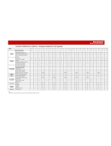
MCC Modifications for Unit and Structure Compatibility
If Mounted in
this Type of
Section
(1)
,
(2)
Plug-in Units No
Additional
Parts
Required
Requires
Style 1 Unit
Support Pan
Requires
Style 3 Unit
Support
Pan
Requires
Style 3 Unit
Support Pan
w/ Bushing
Requires
Alternate Top
Horizontal
Wireway Pan
Requires
Door
Gasketing
Kit
Requires
Retrofit
Kit
(3)
Requires
Ground
Bus Kit
Space
Factor
Series — 2100H-UAJ1 2100H-UA1
2100H-UJ1
2100H-USPA1
2100H-USPJ1
2100H-NA4A1
2100H-NA4J1
2100H-NA4A2
2100H-NA4J2
2100-GJ10 2100H-R1
2100H-R2
2100H-GS1
NEMA Type 1
Series A...D
(4)
1.0 or
larger
A-E
(4)
——— ————
F-L
(4)
— ——
(5)
———
M or
later
(6)
— ——
(5)
——
NEMA Type 1
Series E...J
(4)
0.5
(2)
N or
later
——— ——
1.0 or
larger
A-E
(4)
—— ————
(8)
F-L
(4)
——— ————
M or
later
(6)
——— — — ——
NEMA Type 1
Series K or
later
0.5
(2)
N or
later
——— ————
1.0 or
larger
A-L
(4)
—— ————
(8)
M or
later
——— ————
NEMA Type 1
w/gasket or
Type 12
Series A...D
1.0 or
larger
A-E
(4)
——— ————
F-L
(4)
— ——
(5)
——
M or
later
— ——
(5)
—
NEMA Type 1
w/gasket or
Type 12
Series E...J
(7)
0.5
(2)
N or
later
——— ——
1.0 or
larger
A-E
(4)
—— ————
(8)
F-L
(4)
——— ————
M or
later
——— — — ——
NEMA Type 1
w/gasket or
Type 12
Series K or
later
0.5
(2)
N or
later
——— ————
1.0 or
larger
A-L
(4)
—— ————
(8)
M or
later
——— ————
/