Page is loading ...

1114 Wireless Four-Zone Expander
Description
The 1114 Wireless Four-Zone Expander increases the number of reporting zones available on DMP Command
Processor™ Panels. Use the four zones with burglary or other non-powered devices. The 1114 is designed to operate
on one CR123A battery or connect to an optional 12 VDC power supply.
The 1114 operates with the XR500 or XR100 Series Command Processor™ panels version 119 using the 1100X Wireless
Receiver version 104 or with the XRSuper6, XR20, and XR40 Command Processor™ Panels version 304 using the 1100D
Wireless Receiver version 104.
What is included
The 1114 includes the following:
• One 1114 Wireless Four-Zone Expander
• One 3.0V Lithium CR123A battery
• Hardware pack with 470k EOL Resistors
• Serial number label
Optional items available:
• One Model 376 DC Power Supply
• One Model 378 Barrel Connector with Cord
Serial Number
For your convenience, an additional pre-printed serial number label is included. Prior to installing the zone
expander, record the serial number or place the pre-printed serial number label on the panel programming sheet.
This number is required during programming.
Programming the 1114 in the Panel
Program the 1114 Wireless Four-Zone Expander as a zone in Zone Information. At the Serial Number: prompt, enter
the eight-digit serial number. Continue to program the zone as directed in the panel programming guide. Refer to
the XR500 Series Programming Guide (LT-0679), the XR100 Series Programming Guide (LT-0896), or the XRSuper6/
XR20/XR40 Programming Guide (LT-0305) as needed.
Note: When a receiver is installed, powered down and powered up, the panel is reset, or programming is complete,
the supervision time is reset. If the receiver has been powered down for more than one hour, the 1114 may take
up to an additional hour to send a supervision message unless tripped, tampered, or powered up. This operation
extends battery life. A missing message may display on the keypad until the supervision message is sent.
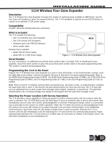
Selecting the Proper Location (LED Survey Operation)
The 1114 provides a survey capability to allow one person to conrm communication with the receiver while the
cover is removed. The 1114 PCB Red Survey LED (See Figure 2) turns on whenever data is sent to the receiver then
immediately turns off when the receiver acknowledgement is received. Pressing the tamper switch is a convenient
way to send data to the receiver to conrm operation. When the 1114 does not receive an acknowledgement from
the receiver the survey LED remains on for about 8 seconds to let you know communication is not established.
Communication is also faulty when the LED ashes multiple times in quick succession. Relocate the 1114 or
receiver until the LED immediately turns off indicating the 1114 and receiver are communicating properly. Proper
communication between the 1114 and receiver is veried when for each press or release of the tamper switch, the
LED blinks immediately on and immediately off.
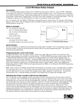
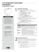
Squeeze to
Remove Cover
Squeeze to
Remove Cover
Power Supply
Plug Location
Figure 1: 1114 Wireless Four-Zone Expander
INSTALLATION GUIDE
www.BevanSecurity.com

Digital Monitoring Products 1114 Installation Guide
2
1114 Installation Guide Digital Monitoring Products
3
Installing the 1114
Mount the 1114 on a at surface such as a wall or single-gang box. When using the optional Model 376 plug-in power
supply, mount the 1114 near a wall outlet. See Figure 2 for mounting hole locations.
Red LED
(Survey)
Tamper
Switch
Mounting Holes
+
3.0V
Lithium
B
attery
—
Internal
Antenna
Location
EXT
BAT
Power Supply
Adapter Plug
Housing
Figure 2: 1114 Four-Zone Expander PCB
1114 Zone Wiring
It is recommended to locate zone devices within 100 feet of the
1114 zone expander. Use 22 or 18 AWG wire to complete the
connections between the 1114 zone expander Zones 1 through
4 and each eld device. Each zone terminates with one of the
included 470k EOL resistors as shown.
Powering the 1114
The 1114 can be powered by:
• CR123A 3.0 VDC battery
• Model 376 plug-in power supply
• 12 VDC Power Supply
Note: When setting up a wireless system, it is recommended to program zones and connect the receiver before
installing batteries in the 1114 or connecting the optional power supply.
Battery Power
Observe polarity when installing the battery. Use only 3.0V Lithium batteries, DMP Model CR123, or the equivalent
battery from a local retail outlet. Do not connect the power supply when operating using battery power.
1. Squeeze the cover left and right sides together to remove. See Figure 1.
2. Install the supplied jumper on the two J1 pins next to BAT to enable battery operation.
Note: Battery operation is not enabled if the jumper is on the J1 pins next to EXT.
3. If replacing the battery, remove the old battery and dispose of it properly.
4. Place the 3.0V Lithium battery in the holder and press into place. See Figure 4 for Battery location.
5. Snap the cover back into place.
Caution: Properly dispose of unused batteries. Do not recharge, disassemble, heat above 212°F (100°C),
or incinerate. Risk of re, explosion, and burns.
470k EOL
Figure 3: 1114 Zone Terminals
www.BevanSecurity.com

Digital Monitoring Products 1114 Installation Guide
2
1114 Installation Guide Digital Monitoring Products
3
Battery Life Expectancy
Typical battery life expectancy for the 1114 is three years. Refer to the XR500 Series Programming Guide (LT-0679),
XR100 Series Programming Guide (LT-0896), or the XRSuper6/XR20/XR40 Programming Guide (LT-0305) as needed.
DMP wireless equipment uses two-way communication to extend battery life.
The following situation can extend battery life expectancy:
• Extend transmitter supervision time in panel programming.
The following situations can reduce battery life expectancy:
• If a receiver is unplugged or not installed.
Note: Transmitters continue to send supervision messages until a receiver returns an acknowledgement.
After an hour the transmitter only attempts a supervision message every 60 minutes.
• When installed in extreme hot or cold environments.
Optional External DC Plug-in Power Supply
When using the optional Model 376 plug-in DC power supply, mount the 1114 near a wall outlet. Do not install a
battery when operating using the plug-in power supply. The power
supply does not charge the battery.
Use the following steps to connect the plug-in power supply:
1. Squeeze the left and right cover sides together to remove. See
Figure 1.
2. Install the supplied jumper on the two J1 pins next to EXT to
enable power supply operation.
Note: Power supply operation is not enabled if the jumper is on
the J1 pins next to BAT.
3. Snap the cover back into place.
4. Plug the barrel connector into the J2 barrel jack at the side of
the 1114 cover. See Figure 4.
5. Plug the Model 376 power supply into a 110 Volt AC outlet.
Optional External 12 VDC Power Supply
The 1114 can also be powered from a 12 VDC power supply such as a DMP Model 502-12. Use DMP Model 378 barrel
connector with cord, or the equivalent 5.5 x 2.1 mm barrel connector from a local retail outlet and 22 AWG wire to
connect to the power supply. Do not install a battery when operating using the external power supply. The power
supply does not charge the battery.
Use the following steps to connect the power supply:
1. Squeeze the left and right cover sides together to remove.
See Figure 1.
2. Install the supplied jumper on the two J1 pins next to EXT to
enable power supply operation.
Note: Power supply operation is not enabled if the jumper is
on the J1 pins next to BAT.
3. Snap the cover back into place.
4. If using the Model 378, connect the Black wire with White
stripe to the J6 positive terminal on the 502-12 power supply
PCB and the Black wire to the J6 negative terminal.
5. Plug the Model 378 barrel connector into the J2 barrel jack at
the side of the 1114 cover. See Figure 4.
6. If installing a purchased 5.5 x 2.1 mm barrel connector, use 22 AWG wire to connect the positive wire to the
pin and negative wire (GND) to the ring (barrel). See Figure 5.
7. Connect the 22 AWG wire ends to the J6 DC connector on the 502-12 power supply PCB. Observe positive
and negative polarity on all connections.
8. Plug the barrel connector into the J2 barrel jack at the side of the 1114 cover. See Figure 4.
Side View
J2
Power
Supply
Battery Connectors
Barrel Jack
J1
EXT BAT
Jumper
Barrel
Connector
Figure 4: 1114 Side View
Figure 5: Power Supply Connection
www.BevanSecurity.com

LT-0705 (5/07) © 2007 Digital Monitoring Products, Inc.
I N T R U S I O N • F I R E • A C C E S S • N E T W O R K S
2 5 0 0 N o r t h P a r t n e r s h i p B o u l e v a r d
8 0 0 - 6 4 1 - 4 2 8 2
w w w . d m p . c o m
M a d e i n t h e U S A
S p r i n g e l d , M i s s o u r i 6 5 8 0 3 - 8 8 7 7
Specications
Battery
Life Expectancy 3 years
Type 3.0V Lithium CR123A
See Battery Life Expectancy for full details.
Frequency Range 903-927 MHz
Dimensions 4.65” L x 3.1” W x 1.4” H
Color White
Housing Material Flame retardant ABS
Accessories
CR123 DMP 3.0V Lithium Battery
376 DC Plug-in Power Supply
378 Barrel Connector with Cord
502-12 12 VDC Power Supply
Compatibility
The 1114 Wireless Zone Expansion Transmitter is
compatible with:
XR500 or XR100 panels version 119
1100X Wireless Receiver version 104
XRSuper6, XR20, and XR40 panels version 304
1100D Wireless Receiver version 104
Patents
Patent(s) Pending
Listings and Approvals
FCC Part 15 Registration ID CCKPC0101
IC Registration ID 5251A-PC0101
FCC Information
This device complies with Part 15 of the FCC Rules. Operation is subject to the following two conditions:
(1) This device may not cause harmful interference, and
(2) this device must accept any interference received, including interference that may cause undesired operation.
The antenna used for this transmitter must be installed to provide a separation distance of at least 20 cm (7.874 in.)
from all persons. It must not be located or operated in conjunction with any other antenna or transmitter.
Changes or modications made by the user and not expressly approved by the party responsible for compliance could
void the user’s authority to operate the equipment.
NOTE: This equipment has been tested and found to comply with the limits for a Class B digital device, pursuant
to part 15 of the FCC Rules. These limits are designed to provide reasonable protection against harmful
interference in a residential installation. This equipment generates, uses and can radiate radio frequency
energy and, if not installed and used in accordance with the instructions, may cause harmful interference
to radio communications. However, there is no guarantee that interference will not occur in a particular
installation. If this equipment does cause harmful interference to radio or television reception, which
can be determined by turning the equipment off and on, the user is encouraged to try to correct the
interference by one or more of the following measures:
- Reorient or relocate the receiving antenna.
- Increase the separation between the equipment and receiver.
- Connect the equipment into an outlet on a circuit different from that to which the receiver is connected.
- Consult the dealer or an experienced radio/TV technician for help.
www.BevanSecurity.com
/