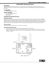
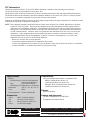
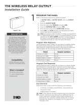
DMP Electronics 1116 is a wireless relay output that can be controlled from a DMP Command Processor™ panel. It provides a Form C (SPDT) dry relay contact rated for 1 Amp @ 30 VDC. The 1116 operates on constant minimal standby current and can be controlled from a DMP Command Processor™ panel output programmed to respond to various conditions such as armed area annunciation, ambush alarm, burglary alarm, exit timer, entry timer, schedules, or communication failure. It can operate on one CR123A battery or connect to an optional 12 VDC power supply.
DMP Electronics 1116 is a wireless relay output that can be controlled from a DMP Command Processor™ panel. It provides a Form C (SPDT) dry relay contact rated for 1 Amp @ 30 VDC. The 1116 operates on constant minimal standby current and can be controlled from a DMP Command Processor™ panel output programmed to respond to various conditions such as armed area annunciation, ambush alarm, burglary alarm, exit timer, entry timer, schedules, or communication failure. It can operate on one CR123A battery or connect to an optional 12 VDC power supply.


-
 1
1
-
 2
2
-
 3
3
-
 4
4


DMP Electronics 1116 is a wireless relay output that can be controlled from a DMP Command Processor™ panel. It provides a Form C (SPDT) dry relay contact rated for 1 Amp @ 30 VDC. The 1116 operates on constant minimal standby current and can be controlled from a DMP Command Processor™ panel output programmed to respond to various conditions such as armed area annunciation, ambush alarm, burglary alarm, exit timer, entry timer, schedules, or communication failure. It can operate on one CR123A battery or connect to an optional 12 VDC power supply.
Ask a question and I''ll find the answer in the document
Finding information in a document is now easier with AI
Related papers
-
 DMP Electronics 1116 Installation guide
-
 DMP Electronics 1114 Installation guide
-
 DMP Electronics 1131 User manual
-
 DMP Electronics 1100X Installation Note
-
 DMP Electronics 1141 Installation guide
-
 DMP Electronics 1137 User manual
-
 DMP Electronics 1100 Series Installation guide
-
 DMP Electronics 575 Installation guide
-
 DMP Electronics 575 Installation guide
-
 DMP Electronics 1116 Installation guide