Page is loading ...

InstallatIon GuIde
382 AnyNET-DMP Cable
Description
The Uplink AnyNET-DMP Network Access Module supports cellular networking technologies for backup communication.
The AnyNET-DMP Module is compatible with XR500, XR500N, or XR500E Command Processor™ panels. Use a DMP
382-6 or 382-50 cable to provide supervised communications between the AnyNET-DMP module and the XR500 Series.
Mounting the Module
Mount the AnyNET-DMP Module within 50 feet of the panel. Refer to the documentation included with the Uplink
AnyNET-DMP module for detailed mounting instructions.
DO NOT connect any power to the panel or AnyNET‑DMP module until all connections are made.
Module DIP Switch Settings
The AnyNET-DMP Module DIP Switches are congured at the factory.
No setting changes are required for a daily test. For verication
purposes the table lists the default DIP Switch settings and provides
a daily test of the AnyNET-DMP Module only.
Connecting the Module
For J21 RS-232 conguration connections refer to the steps below
to begin the AnyNET-DMP Module connection.
1. Verify the jumper on the panel J23 6-Pin header is on the top position next to the letter “R” as shown in
Figures 1 and 2.
2. Plug the 382 Cable 25-pin connector onto the Signal Interface connector on the bottom of the AnyNET-DMP
Module.
3. Connect a ground wire from the AnyNET-DMP Module 12 VDC negative to the panel terminal 10.
4. Connect the Brown wire with in-line 1K Ohm resistor to zone 1 on the panel. This provides AnyNET-DMP
Interface Cable Supervision. Zone 1 is opened if the interface cable is disconnected from the AnyNET-DMP
Module or the panel.
5. Connect the White wire to zone 2 on the panel. Connect a 1K Ohm resistor between zone 2 and the
GND terminal. This provides AnyNET-DMP Network Fail supervision. Zone 2 shorts to ground when the
AnyNET-DMP Network fails.
Note: Complete the applicable power supply connections as described on the next page. After panel power-up,
briey reset the panel using the J16 jumper to activate RS-232 operation.
AC
12345678 10 11 12 13 14 15 16 17 18 199202122232425262728
+B BELLGND SMK GNDREDYEL GRNBLK Z1 Z2 Z3 Z4 Z5 Z6 Z7 Z8 Z9+ Z9–Z10+Z10–AC –B GND GND GNDGND
K6 K7
Output 1 Output 2
J3
Phone
Line
J10
J22
LX-Bus
Battery
Start
J23
J21
RS-232
Power
LED
J8
PROG
J4
Ta mper
J16
Reset
Out1 Out2
Outputs 3-6
J11
3
4
5
6
J2
J1
Ethernet
J6
Interface
Card
Expansion
Connector
XR500 Series
Command Processor™
Panel
R
L
X
RED
OVC
Plu
g
int
o
De
d
ic
a
te
d
Du
p
lex Outlet
Resistors
1.0k Ohm - Zones 1-8
3.3k Ohm - Zones 9-10
1.0k Ohm - Bell Circuit Supervision
Uplink
Power
Supply
Uplink AnyNet Module
Base Connectors
Network
12 VDC
+ –
Out-
put
2
Signal Interface
Plu
g
into
XR500N J21
,
RS-232, 9-
p
in
c
o
nnect
or
Plug into Uplink
Signal Interface
25-Pin connector
An
y
NET Network Fail Su
p
ervisio
n
1K E
OL
1K E
OL
An
y
NET Interfac
e
Cable Su
p
ervisio
n
Br
o
w
n
Whit
e
3
8
2-6
or
382-50 Cable
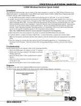
Figure 1: Connecting the AnyNET‑DMP Module Using the Uplink Power Supply
Switch No. Setting
S1 & S2 OFF
S3 & S4 Test Schedule
S3 S4 = OFF OFF None
S3 S4 = OFF ON Weekly
S3 S4 = ON OFF Daily
S3 S4 = ON ON Daily (Default)
S5, S6, S7, S8 OFF

Digital Monitoring Products 382 AnyNET-DMP Cable Installation Guide
2
Connecting Using the Uplink Power Supply
Refer to Figure 1 and the steps below to connect the AnyNET-DMP Module to the panel.
1. Complete the steps under Connecting the Module.
2. Plug the 382 Cable 9-pin connector onto the panel J21 RS-232 connector.
3. Plug the AnyNET-DMP power supply connector wire into the 12 VDC connector on the bottom of the
AnyNET-DMP Module. Plug the power supply unit into any 120 VAC 60 Hz outlet not controlled by a switch.
Connecting Using a DMP Power Supply
Refer to Figure 2 and the steps below to connect the AnyNET-DMP Module to the panel and DMP power supply.
1. Complete the steps under Connecting the Module.
2. When connecting the AnyNET-DMP module to a DMP power supply, cut the wire loop next to the 382 Cable
DB-25 connector. Insulate and secure the wire ends from accidentally shorting within the assembly.
3. Use a small at head screwdriver to loosen the screws and remove the AnyNET-DMP power supply wires from
the plug-on connector.
4. Insert 22 AWG Red (+) and Black (-) wires into the two slots and tighten the screws to hold the wires in place.
5. Run the Red (+) wire into the enclosure and connect to the 505 Series Power Supply J6 (+) connector.
6. Run the Black (-) wire into the enclosure and connect to the 505 Series Power Supply J6 (-) connector.
7. Plug the power connector into the 12 VDC connector on the bottom of the AnyNET-DMP Module.
8. Plug the 382 Cable 9-pin connector onto the panel J21 RS-232 connector.
Note: Verify that all devices are connected and wiring is complete prior to panel power‑up.
Uplink AnyNet Module
Base Connectors
Network
12 VDC
+ –
Out-
put
2
Signal Interface
505
-1
2
Power Su
pp
l
y
A
C
Tr
oub
l
e
B
a
tt
Tr
oub
l
e
J
3
DC
G
ree
n
LED
AC
J2
Power Supply Connetion
Black —
Red +
AC
1
2
345678 10 11 12 13
14
15
1
6
17 18 199202122232425262728
+B BELLGND SMK GNDREDYEL GRNBLK Z1 Z2 Z3 Z4 Z5 Z6 Z7 Z8 Z9+Z9– Z10+Z10–AC –B GNDGND GNDGND
K6 K7
Output 1 Output 2
J3
Phone
Line
J10
J22
LX-Bus
Battery
Start
J23
J21
RS-232
Power
LED
J8
PROG
J4
Tamper
J16
Reset
Out1 Out2
Outputs 3-6
J11
3
4
5
6
J2
J1
Ethernet
J6
Interface
Card
Expansion
Connector
XR500 Series
Command Processor™
Panel
R
L
X
RED
OVC
Resistors
1.0k Ohm - Zones 1-8
3.3k Ohm - Zones 9-10
1.0k Ohm - Bell Circuit Supervision
Plug into
XR500N J21,
RS-232, 9-pin
connector
Plu
g
into Uplin
k
Si
g
nal Interface
2
5
-Pin c
o
nnect
o
r
1K E
OL
1K E
OL
Br
o
w
n
White
Cut Loop
when
co
nn
ected
to DMP
Power
Supply
AnyNET Network Fail Supervision
AnyNET Interface
Cable Supervision
3
8
2-6
or
3
8
2-50 Cable
Figure 2: Connecting the AnyNET‑DMP Module Using a DMP Power Supply

382 AnyNET-DMP Cable Installation Guide
Digital Monitoring Products
Connecting Using a 462N Module
Refer to Figure 3 and the steps below to connect the AnyNET-DMP Module to the panel and the 462N Module.
1. Verify the jumper on the panel J23 6-Pin header is on the “L” or “X” position.
2. Complete steps 2-5 under Connecting the Module.
3. When connecting the AnyNET-DMP module to a DMP power supply, cut the wire loop next to the 382 Cable
DB-25 connector. Insulate and secure the wire ends from accidentally shorting within the assembly.
4. Plug the 462N Module onto the panel J6 Interface Card Expansion Connector.
5. Connect power as described in Connecting Using a DMP Power Supply.
6. Plug the 394 Cable RJ end into the RJ connector on the 462N Module.
7. Plug the 382 Cable 9-pin connector onto the 394 Cable 9-pin connector.
8. As needed, connect expansion modules to the Zone Expansion harness from the 462N Module.
Note: Verify that all devices are connected and wiring is complete prior to panel power‑up.
9. After panel power-up, briey reset the panel using the J16 jumper to activate 462N operation.
AC
12345678 10 11 12 13 14 15 16 17 18 199202122232425262728
+B BELLGND SMK GNDREDYEL GRNBLK Z1 Z2 Z3 Z4 Z5 Z6 Z7 Z8 Z9+ Z9–Z10+Z10–AC –B GND GND GNDGND
K6 K7
Output 1 Output 2
J3
Phone
Line
J10
J22
LX-Bus
Battery
Start
J23
J21
RS-232
Power
LED
J8
PROG
J4
Tamper
J16
Reset
Out1 Out2
Outputs 3-6
J11
3
4
5
6
J2
J1
Ethernet
XR500 Series
Command Processor™
Panel
R
L
X
RED
OVC
Resistors
1.0k Ohm - Zones 1-8
3.3k Ohm - Zones 9-10
1.0k Ohm - Bell Circuit Supervision
Plu
g
into
Uplink Si
g
nal
Interf
a
ce 2
5
-Pin
c
o
nnect
or
1K E
OL
1K E
OL
Br
o
w
n
White
e
462N
Network
Interface
Card
Zone Expansion Harness Bl
a
c
k
G
ree
n
Yell
ow
Re
d
3
94 C
a
bl
e
J6
Interface
Card
Expansion
Connector
Uplink AnyNet Module
Base Connectors
Network
12 VDC
+ –
Out-
put
2
Signal Interface
505
-1
2
Power Su
pp
l
y
AC
Batt
J3
A
J2
Black —
Red +
Cut Loop
when
co
nn
ected
to DMP
Power
Supply
AnyNET Network
Fail Supervision
AnyNET
Interf
a
c
e
C
ab
le
Supervision
382-6 or
3
8
2-50 Cable
NOTE: Set J23
to "X" when using
DMP Wireless.
Figure 3: Connecting the AnyNET‑DMP Module Using a DMP Power Supply and 462N Module

LT-0936 © 2008 Digital Monitoring Products, Inc.
800-641-4282
www.dmp.com
Made in the USA
INTRUSION • FIRE • ACCESS • NETWORKS
2500 North Partnership Boulevard
Springfield, Missouri 65803-8877
8322
Programming
Refer to the XR500 Series Programming Guide (LT-0679) and XR500 Installation Guide (LT-0681) as needed. Use
the following programming steps in Communications and Zone Information to congure the XR500 Series panel for
AnyNET-DMP backup communication.
Panel Software Versions below 200
1. Program the panel for Communications type NET and enter a remote IP Address.
2. Set NET BACKUP to YES but do not enter a modem string.
3. Set SUPERVISE BACKUP to NO.
4. Set 2ND LINE to 232 and:
• Set the J23 6-pin jumper to “R” to enable DB-9 operation (J21).
• Set the J23 6-pin jumper to “L” when a 462N card is installed.
5. Set TEST FREQ (Test Frequency) to REG (daily), 7 days, or 30 days to identify when a recall test message is
sent from the panel through the AnyNET-DMP module.
6. Program a NET FAIL TEST time to increase the frequency a recall test message is sent from the panel through
the AnyNET-DMP module during a period of network failure on the Remote IP Address (primary).
7. Program Zone 1 to indicate trouble in an open condition to monitor the cable connection between the
AnyNET-DMP Module and the panel.
8. Program Zone 2 to indicate a trouble in short condition to monitor the AnyNET-DMP Module network
communication. Additionally, in System Options, a supervisory zone retard delay of up to 250 seconds can be
programmed for Zone 2.
Panel Software Versions above 200
Set the panel J23 jumper to:
• “R” to enable DB-9 operation (J21).
• “L” when a 462N card is installed.
1. Program a panel Communication Path for 232 communication.
2. Program the path type as Primary or Backup.
3. Set TEST FREQ (Test Frequency) to 1 (daily), 7 (weekly), or 30 days to identify when a recall test message is
sent from the panel through the AnyNET-DMP module.
4. Program a NET FAIL TEST time to increase the frequency a recall test message is sent from the panel through
the AnyNET-DMP module during a period of network failure on the Primary path.
5. Program the 232 Comm Port the AnyNET module is using for communication. When using DB-9 operation,
select ‘O’ for the on-board connector. When installed with the 462N, program this option for the slot
(A, B, C, D or E) where the 462N is installed.
6. Program the 232 Setup String as the target IP Address for communication.
7. Program Zone 1 to indicate trouble in an open condition to monitor the cable connection between the
AnyNET-DMP Module and the panel.
8. Program Zone 2 to indicate a trouble in short condition to monitor the AnyNET-DMP Module network
communication. Additionally, in System Options, a supervisory zone retard delay of up to 250 seconds can be
programmed for Zone 2.
Specications
382-6 6’ DB-25 to DB-9 Cable
382-50 50’ DB-25 to DB-9 Cable
Compatibility
XR500, XR500N, and XR500E Command
Processor™ Panels
Listings and Approvals for AnyNET-DMP
UL 365 Police Connected Burglar
UL 636 Holdup Alarm Units and Systems Accessory
UL 985 Household Fire Warning
UL 1023 Household Burglar
UL 1076 Proprietary Burglar
UL 1610 Central Station Burglar
/