Page is loading ...

FA426 Wireless Receiver
Description
The FA426 Wireless Receiver allows you to add 16 FA series transmitters to an XR500 Series, XR100 Series, XRSuper6,
XR20, XR40, XR200, or XR200-485 panel keypad data bus. The FA426 mounts in the panel enclosure and connects to
the keypad data bus terminals using a Model 300 4-wire harness supplied with the module.
Important: You must use an FA116 Executive Programmer to program the wireless points.
On XR500 Series panels the FA426 Receiver only operates on the rst eight keypad addresses.
Model FA42
6
1
5
B
R
TXD
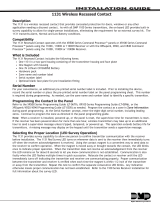
Mounting Holes (3)
Address Jumper
4-Pin Harness Connector
Programmer Connector
Transmit Data LED
Figure 1: FA426 Hardware Descriptions
Installing the FA426 Receiver
1. Touch the side of the enclosure with your hand to discharge any static electricity in your body before picking up
the FA426 module.
2. Mount the plastic standoffs to the enclosure with the three included Phillips head screws.
3. Insert the screws from the outside of the enclosure through the holes and into the plastic standoffs which
mount on the inside of the enclosure and tighten.
4. After securing the standoffs onto the enclosure, guide the two antennae through the openings in the top of the
enclosure.
5. Gently snap the FA426 onto the standoffs.
Connecting the FA426 Receiver
The FA426 receiver is attached to the panel using the supplied 4-wire harness that connects to the 4-pin harness
connector shown in Figure 1. The leads from the harness connect to the panel keypad data bus on terminals 7, 8, 9,
and 10. Table 1 describes the harness wiring connections.
Harness Wire Color Keypad Bus Terminal
Red 7
Yellow 8
Green 9
Black 10
Table 1: Connection to Keypad Data Bus
INSTALLATION GUIDE

Digital Monitoring Products FA426 Wireless Receiver Installation Guide
2
FA426 Wireless Receiver Installation Guide Digital Monitoring Products
3
Addressing the FA426 Receiver
Refer to Table 2 below as needed to set keypad addresses.
When the FA426 receiver is connected to an XRSuper6 or XR20, set the address jumper to address 1 (left two pins).
When connecting the FA426 to an XR500 Series, XR100 Series, XR40, XR200, or XR200-485 the receiver address
jumper may be set to either address 1 (left two pins) or address 5 (right two pins).
The FA426 responds on the corresponding keypad address when a transmitter point is programmed. For example, if
wireless point 2 is programmed on an XR20 at address 1 and goes into alarm, the FA426 signals an alarm on zone 12.
Wireless Points
XRSuper6 XR20 XR500 Series, XR100 Series,
XR40, XR200, and XR200-485
Zone Numbers:
Address 1
Zone Numbers:
Address 1
Zone Numbers:
Address 1
Zone Numbers:
Address 5
1 7 11 11 51
2 8 12 12 52
3 9 13 13 53
4 10 14 14 54
5 21 21 21 61
6 22 22 22 62
7 23 23 23 63
8 24 24 24 64
9 31 31 31 71
10 32 32 32 72
11 33 33 33 73
12 34 34 34 74
13 41 41 41 81
14 42 42 42 82
15 43 43 43 83
16 44 44 44 84
Note: The FA113 Arming Pendant only arms in Step style if the panel is in All/Perimeter or Home/Sleep/Away mode.
For XR500 Series, XR100 Series, XR200-485 panels using Area mode the arming button arms all assigned areas.
Table 2: Assigning Zones to Wireless Points
Wireless Arming
The FA113 Arming Pendant can be used on the XR500 Series, XR100 Series, XRSuper6, XR20, XR40, XR200, and
XR200-485 to allow for wireless arming and disarming. Program the transmitter for point 1 in the FA116 Executive
Programmer. You may use multiple arming pendants, but program all FA113 pendants to point 1. This will be zone
11 or zone 51, depending on how you have addressed the receiver (see Table 2). Program the zone as an Arming
type zone with the Style set as STEP in Zone Information programming. To enable the FA113 panic feature, select
YES for the Ambush option in System Reports programming.
Note: If you are not using an FA113 Arming Pendant, point 1 cannot be used.
Zone State Messages
The panel displays specic messages from an FA Receiver. Zone State OPEN indicates a transmitter tamper situation
and Zone State SHORT indicates an alarm trip situation regardless of the transmitter programming of Normally Open
(N/O) or Normally Closed (N/C) contacts.
The panic signal from the FA113 Arming Pendant displays at the central station receiver as Zone 19, Keypad 1 or 5.
Device Setup
When connected to the XR500 Series, XR100 Series, XR200, or XR200-485, in the Device Setup section of
programming, select STANDARD for each address that has a programmed zone. The XRSuper6, XR20, and XR40
automatically poll all available addresses, so additional panel programming is not necessary.

Digital Monitoring Products FA426 Wireless Receiver Installation Guide
2
FA426 Wireless Receiver Installation Guide Digital Monitoring Products
3
Addressing Examples
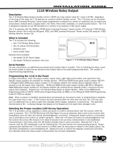
Figure 2 illustrates proper addressing congurations for XRSuper6 and XR20 panels when using the FA426 Receiver.
Figure 2: XRSuper6 and XR20 Addressing
Addressing XR500 Series, XR100 Series, XR40, XR200, and XR200-485 Panels
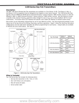
Figure 3 illustrates the proper addressing congurations for XR500 Series, XR100 Series, XR40, XR200, and XR200-485
panels when using the FA426 Receiver. Use either Address 1 or Address 5 with one FA426 Receiver. Refer to
Addressing the FA426 Receiver for more information.
Addressing Two FA426 Receivers
With the XR500 Series, XR100 Series, XR40, XR200, or XR200-485 you can install two FA426 wireless receivers on the
keypad bus. Set one receiver to address 1 and the other receiver to address 5. See Figure 3. Allow one address for
each supervised keypad or zone expander, or assign one address for all keypads in the unsupervised mode.
Important: When using two FA426 wireless receivers, each FA426 must be assigned a unique system ID number.
Figure 3: XR500 Series, XR100 Series, XR40, XR200, or XR200-485 Addressing with One or Two Receivers
Transmitter Programming Options
The following table provides programming options for various FA series wireless transmitters.
Program Option 110/113 201 202 203S/D 205S/D 206 207 209 200/210 200W-210W 250 570/575
Internal Contact N/A No No No No No No No No No or Yes No N/A
End of Line N/A No No No No No No No No or Yes No or Yes No or Yes N/A
External Switch Type N/A N/O N/C N/O N/O N/C N/O N/O N/C or N/O N/C or N/O* N/C or N/O N/A
Check-in Time None 10-60 10-60 10-60 10-60 10-60 10-60 10-60 10-60 10-60 10-60 10-60
* 210W must be programmed Normally Open (N/O) if internal contact is used.
Table 3: FA Series Programming Options

LT-0313 (11/06) © 2006 Digital Monitoring Products, Inc.
INTRUSION • FIRE • ACCESS • NETWORKS
2500 North Partnership Boulevard
800-641-4282
www.dmp.com
Made in the USA Springeld, Missouri 65803-8877
Programming Points with the FA116 Executive Programmer
Follow the steps below to program the wireless points using an FA116 Executive Programmer (version 1.50 or higher).
Make sure the FA426 Receiver is installed and connected to the panel keypad data bus before programming.
Figure 4: FA116 Executive Programmer
Specications
Current Draw
Power 12 VDC from panel
Maximum 47 mA
Dimensions
Receiver 3.875" H x 2.625 W
Antenna 3" long
Listings and Approvals
FCC Part 15
Compatibility
The FA426 Receiver is compatible with the following
panels: XR500 Series, XR100 Series, XRSuper6, XR20,
XR40, XR200 or XR200-485.
Accessories
FA113 Arming Pendant
FA116 Executive Programmer
/