Page is loading ...

sec.3c
−−−−
1
BIBUS 2
nd
Ed. VOP - Technical Manual
SECTION 3C
(REV.G)
Mod. 725 PANEL
WITH DOOR UNIT
AND DIGITISER
LOUDSPEAKING UNIT WITH BUILT-IN
DIGITALIZER DEVICE Ref. 1072/19A 2
PERFORMANCE ..............................................................................2
STRUCTURE ....................................................................................2
DESCRIPTION OF TERMINAL BOARDS .........................................2
TECHNICAL SPECIFICATIONS ........................................................2
DEFAULT PROGRAMMING .............................................................3
CONNECTIONS ................................................................................3
FUNCTION .......................................................................................3
Calls ..............................................................................................3
Staircase lights function ...............................................................3
Busy function ................................................................................3
ADJUSTMENTS ...............................................................................3
Volume regulation .........................................................................3
Troubleshooting ............................................................................3
PROGRAMMING See section 1A
16-PUSHBUTTON EXPANSION MODULE Ref. 1038/17 4
DESCRIPTION OF TERMINALS .......................................................4
TECHNICAL SPECIFICATIONS ........................................................4
ADAPTER DEVICE FOR TV CAMERA Ref. 1742/13A 4
CAMERA UNIT ASSEMBLY INSTRUCTIONS Mod. 725 ..................4
INSTRUCTIONS FOR ASSEMBLY ON TV CAMERA MODULE
WITH ADJUSTABLE CCD CAMERA Ref. 1810/70 ..........................4
Download from www.urmet.com Technical Manuals area.
SECTION CONTENTS
PANELS WITH ANODIZED ALUMINIUM FRONT PLATE
Mod. 725 5
CAMERA UNIT .................................................................................5
Front plate and embedding box group Ref. 725/602 ................... 5
Ccd tv camera Ref. 725/600 ........................................................5
PRODUCT LIST ................................................................................ 6
INSTALLATION .................................................................................6
DOOR PHONE SYSTEMS - Dimensions ..........................................7
DOOR PHONE SYSTEMS
Examples of modular constructions with various capacities ........... 8
VIDEO DOOR PHONE SYSTEMS - Dimensions ............................10
VIDEO DOOR PHONE SYSTEMS
Examples of modular constructions with various capacities ......... 11

2
−−−−
sec.3c
Mod. 725 PANEL WITH DOOR UNIT AND DIGITISER
BIBUS 2
nd
Ed. VOP - Technical Manual
LOUDSPEAKING UNIT WITH BUILT-IN
DIGITALIZER DEVICE Ref. 1072/19A
PERFORMANCE
Can be installed with Urmet 725 two-row push-button panels.
18 user terminals which can be directly connected to buttons.
Connector for 16 user expansion module Ref. 1038/17.
Maximum four expansion modules (connected in series) for
maximum 82 user buttons in each door unit.
Possibility of assigning alphanumeric call button code with letter
prex or sufx A-J.
The digitiser is programmed by means of an external programming
device Ref. 1072/60 which in turn must be connected to a push-
button panel Ref. 1032/65.
Simplied programming with LED button and two dip-switches in
simple systems.
Possibility of programming one or more buttons for controlling a
special decoder (“staircase lights” function).
Electrical relay load control actuator with NC-C-NO outputs and
programmable activation time, from 1 to 30s.
Programmable door phone hang-up waiting time (10, 20, 30, 40s).
Programmable minimum guaranteed conversation time (10, 20, 30,
40s).
Maximum conversation time: 250s.
Open door contact input.
Hall button timed input.
Acoustic call sent signal.
Busy function signalled by busy tone when a button is pressed to
busy time-out.
Two trimmers for adjusting speaker and microphone volume.
Opto-isolated control signal management for video door phone
systems.
Possibility of programming a pre-set button for direct switchboard
calls (day state only).
•
•
•
•
•
•
•
•
•
•
•
•
•
•
•
•
•
•
•
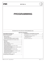
STRUCTURE
The door unit with digitiser consists of the following parts:
1 Speaker.
2 Main terminal board.
3 Simplied programming dip-switch.
4 Programming adapter connector Ref. 1072/60.
5 Simplied programming button and LED.
6 Microphone.
7 Microphone volume adjustment.
8 Speaker volume adjustment.
9 Button terminal board.
10 Expansion connector Ref. 1038/17.
DESCRIPTION OF TERMINAL BOARDS
System terminal boards
NO Electrical lock relay normally open contact
NC Electrical lock relay normally closed contact
C Relay exchange electrical lock common contact
~12 Relay power for electrical lock
~0 Relay power for electrical lock
SN Video power unit on signal for video door phone systems
R
Video switching enable signal for video door phone systems
R1 Video power earth
L1 Bus Line 1st connector
L2 Bus Line 2nd connector
GND Reference earth PA, SP.
SP Open door sensor contact input (closed with closed door)
PA Hall door opener button input (normally open)
Button terminal boards
P1÷P18 User button inputs
C Button reference earth
TECHNICAL SPECIFICATIONS
Stand-by consumption: 6.5mA max.
Active voice consumption: 40mA max.
Relay contact: 30V 2A
R, SN signal: Imax=80mA
Working temperature range: -10 ÷ +50°C
Humidity: 90% RH at 30°C
•
•
•
•
•
•
LOUDSPEAKING UNIT WITH BUILT-IN DIGITALIZER DEVICE Ref. 1072/19A
PERFORMANCE - STRUCTURE - DESCRIPTION OF TERMINAL BOARDS - TECHNICAL SPECIFICATIONS
C
1
8
1
6
1
7
1
5
1
4
1
3
1
1
1
2
10
9
8
7
6
5
4
2
3
1
EXT
INT
S
ch. 1072/19A
Sett/Fab
E
X
T
IN
T
Sch. 1072/19A
S
ett/F
ab
1
6
7
9
2
5
3
4
8
10
LOUDSPEAKER UNIT WITH BUILT-IN DIGITALIZER DEVICE
Ref. 1072/19A

sec.3c
−−−−
3
Mod. 725 PANEL WITH DOOR UNIT AND DIGITISER
BIBUS 2
nd
Ed. VOP - Technical Manual
DEFAULT PROGRAMMING
Refer to section 1A “Programming” in this manual for how to
program the device.
The device default settings are:
System type: 2nd edition
Station type: main
Code format: numeric (0001–9999)
Station number: 1
Off-hook waiting time: 40s
Busy time: 20s
Door opener time: 3s
Code button association
LLLL P1
1002 P2
. .
. .
. .
1082 P82
To restore default settings, insert the programming device and hold
bs (back space) button pressed for longer than three seconds until
you hear a beep.
Alternatively, without the programming device, hold the programming
button (5) pressed for longer than three seconds until you hear a
beep.
CONNECTIONS
IMPORTANT: Observe the instructions contained in section 1 for
wiring and maximum distances.
Up to 18 user buttons can be connected directly to the door unit.
When a higher number of user is required, a Ref. 1038/17 expansion
module can be connected. This allows the addition of 16 user buttons
to the 18 basic buttons. Up to four expansion units can be connected
to each door unit, for a total of 82 user buttons.
Position two call units side by side if a station with more than 82 users
is required. The door unit is programmed by default with a jumper
between the earth and the “SP” signal to simulate the door closed
contact. Remove the jumper and connect the sensor between GND
and SP when the open door contact is required.
Internal calling station circuits are power by bus voltage.
FUNCTION
CALLS
Up to 82 users can be called by pressing the corresponding buttons on
the panels associated to the door unit with digitiser Ref. 1072/19A.
Additionally, a concierge switchboard Ref. 1072/42 can be called,
simply by pressing a call button associated to code 0000 during
programming (day mode only). A courtesy ring, similar to that
generated on a called door phone, will be heard.
STAIRCASE LIGHTS FUNCTION
Press the button programmed for this function. A command will be
sent to the special decoder and a conrmation beep will be heard.
The staircase light function is assigned to button P1 by default.
If the staircase lights button is pressed during the programming
procedure, it will be reprogrammed with the user code
corresponding to the position.
§
•
•
•
•
•
•
•
§
§
BUSY FUNCTION
This function is only required in systems with more than one calling
device. This function is used to ensure that a conversation lasts
sufciently long following a call. An intermittent beep will be heard on
the speaker for the time before the busy time-out and the panel will
be disabled.
Two cases can occur:
BUSY TIME BEFORE THE CALL USER GOES ON-HOOK
This is the maximum time for the user to lift the handset or open the
door without loosing the call after the ring.
BUSY TIME AFTER USER GOES ON-HOOK
This is the minimum guaranteed conversation time from when the
handset is lifted.
ADjUSTMENTS
VOLUME REGULATION
Volume levels are calibrated by default so not to require adjustments
in most cases.
Use a screwdriver to adjust the trimmers if required.
TROUBLESHOOTING
Establishing the cause of problems related to a door unit with digitiser
Ref. 1072/19A is simple (e.g. no courtesy tone after a call button is
pressed):
Short-circuit on push-button panel side (L1, L2).
Neither bus couplers are programmed as masters.
•
•
LOUDSPEAKING UNIT WITH BUILT-IN DIGITALIZER DEVICE Ref. 1072/19A
DEFAULT PROGRAMMING - CONNECTIONS - FUNCTION - ADJUSTMENTS
LOUDSPEAKER UNIT WITH BUILT-IN DIGITALIZER DEVICE
Ref. 1072/19A

4
−−−−
sec.3c
Mod. 725 PANEL WITH DOOR UNIT AND DIGITISER
BIBUS 2
nd
Ed. VOP - Technical Manual
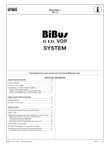
16-PUSHBUTTON EXPANSION MODULE
Ref. 1038/17
The extension module can be used to add 16 user buttons to the
door unit.
Arrange the device in the push-button panels, as shown in the
following gure.
Connect the user buttons and connect the device to the door unit and
to other extensions by means of the specic wire. Respect the
connections and the holes in the ush mounting boxes.
Insert the device in a free bulb holder.
DESCRIPTION OF TERMINALS
C Electrical reference earth for buttons 1-8
P1...P8 User buttons
C Electrical reference earth for buttons 9-16
P9..P16 User buttons
TECHNICAL SPECIFICATIONS
Consumption: 1mA Max
Current in user button: ~1mA
Working temperature range: +0°C - +50°C
Humidity: 90% RH at 30°C
•
•
•
•
16-PUSHBUTTON EXPANSION MODULE Ref. 1038/17
ADAPTER DEVICE FOR TV CAMERA Ref. 1742/13A
Other
expansion
modules
To the
digitizer
Sch. 1038/17
OUTPUT INPUT
Sch. 1038/17
OUTPUT INPUT
S.R.L.S.R.L.
S.R.L.S.R.L.
ADAPTER DEVICE FOR TV CAMERA
Ref. 1742/13A
The device is used in Bibus 2nd edition VOP video door phone
systems.
The adapter must be used in combination with cameras Ref.
725/600.
The adapter transforms the composite video signal from the camera
into two differential video signals (A and B).
CAMERA UNIT ASSEMBLY INSTRUCTIONS
Mod. 725
16-PUSHBUTTON EXPANSION MODULE
ADAPTER DEVICE FOR TV CAMERA
Ref. 1038/17
Ref. 1742/13A

sec.3c
−−−−
5
Mod. 725 PANEL WITH DOOR UNIT AND DIGITISER
BIBUS 2
nd
Ed. VOP - Technical Manual
Terminal board for connecting the camera unit are arranged on the
front panel:
+TC Camera power positive input
R1 Camera power negative input
V5/B Differential video signal output (positive)
V3/A Differential video signal output (negative)
Relay box or Ref. 788/52 must be used for correctly connecting
the camera unit in Bibus 2nd edition VOP systems.
CCD TV CAMERA Ref. 725/600
Easy to insert and to remove from the embedding box, it is supplied
complete of:
TV camera with optics and incorporated shutter; the focus
arrangement is xed. Other lenses cannot be used.
Coupling for connection to the front plate.
§
•
•
PANELS WITH ANODIZED ALUMINIUM FRONT
PLATE Mod. 725
725 panel with aluminium front plate is modular. Various door phone
and video door phone congurations can be made by arranging panels
and camera units where relevant to obtain the required capacity.
Two-row panels only can be installed to create from 4 to 82 user
systems.
All 725 products, characteristics and installation procedures are
shown in Technical product manual - door phone and video door
phone systems section “Panels with anodized aluminium front plate
Mod. 725”.
CAMERA UNIT
The following camera unit must be used in combination with 725
panels with door unit and digitiser Ref. 1072/19A in VOP video door
phone systems:
Front with ush-mounting box and lights.
CCD camera and lens.
FRONT PLATE AND EMBEDDING BOX GROUP
Ref. 725/602
The group Ref. 725/602, with front plate width 205 mm, can be coupled
to push button panels Mod. 725 with 4 to 28 buttons on 2 rows.
For installation, join the embedding box of the TV camera unit with
the push button panel embedding box by means of the white wire-
spacers (supplied with the TV camera unit). In case of coupling of 2 or
more push button panels, couple the embedding boxes by means of
the proper black wire-spacers supplied with the push button panels
on 2 rows not arranged for loudspeaking unit
§
•
•
PANELS WITH ANODIZED ALUMINIUM FRONT PLATE Mod. 725
CAMERA UNIT
Ref. 725/602
WHITE
COLOUR
BLACK
COLOUR
PANELS WITH ANODIZED ALUMINIUM FRONT PLATE
Mod. 725

6
−−−−
sec.3c
Mod. 725 PANEL WITH DOOR UNIT AND DIGITISER
BIBUS 2
nd
Ed. VOP - Technical Manual
INSTALLATION
Fit the adhesive rubbers on the door unit and digitiser.
Assemble the panel and camera unit where relevant as shown in the
following gure.
PANELS WITH ANODIZED ALUMINIUM FRONT PLATE Mod. 725
PRODUCT LIST - INSTALLATION
Ref. 725/602
Ref. 1742/13A
Ref. 725/600
Ref. 725/204÷228
Ref. 1072/19A
PANELS WITH ANODIZED ALUMINIUM FRONT PLATE
Mod. 725
PRODUCT LIST
Pushbutton with two rows of buttons and door unit set-up
With 4 buttons Ref. 725/204
With 6 buttons Ref. 725/206
With 8 buttons Ref. 725/208
With 10 buttons Ref. 725/210
With 12 buttons Ref. 725/212
With 14 buttons Ref. 725/214
With 16 buttons Ref. 725/216
With 18 buttons Ref. 725/218
With 20 buttons Ref. 725/220
With 22 buttons Ref. 725/222
With 24 buttons Ref. 725/224
With 26 buttons Ref. 725/226
With 28 buttons Ref. 725/228
Pushbutton with two rows of buttons without door unit set-up
With 20 buttons Ref. 725/020
With 22 buttons Ref. 725/022
With 24 buttons Ref. 725/024
With 26 buttons Ref. 725/026
With 28 buttons Ref. 725/028
With 34 buttons Ref. 725/034
Case and hood for 2-row door phone panels
With 4-10 buttons with door unit set-up Ref. 725/721
With 12-24 buttons with door unit set-up or
with 20-32 buttons without door unit set-up Ref. 725/722
Anti-rain hood cover
Anti-rain hood cover for 2 rows front plate Ref. 725/702
•
•
•
•
•
•
•
•
•
•
•
•
•
•
•
•
•
•
•
•
•
•

sec.3c
−−−−
7
Mod. 725 PANEL WITH DOOR UNIT AND DIGITISER
BIBUS 2
nd
Ed. VOP - Technical Manual
PANELS WITH ANODIZED ALUMINIUM FRONT PLATE Mod. 725
DOOR PHONE SYSTEMS
DIMENSIONS
1,5 m
43
mm
194 mm
H1
399 mm
H1
604 mm
H1
410 mm
H2
615 mm
H2
205 mm
H2
§ Position the lower edge of the push-button panel at a height of approximately 1.50 metres from the floor.
4 rows2 rows 6 rows
2 rows 4 rows 6 rows
4
6
8
10
12 32
14 36
16 40
18 44 70
20 48 76
22
24
26 60
28
Dimension
Height (mm)
Flush H1 Front H2
177 192
201 216
225 240
249 264
273 288
297 312
321 336
345 360
369 384
393 408
417 432
441 456
465 480
Dimension Flush 194 399 604
Width (mm) Front 205 410 615
Number of buttons on panel
PANELS WITH ANOD. ALUMIN. FRONT PLATE - DOOR PHONE SYSTEMS
Mod. 725

8
−−−−
sec.3c
Mod. 725 PANEL WITH DOOR UNIT AND DIGITISER
BIBUS 2
nd
Ed. VOP - Technical Manual
PANELS WITH ANODIZED ALUMINIUM FRONT PLATE Mod. 725
DOOR PHONE SYSTEMS
EXAMPLES OF MODULAR CONSTRUCTIONS WITH VARIOUS CAPACITIES
Door unit with digitiser
16-users expansion module
Buttons set up for door unit
Buttons not set up for door unit
Wall mounting box with hood
1072/19A 1072/19A 1072/19A 1072/19A
- - - -
725/204 725/206 725/208 725/210
- - - -
725/721 725/721 725/721 725/721
4 6 8 10
Door unit with digitiser
16-users expansion module
Buttons set up for door unit
Buttons not set up for door unit
Wall mounting box with hood
1072/19A 1072/19A 1072/19A 1072/19A
- - - -
725/212 725/214 725/216 725/218
- - - -
725/722 725/722 725/722 725/722
12 14 16
18
Door unit with digitiser
16-users expansion module
Buttons set up for door unit
Buttons not set up for door unit
Wall mounting box with hood
1072/19A 1072/19A 1072/19A 1072/19A
1 x 1038/17 1 x 1038/17 1 x 1038/17 1 x 1038/17
725/220 725/222 725/224 725/226
- - - -
725/722 725/722 725/722 -
20 22 24 26
Door unit with digitiser
16-users expansion module
Buttons set up for door unit
Buttons not set up for door unit
Wall mounting box with hood
1072/19A 1072/19A 1072/19A 1072/19A
1 x 1038/17 1 x 1038/17 2 x 1038/17 2 x 1038/17
725/228 725/212 725/214 725/216
- 725/020 725/022 725/024
- - - -
28 32 4036
PANELS WITH ANOD. ALUMIN. FRONT PLATE - DOOR PHONE SYSTEMS
Mod. 725

sec.3c
−−−−
9
Mod. 725 PANEL WITH DOOR UNIT AND DIGITISER
BIBUS 2
nd
Ed. VOP - Technical Manual
PANELS WITH ANODIZED ALUMINIUM FRONT PLATE Mod. 725
DOOR PHONE SYSTEMS
EXAMPLES OF MODULAR CONSTRUCTIONS WITH VARIOUS CAPACITIES
7670
60
Door unit with digitiser
16-users expansion module
Buttons set up for door unit
Buttons not set up for door unit
Wall mounting box with hood
1072/19A 1072/19A 1072/19A
2 x 1038/17 2 x 1038/17 3 x 1038/17
725/218 725/220 725/226
725/026 725/028 725/034
- - -
44 48
Door unit with digitiser
16-users expansion module
Buttons set up for door unit
Buttons not set up for door unit
Wall mounting box with hood
1072/19A 1072/19A
4 x 1038/17 4 x 1038/17
725/218 725/220
2 x 725/026 2 x 725/028
- -
PANELS WITH ANOD. ALUMIN. FRONT PLATE - DOOR PHONE SYSTEMS
Mod. 725

10
−−−−
sec.3c
Mod. 725 PANEL WITH DOOR UNIT AND DIGITISER
BIBUS 2
nd
Ed. VOP - Technical Manual
PANELS WITH ANODIZED ALUMINIUM FRONT PLATE Mod. 725
VIDEO DOOR PHONE SYSTEMS
DIMENSION
1,55 ÷ 1,60 m
53 mm
43
mm
194 mm
H1
399 mm
H1
604 mm
H1
410 mm
H2
205 mm
H2
615 mm
H2
4 rows2 rows 6 rows
2 rows 4 rows 6 rows
4
6 30
8 34 60
10 38 66
12
14
16 50 max. 82
18
20
22
24
26
28
Dimension
Height (mm)
Flush H1 Front H2
297 312
321 336
345 360
369 384
393 408
417 432
441 456
465 480
489 504
513 528
537 552
561 576
585 600
Dimension Flush 194 399 604
Width (mm) Front 205 410 615
Number of buttons on panel
§ Position the button so that the upper edge of the camera unit flush mounting box is at a height of approximately 1.50÷1.60 metres
from the ground.
PANELS WITH ANOD. ALUMIN. FRONT PLATE - VIDEO DOOR PHONE SYSTEMS
Mod. 725

sec.3c
−−−−
11
Mod. 725 PANEL WITH DOOR UNIT AND DIGITISER
BIBUS 2
nd
Ed. VOP - Technical Manual
PANELS WITH ANODIZED ALUMINIUM FRONT PLATE Mod. 725
VIDEO DOOR PHONE SYSTEMS
EXAMPLES OF MODULAR CONSTRUCTIONS WITH VARIOUS CAPACITIES
Door unit with digitiser
16-users expansion module
Camera
Adapter for TV camera
Front unit
Push-button panel
Hood
1072/19A 1072/19A 1072/19A 1072/19A
- - - -
725/600 725/600 725/600 725/600
1742/13A 1742/13A 1742/13A 1742/13A
725/602 725/602 725/602 725/602
725/204 725/206 725/208 725/210
725/702 725/702 725/702 725/702
4 6 8 10
Door unit with digitiser
16-users expansion module
Camera
Adapter for TV camera
Front unit
Push-button panel
Hood
1072/19A 1072/19A 1072/19A 1072/19A
- - - -
725/600 725/600 725/600 725/600
1742/13A 1742/13A 1742/13A 1742/13A
725/602 725/602 725/602 725/602
725/212 725/214 725/216 725/218
725/702 725/702 725/702 725/702
12 14 16 18
Door unit with digitiser
16-users expansion module
Camera
Adapter for TV camera
Front unit
Push-button panel
Hood
1072/19A 1072/19A 1072/19A 1072/19A
1 x 1038/17 1 x 1038/17 1 x 1038/17 1 x 1038/17
725/600 725/600 725/600 725/600
1742/13A 1742/13A 1742/13A 1742/13A
725/602 725/602 725/602 725/602
725/220 725/222 725/224 725/226
725/702 725/702 725/702 725/702
20 22 24 26
PANELS WITH ANOD. ALUMIN. FRONT PLATE - VIDEO DOOR PHONE SYSTEMS
Mod. 725

12
−−−−
sec.3c
Mod. 725 PANEL WITH DOOR UNIT AND DIGITISER
BIBUS 2
nd
Ed. VOP - Technical Manual
PANELS WITH ANODIZED ALUMINIUM FRONT PLATE Mod. 725
VIDEO DOOR PHONE SYSTEMS
EXAMPLES OF MODULAR CONSTRUCTIONS WITH VARIOUS CAPACITIES
Door unit with digitiser
16-users expansion module
Camera
Adapter for TV camera
Front unit
Push-button panel
Hood
1072/19A 1072/19A 1072/19A
1 x 1038/17 1 x 1038/17 1 x 1038/17
725/600 725/600 725/600
1742/13A 1742/13A 1742/13A
725/602 725/602 725/602
725/228 1 x 725/206 - 1 x 725/024 1 x 725/208 - 1 x 725/026
725/702 - -
28 30 34
Door unit with digitiser
16-users expansion module
Camera
Adapter for TV camera
Front unit
Push-button panel
Hood
1072/19A 1072/19A 1072/19A
2 x 1038/17 2 x 1038/17 3 x 1038/17
725/600 725/600 725/600
1742/13A 1742/13A 1742/13A
725/602 725/602 725/602
1 x 725/210 - 1 x 725/028 1 x 725/216 - 1 x 725/034 1 x 725/208 - 2 x 725/026
- - -
38 50 60
Door unit with digitiser
16-users expansion module
Camera
Adapter for TV camera
Front unit
Push-button panel
Hood
1072/19A 1072/19A
3 x 1038/17 4 x 1038/17
725/600 725/600
1742/13A 1742/13A
725/602 725/602
1 x 725/210 - 2 x 725/028 1 x 725/214 - 2 x 725/032
- -
66 max. 82
PANELS WITH ANOD. ALUMIN. FRONT PLATE - VIDEO DOOR PHONE SYSTEMS
Mod. 725
/