
sec.7
−−−−
1
BIBUS 2
nd
Ed. VOP - Technical Manual
SECTION 7
(REV. G)
SPARE PARTS
FOR RETROFIT
MAINTENANCE AND REPLACEMENTS ........................................2
REPLACING RELAY BOX Ref. 788/5 WITH Ref. 788/52 ...............3
REPLACEMENT OF THE VIDEO DISTRIBUTOR
Ref. 1074/54 WITH Ref. 1074/55 .....................................................4
Download from www.urmet.com Technical Manuals area.
SECTION CONTENTS

2
−−−−
sec.7
BIBUS 2
nd
Ed. VOP - Technical Manual
SPARE PARTS FOR RETROFIT
MAINTENANCE AND REPLACEMENTS
Some devices in the system may need to be replaced in time for
maintenance purposes. This paragraph indicates what needs to be
reprogrammed.
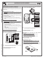
Door unit with digitiser Ref. 1072/19A:
Replacing door unit with digitiser Ref. 1072/18 with model
Ref. 1072/19A.
Make the wiring without changing the sequence of the buttons.
In video system with power unit Ref. 1772/6, video power terminal
GND must be connected to door unit terminal R1 and not to door
unit terminal GND.
Program the following parameters with programming adapter
Ref.1072/60 and keyboard Ref. 1032/65:
• System type: 1st Edition.
• Station number (ID): enter the value of the replaced station .
• Electrical lock energising time: enter the value of the replaced
station .
The door phones DO NOT need to be programmed.
Replacing door unit with digitiser Ref. 1072/19 or 1072/19A with
model Ref. 1072/19A.
Make the wiring without changing the sequence of the buttons.
Program the following parameters with programming adapter
Ref. 1072/60 and keyboard Ref. 1032/65:
• System type: 2nd Edition.
• Station number (ID): enter the value of the replaced station .
• Electrical lock energising time: enter the value of the replaced
station.
• Hang-up waiting time and busy time: enter the value of the
replaced station.
• Code type: enter the value of the replaced station.
• User codes: enter the value of the replaced station.
The door phones DO NOT need to be programmed.
DOOR UNIT WITH DIGITISER Ref. 1072/19A REPLACING MODEL
Ref. 1072/18 IN 1ST EDITION BIBUS SYSTEMS.
N.B.: The buttons associated to the expansion modules will not send
the call if the wire is not inserted correctly.
16-USER EXPANSION MODULE Ref. 1038/17:
No programming required.
16-USER EXPANSION MODULE Ref. 1038/17 REPLACING MODEL
Ref. 1072/16 1ST EDITION BIBUS SYSTEMS
N.B.: the buttons associated to the expansion modules will not send
the call if the wire is not inserted correctly.
50-USER BUS COUPLER Ref. 1072/24:
No programming required.
DOOR PHONE Ref. 1172/31-/32-/33 OR PABX ADAPTER
Ref. 1072/67:
1st Edition system replacement procedure.
Replace devices and reprogram from all calling stations
2nd Edition system replacement procedure.
Replace devices and reprogram from any calling station.
SPECIAL DECODER Ref. 1072/80:
Reprogram the decoder.
SWITCHBOARD Ref. 1072/41:
Replacing switchboard Ref. 1072/40 with model Ref. 1072/41.
Entirely reprogram the switchboard.
Replacing switchboard Ref. 1072/41 with the same model.
Replace the faulty device in the system. Remove component U9 from
the old device and t it in the new device to avoid reprogramming.
Make sure the direction is correct.
Sch. 1072/16
OUTPUT INPUT
Ref. 1072/19A
Four
conductor wire
EXT
INT
Sch. 1072/19A
Sett/Fab
PA
NO
SP
GND
L2
L1
R1
R
SN
~0
~12
C
NC
C
18
16
17
15
14
13
11
12
10
9
8
7
6
5
4
2
3
1
C
PROG.
ID
EXP
II ED.
MAINTENANCE AND REPLACEMENTS
P
A
N
O
S
P
GND
L
2
L
1
R
1
R
S
N
~
0
~
1
2
C
N
C
C
1
8
1
6
1
7
1
5
1
4
1
3
1
1
1
2
10
9
8
7
6
5
4
2
3
1
C
E
X
T
IN
T
Sch. 1072/18
S
e
tt/F
a
b
P
R
O
G
.
E
S
P
.
Sch. 1038/17
OUTPUT INPUT
Sch. 1072/16
OUTPUT INPUT
Ref. 1072/18
Four
conductor
wire
U9
MAINTENANCE AND REPLACEMENTS

sec.7
−−−−
3
BIBUS 2
nd
Ed. VOP - Technical Manual
SPARE PARTS FOR RETROFIT
CALLING MODULE WITH REPERTORY Ref. 1072/12:
Replacing switchboard Ref. 1072/15 with model Ref. 1072/12
Entirely reprogram the calling module.
N.B.: terminal R1 must be connected instead of terminal GND when
replacing the device in 1st Edition video systems.
Replacing switchboard Ref. 1072/12 with the same model.
Replace the faulty device in the system. Remove component U8 from
the old device and t it in the new device to avoid reprogramming.
Make sure the direction is correct.
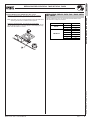
REPLACING RELAY BOX Ref. 788/5 WITH Ref. 788/52
U8
REPLACING RELAY BOX Ref. 788/5 Ref. 788/52
REPLACING RELAY BOX Ref. 788/5 WITH
Ref. 788/52
The Ref. 788/52 relay box can replace the obsolete 788/5 model.
The terminals correspond as follows:
Ref. 788/5
15
1
2
3
4
5
6
14
Ref. 788/52
15
S1
S2
S3
S4
S5
S6
14
CONTACTS
RELAY

4
−−−−
sec.7
BIBUS 2
nd
Ed. VOP - Technical Manual
SPARE PARTS FOR RETROFIT
REPLACEMENT OF THE VIDEO DISTRIBUTOR
Ref. 1074/54 WITH Ref. 1074/55
TO NEXT
DISTRIBUTORS
FLOOR VIDEO
DISTRIBUTOR
Sch.1074/54
VOP VIDEO AUDIO
VOP
VIDEO
AUDIO
Floor
call
button
Floor
call
button
Floor
call
button
Floor
call
button
RINGER
(optional)
TO NEXT
DISTRIBUTORS
FLOOR VIDEO
DISTRIBUTOR
Sch.1074/55
VOP
VIDEO
AUDIO
Floor
call
button
Floor
call
button
Floor
call
button
Floor
call
button
RINGER
(optional)
If the 1074/55 device is used instead of the 1074/54, connect the cables
of the video signal to the 1074/55 device as connected on the 1074/54.
The audio signal cables can be connected to the L1 L2 dedicated
connectors as indicated above or leaving the electrical connection set
up when using the 1074/54.
REPLACEMENT OF THE VIDEO DISTRIBUTOR
REPLACEMENT OF THE VIDEO DISTRIBUTOR
-
 1
1
-
 2
2
-
 3
3
-
 4
4


Ask a question and I''ll find the answer in the document
Finding information in a document is now easier with AI
Related papers
-
 urmet domus MT124-013 Technical Manual
-
 urmet domus MT124-013 Technical Manual
-
 urmet domus MT124-013 Technical Manual
-
 urmet domus MT124-013 Technical Manual
-
 urmet domus MT124-013 Technical Manual
-
 urmet domus MT124*013 Technical Manual
-
 urmet domus MT124-013 Technical Manual
-
 urmet domus MT124-013 Technical Manual
-
 urmet domus MT124-013 Technical Manual
-
 urmet domus MT124-013 Technical Manual


Other documents
-
Omega HCTB-1070 Series Owner's manual
-
Vertex VX-3R/E Technical Supplement
-
Trane AM7A0C42H31SA Series Field Reference Data
-
Yamaha RX-V465 User manual
-
Yamaha RX-V565 Owner's manual
-
Yamaha HTR-6250 User manual
-
Yamaha V665 - RX AV Receiver Owner's manual
-
Yamaha 6240 - HTR AV Receiver Owner's manual
-
-