Trane IntelliPak SXHF C50 User manual
- Category
- Heat pumps
- Type
- User manual

Packaged Rooftop
Air Conditioners
IntelliPak
™
Rooftops
20 - 130 Tons — 60 Hz
RT-PRC010-EN
March 2003
20 - 75 Tons
90 - 130 Tons

© 2003 American Standard Inc. All rights reserved
RT-PRC010-EN
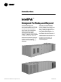
Introduction
IntelliPak
™
Designed For Today and Beyond
Innovative technology and an
impressive lineup of features make the
Trane IntelliPak Rooftop line the number
one choice for today and the future.
Trane’s rooftop Unit Control Module
(UCM), an innovative, modular
microprocessor control design,
coordinates the actions of the IntelliPak
rooftop in an efficient manner and allows
for stand-alone operation of the unit.
Access to the unit controls, via a Human
Interface Panel, provides a high degree
of control, superior monitoring
capability, and unmatched diagnostic
information.
Optionally, for centralized building
control on-site, or from a remote
location, IntelliPak can be configured for
direct communication with a Trane
Tracer™ building management system
or a 3
rd
party LonTalk building
management system, using a twisted
pair of wires. With one of these systems,
the IntelliPak status data and control
adjustment features can be conveniently
monitored from a central location.
IntelliPak has the technology
and
flexibility
to bring total comfort to
every building space.


RT-PRC010-EN4
Features and
Benefits
Standard Features
• 20 to 130 ton industrial/ commercial
rooftops
• Fully integrated, factory-installed/
commissioned microelectronic
controls
• Unit mounted Human Interface Panel
with a 2 line x 40 character English
display and a 16 function keypad that
includes Custom, Diagnostics, and
Service Test mode menu keys.
• Trane 3-D
™
Scroll compressors
(20 to 130 Tons)
• Compressor or circuit lead/lag
depending on unit
• Hinged access doors on control panel,
filter section, and gas heat section
• Horizontal discharge/return duct
connections (SX, SL, SS models)
• CV or VAV control
• Low ambient compressor lockout
control on units with economizers
• Frostat™ coil frost protection on
all units
• Daytime Warm-up (Occupied mode)
on VAV models and Morning Warm-up
operation on all units with heating
options
• Supply air static overpressurization
protection on units with inlet guide
vanes and VFD’s.
• Supply airflow proofing
• Exhaust airflow proofing on units with
exhaust option
• Supply air tempering control
• Supply air heating control on VAV
modulating hot water or steam heat
units
• Emergency stop input
• Liquid and Discharge Service Valves
• Mappable sensors and setpoint
sources
• Occupied/Unoccupied switching
• Timed override activation
• Forward-curved supply fans (20 - 75
ton models)
• Air foil supply fans (90 - 130 ton
models)
• Pitched roof over air handler section
• Stainless steel flue stack on gas heat
units
• 14-gauge, single-piece construction
base rails
• UL and CSA approval on standard
options
• Two-inch spring fan isolation
(90 to 130 tons)
• Meets 672 hours of salt spray testing in
accordance to ASTM B117 Standard
• Two inch standard efficiency
throwaway filters on 20 to 90 ton units
and two inch high efficiency
throwaway filters on 105 to 130 ton
units.
Optional Features
For a comprehensive listing of standard
options, special options, and
accessories, please see table O-1 starting
on page 96.
• Trane Communication Interface
Module: ICS interface control module
• LonTalk
®
Communication Interface
module
• Remote Human Interface Panel
(controls up to 4 units)
• Five ventilation override sequences
• Heating options: natural gas, electric,
hot water or steam
• Generic BAS interface
• Choose from three economizer control
options: comparative enthalpy,
reference enthalpy, dry bulb control
• Variable frequency drive control of
supply/exhaust fan motor
• Inlet guide vanes on FC supply fans
(VAV only)
• Outside air CFM compensation on VAV
units with IGV (or VFD) and economizer
• Hot gas bypass to the evaporator inlet
• Copper evaporator/condenser coils
• Suction service valves
• Replaceable core filter driers
• Phenolic coated evaporator/condenser
coils
• High capacity evaporator coils
(20 to 105 tons)
• Special paint colors
• Extended casing (SX models)
• Double wall access doors
• Double wall construction/perforated
double wall
• Stainless steel drain pan in evaporator
section
• Pitched evaporator drain pan
• Filter rack only (no filters)
• High efficiency throwaway filters
• 90-95 percent bag filters
• 90-95 percent cartridge filters
• Final filters
• Barometric relief
• 50 percent modulating exhaust with
forward-curved fans
• Trane’s air quality (Traq™) sensor
• Modulating Gas Heat
• 10 year limited warranty on Full
Modulation Gas Heat
• 100 percent modulating exhaust with
forward-curved fans
• 100 percent modulating exhaust with
FC fans and Statitrac™ direct space
sensing building pressurization control
• High duct temperature thermostats
• 0 F low ambient control
• 0-100 percent modulating fresh air
economizer
• Ultra low leak dampers for 0-100
percent modulating fresh air
economizers
• Dual electrical power connection
• Two-inch spring fan isolation
(20 to 75 tons)
• High efficiency motors
• U-frame motors
• Oversized motors
• Through the door non-fused
disconnect with external handle
• Electrical convenience outlet
• Power supply monitoring
• Correction capacitors
• Horizontal or Roof discharge w/gas
heat (20-75 tons “F” style units only)
Field Installed Accessories
• Roof curbs
• Programmable sensors with night set
back — CV and VAV
• Sensors without night set back — CV
and VAV
• Remote zone sensors — used for
remote sensing with remote panels.
• ICS zone sensors used with Tracer™
system for zone control
• Outdoor temperature sensor for units
without economizers
• Remote minimum position control for
economizer
• Field installed module kits available for
field upgrade of controls
Note: LonTalk and LonWorks are registered trademarks of Echelon Corporation.

5RT-PRC010-EN
Features Summary
IntelliPak™ rooftop features make
installation and servicing easy and
reliable operation a reality.
Installation Ease
• Factory-installed/commissioned
controls
—ease of start up
—single twisted wire pair
—communication for ICS interface
—full unit points access, no field wir-
ing of required points
• Unit mounted Human Interface Panel
standard
—user friendly keypad — edit
parameters
— through the access door interface
— start up adjustments
— unit mounted and remote in-
terface panel key pads are
identical
• Unit mounted lifting lugs facilitate
installation and can be used as unit
tiedown points.
Easy to Service
• The microprocessor unit controls
coordinates the operation of the
rooftop with quality, industry-accepted
components for service ease.
• Unit mounted Human Interface Panel
standard
— user friendly keypad — edit pa-
rameters
— through the access door interface
— start up adjustments
— unit mounted and remote interface
panel key pads are identical
• Modularity of unit control design
—individual replaceable functional
boards
• Advanced diagnostics
Reliability
• Advanced diagnostics
• Microprocessor controls
• Built-in safeties
• Modular control design
• UL approval as standard
• Forward-curved supply and exhaust
fans are Trane designed and factory
balanced.
• Fully insulated and gasketed panels
reduce ambient air infiltration.
• Fixed-speed evaporator fan and
exhaust drive for smooth fan operation
and belt durability.
• 200,000 average life fan bearings
enhance unit durability.
• Gas heater with free-floating stainless
steel heat exchanger relieves the
stresses of expansion and contraction.
Stainless steel provides corrosion
resistance through the entire material
thickness.
• Integral condenser subcooler improves
efficiency while helping avoid liquid
flashing.
• Factory-wired and commissioned
controls assure efficient and reliable
rooftop operation.
• Trane Scroll compressors are used on
20 to 130 ton units. They are designed
for tough industrial operation and
meet demanding operating conditions
both in efficiency and reliability.
• Roll-formed construction enhances
cabinet integrity and assures a
leakproof casing.
• Three-phase, direct-drive condenser
fan motors enhance dependability and
increase rooftop life.
• Trane industrial quality evaporator
and condensing coils help increase
rooftop life.
Application Flexibility
• Modularity in design
• Increased offering of standard options
• Generic BAS interface
• Five factory preset/re-definable in the
field ventilation override sequences
• Superior Tracer™ interface for ICS
applications
— factory-installed Trane
• Superior LonTalk interface for Tracer
and 3rd party applications
— factory-installed LonTalk
Communication Interface
• Unit mounted or Remote Human
Interface panels
— all parameter are editable from the
Human Interface Panel
• Comparative enthalpy, Reference
enthalpy, or Dry bulb control for
economizers
• Statitrac™ direct space building
pressure control
• Compensated outdoor air control —
IAQ
• Factory-installed filter rack includes
two-inch throwaway filters.
• CV controls stage both compressors
and heat based on space
requirements.
• Variable Frequency Drives (VFD)
Included With or Without Bypass
Control for Supply and Exhaust Fans.
• An array of heating options are
available, including Steam, Hot Water,
Electric and Natural Gas heat. The Gas
Heating option provides a choice of
two-stage gas heat, as well as full and
limited modulating gas heat.
Features and
Benefits

RT-PRC010-EN6
Features and
Benefits
Integrated
Rooftop
Systems:
Profitable,
Simple
Trane integrated rooftop systems make
design and installation of building
management systems cost effective and
easy. Trane offers two choices for
building management controls: Tracer
Building Automation System with a
Trane Control Interface (TCI) or Tracer
with LonTalk® Communication Interface
(LCI).
Integrated
Comfort with
Trane Tracer™
TCI
The Tracer TCI Integrated Comfort™
System (ICS) improves job profit and
increases job control by combining Trane
rooftop units with the Trane Tracer
building management system. This
integrated system provides total building
comfort and control. Some of the
primary motivations for building
owners/managers in deciding to
purchase a HVAC controls system is
energy savings, cost control, and the
convenience of facility automation.
Simplifying the Comfort System
Trane’s technology and innovation brings
more capabilities, more flexibility, and at
the same time, offers equipment and
systems that are easy to use, easy to
install, commission, and service. The
Tracer TCI Integrated Comfort system
saves time and money by simplifying
system design and system installation.
When used with Trane’s DDC/VAV boxes
(or VariTrane™), system balancing
almost goes away because each VAV box
is commission and tested before it
leaves the factory. All the status
information and editing data from the
rooftop units, VAV boxes, lighting,
exhaust and other auxiliary equipment is
available from Tracer TCI for control,
monitoring and service support of your
facility. Tracer, a family of building
automation products from Trane, is
designed with robust, application
specific software packages to minimize
custom programming requirements and
enable system setup and control
through simple editing of parameters in
the standard applications software.
Should you select an Integrated Comfort
system for your facility, the
accountability for equipment,
automation and controls is Trane’s,
Trane’s, and Trane’s!
The IntelliPak
rooftop, as a part of an
Integrated Comfort system, provides
powerful maintenance monitoring,
control and reporting capabilities. The
Tracer places the rooftop in the
appropriate operating mode for
operation for: system on/off, night
setback, demand limiting , setpoint
adjustment based on outside
parameters and much more. Up to 56
different unit diagnostic conditions can
be monitored through Tracer to let you
know about things like: sensor failures,
loss of supply airflow, and a compressor
trip out. Further, the addition of Building
Management Network software offers
remote scanning, automatic receipt of
alarms, and easy dial-up access to over
100 various Tracer sites across town or
across the country.
Typical points available through Tracer:
IntelliPak Rooftops monitoring points
available through Tracer
• all active Rooftop diagnostics
• history of last 20 unit diagnostics
• all system setpoints
• system sensor inputs
• supply fan mode and status
• inlet guide vane position/VFD speed
• unit heat/cool mode
• exhaust fan status
• exhaust damper position
• economizer position, minimum
position setpoint, economizing
setpoint
• on/off status of each compressor
• refrigerant evaporator and saturated
condenser temperatures
• hydronic heat valve position
• electric heat stage status
• ventilation override mode status
Tracer control points for IntelliPak
Rooftops
• cooling and heating setpoints
• zone setpoint offsets for use with
demand limiting
• VAV discharge air setpoints
• supply air pressure setpoint
• space pressure setpoint
• zone and outdoor temperature values
• cooling and heating enable/disable
• economizer enable/disable
• economizer setpoint
• economizer minimum position
• activation of ventilation override
modes
• diagnostics reset
• unit priority shutdown
IntelliPak Rooftops setup and
configuration information through Tracer
• supply fan mode
• configuration of supply air reset
• ventilation override mode
configuration
• default system setpoint values
• sensor calibration offsets
Interoperability
with LonTalk
The Trane Tracer LonTalk Control
Interface (LCI) for IntelliPak offers a
building automation control system with
outstanding interoperability benefits.
LonTalk, which is an industry standard, is
an open, secure and reliable network
communication protocol for controls,
created by Echelon Corporation and
adopted by the LonMark Interoperability
Association. It has been adopted by
several standards, such as: EIA-709.1, the

7RT-PRC010-EN
Features and
Benefits
The modular control design of the UCM
allows for greater application flexibility.
Customers can order exactly the options
required for the job, rather than one
large control package. Unit features are
distributed among multiple field
replaceable printed circuit boards. The
Trane UCM can be set up to operate
under one of three control applications:
1 stand-alone
2 interface with Trane’s Tracer™ building
management system
3 interface with a generic (non-Trane)
building management system. All
setup parameters are preset from the
factory, requiring less start-up time
during installation.
Electronic Industries Alliance (EIA)
Control Network Protocol Specification
and ANSI/ASHRAE 135, part of the
American Society of Heating,
Refrigeration, and Air-Conditioning
Engineer’s BACnet control standard for
buildings.
Interoperability allows application or
project engineers to specify the best
products of a given type, rather than one
individual supplier’s entire system. It
reduces product training and installation
costs by standardizing communications
across products. Interoperable systems
allow building managers to monitor and
control IntelliPak equipment with a Trane
Tracer Summit or a 3
rd
party building
automation system. It enables
integration with many different building
controls such as access/intrusion
monitoring, lighting, fire and smoke
devices, energy management, and a
wide variety of sensors (temperature,
pressure, light, humidity, occupancy,
CO2 and air velocity). For more
information on LonMark, visit
www.lonmark.org or Echelon,
www.echelon.com.
Optimum
Building
Comfort Control
The unit mounted Human Interface and
the Remote Human Interface Panels’
functions are identical, except for the
Service mode is not available on the
Remote Human Interface Panel. This
common interface feature requires less
time for building maintenance personnel
to learn to interact with the unit. All of the
rooftop’s control parameters are
adjustable and can be set up through the
Remote Human Interface Panel such as,
but not limited to: system on/off,
demand limiting type, night setback
setpoints, and many other setpoints. No
potentiometers are required for setpoint
adjustment, all adjustments are done
through the Remote Human Interface
keypad. Also up to 56 different rooftop
diagnostic points can be monitored
through the human interfaces such as:
sensor failures, loss of supply airflow,
and compressor trip. No special tools are
required for servicing of the unit. All
diagnostic displays are available in clear
English at the Remote Human Interface
and will be held in memory, so that the
operator/servicer can diagnose the root
cause of failures.
Statitrac™ Direct Space
Building Pressurization Control
Trane’s Statitrac™ control is a highly
accurate and efficient method of
maintaining building pressure control
with a large rooftop air conditioner.
The efficiency is achieved with a 100
percent modulating exhaust system with
two forward-curved fans with
modulating discharge dampers that
operate only when needed, compared to
some systems that operate continually.
And most of the operating hours of the
100 percent modulating exhaust system
are at part load, saving more energy.
Trane’s Statitrac, with the 100 percent
modulating exhaust system, provides
comfort and economy for buildings with
large rooftop air conditioning systems.
Statitrac control is simple! The space
pressure control turns the exhaust fans
on and off as required and modulates
exhaust dampers to maintain space
pressure within the space pressure dead
band. Using the unit mounted Human
Interface Panel you can
1) adjust space pressure setpoint
2) adjust space pressure dead band
3) measure and read building space
pressure. The modulating exhaust
system maintains the desired building
pressure, saving energy while keeping
the building at the right pressure. Proper
building pressurization eliminates
annoying door whistling, doors standing
open, and odors from other zones.
The Statitrac™ direct space building
control sequence will be maintained
when a variable frequency drive is used.
Fans With Inlet Guide Vanes
Trane’s forward curved fans (20 through
75 tons) and air foil fans (90 through 130
tons) with inlet guide vanes pre-rotate
the air in the direction of the fan wheel,
decreasing static pressure and
horsepower, essentially unloading the
fan wheel. The unloading characteristics
result in superior part load performance.
Variable Frequency Drives
(VFD)
Variable Frequency Drives are factory
installed and tested to provide supply/
exhaust fan motor speed modulation.
VFD’s, as compared to inlet guide vanes
or discharge dampers, are quieter, more
efficient, and are eligible for utility
rebates. The VFD’s are available with or
without a bypass option. Bypass control
will simply provide full nominal airflow
in the event of drive failure.

RT-PRC010-EN8
Features and
Benefits
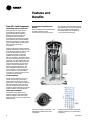
Trane 3-D
™
Scroll Compressor
Simple Design with 70% Fewer Parts
Fewer parts than an equal capacity
reciprocating compressor means
significant reliability and efficiency
benefits. The single orbiting scroll
eliminates the need for pistons,
connecting rods, wrist pins and valves.
Fewer parts lead to increased reliability.
Fewer moving parts, less rotating mass
and less internal friction means greater
efficiency than reciprocating
compressors.
The Trane 3-D Scroll provides important
reliability and efficiency benefits. The 3-D
Scroll allows the orbiting scrolls to touch
in all three dimensions, forming a
completely enclosed compression
chamber which leads to increased
efficiency. In addition, the orbiting scrolls
only touch with enough force to create a
seal; there is no wear between the scroll
plates. The fixed and orbiting scrolls are
made of high strength cast iron which
results in less thermal distortion, less
leakage, and higher efficiencies. The
most outstanding feature of the 3-D
Scroll compressor is that slugging will
not cause failure. In a reciprocating
compressor, however, the liquid or dirt
can cause serious damage.
Low Torque Variation
The 3-D Scroll compressor has a very
smooth compression cycle; torque
variations are only 30 percent of that
produced by a reciprocating compressor.
This means that the scroll compressor
imposes very little stress on the motor
resulting in greater reliability. Low torque
variation reduces noise and vibration.
Suction Gas Cooled Motor
Compressor motor efficiency and
reliability is further optimized with the
latest scroll design. Cool suction gas
keeps the motor cooler for longer life and
better efficiency.
One of two matched scroll plates — the
distinguishing feature of the scroll
compressor.
Chart illustrates low torque variation of
3-D Scroll compressor vs reciprocating
compressor.
Proven Design Through Testing and
Research
With over twenty years of development
and testing, Trane 3-D Scroll
compressors have undergone more
than 400,000 hours of laboratory testing
and field operation. This work combined
with over 25 patents makes Trane the
worldwide leader in air conditioning
scroll compressor technology.

9RT-PRC010-EN
Application
Considerations
EXHAUST AIR OPTIONS
When is it necessary to provide building
exhaust? Whenever an outdoor air
economizer is used, a building generally
requires an exhaust system. The purpose
of the exhaust system is to exhaust the
proper amount of air to prevent over or
underpressurization of the building. The
goal is to exhaust approximately 10
percent less air than the amount of
outside air going into the building. This
maintains a slightly positive building
pressure.
A building may have all or part of its
exhaust system in the rooftop unit. Often,
a building provides exhaust external to
the air conditioning equipment. This
external exhaust must be considered
when selecting the rooftop exhaust
system.
IntelliPak™ Rooftop units offer four types
of exhaust systems:
1
100 percent modulating exhaust with
Statitrac™ direct space sensing building
pressurization control (with or without
variable frequency drives).
2
100 percent modulating exhaust without
Statitrac.
3
50 percent power exhaust.
4
Barometric relief dampers.
Application Recommendations
1
100 percent modulating exhaust with
Statitrac™ control
For both CV and VAV rooftops, the 100
percent modulating exhaust discharge
dampers (or VFD) are modulated in
response to building pressure. A
differential pressure control system,
called Statitrac™, uses a differential
pressure transducer to compare indoor
building pressure to atmospheric
pressure. The FC exhaust fan is turned on
when required to lower building static
pressure to setpoint. The Statitrac control
system then modulates the discharge
dampers (or VFD) to control the building
pressure to within the adjustable,
specified dead band that is set at the
Human Interface Panel.
Advantages of the Statitrac™
100 percent modulating exhaust
system are:
a
The exhaust fan runs only when needed
to lower building static pressure.
b
Statitrac compensates for pressure
variations within the building from
remote exhaust fans and makeup
air units.
c
The exhaust fan discharges in a single
direction resulting in more efficient fan
operation compared to return fan
systems.
d
Because discharge dampers modulate
the airflow, the exhaust fan may be
running unloaded whenever the
economizer dampers are less than 100
percent open.
With an exhaust fan system, the supply
fan must be sized to pull the return air
back to the unit through the return
system during non-economizer
operation. However, a supply fan can
typically overcome return duct losses
more efficiently than a return air fan
system. Essentially, one large fan by itself
is normally more efficient than two fans
in series because of only one drive loss
not two as with return air systems.
The reason for either a return air fan or
an exhaust fan is to control building
pressure. The Trane 10 0 percent
modulating exhaust system with
Statitrac does a better job controlling
building pressure than return fans simply
because 100 percent modulating exhaust
discharge dampers (or VFD) are
controlled directly from building
pressure, rather than from an indirect
indicator of building pressure such as
outdoor air damper position.
The 100 percent modulating exhaust
system with Statitrac may be used on
any rooftop application that has an
outdoor air economizer. However, when
most exhaust is handled external to the
rooftop or when building pressure is not
critical, one of the other less expensive
methods of exhaust may be used.

RT-PRC010-EN10
Application
Considerations
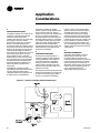
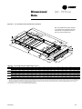
Figure AC-1 — Plan View of Modulating 100 Percent Exhaust System
2
100 Percent Exhaust System
Competitive rooftops use a return air fan
system for controlling the amount of
exhaust air during economizer
operation. The return fan is in series with
the supply fan and must operate
whenever the supply fan is operating.
During economizer operation, the
economizer outdoor air dampers control
the position of the return and exhaust air
dampers, to exhaust the proper amount
of air. The disadvantage of a return air
fan is that it runs continuously, versus an
exhaust fan system which runs only
when needed to lower or maintain
building static pressure. Also, the return
fan must discharge air in two directions,
through the return air dampers and/or
exhaust air dampers, resulting in less
efficient operation compared to an
exhaust fan.
The IntelliPak™ Rooftop unit offers
modulating 100 percent exhaust system.
This fan system has performance
capabilities equal to the supply fan. The
FC exhaust fans are started by the
economizer’s outdoor air damper
position and the exhaust dampers track
the economizer outdoor air damper
position. The amount of air exhausted by
this fan is controlled by modulating
discharge dampers at the fan outlet. The
discharge damper position is controlled
by a signal that varies with the position
of the economizer dampers. When the
exhaust fans start, the modulating
discharge dampers are fully closed, and
exhaust airflow is 15 to 20 percent of
total exhaust capabilities.
3
50 Percent Exhaust System
The 50 percent exhaust system is a
single FC exhaust fan with half the air-
moving capabilities of the supply fan
system. The experience of The Trane
Company is that a non-modulating
exhaust system selected for 40 to 50
percent of nominal supply CFM can be
applied successfully.
The 50 percent exhaust system generally
should not be selected for more than 40
to 50 percent of design supply airflow.
Since it is an on/off nonmodulating
system, it does not vary exhaust CFM
with the amount of outside air entering
the building. Therefore, if selected for
more than 40 to 50 percent of supply
airflow, the building may become under-
pressurized when economizer operation
is allowing lesser amounts of outdoor air
into the building. If, however, building
pressure is not of a critical nature, the
non-modulating exhaust system may be
sized for more than 50 percent of design
supply airflow.
4
Barometric Relief Dampers
Barometric relief dampers consist of
gravity dampers which open with
increased building pressure. As the
building pressure increases, the pressure
in the unit return section also increases,
opening the dampers and relieving air.
Barometric relief may be used to provide
relief for single story buildings with no
return ductwork and exhaust
requirements less than 25 percent.

11RT-PRC010-EN
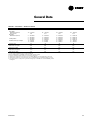
Ta bl e AC - 1 — SXHF, SFHF, SSHF, SLHF —
Panel A and B Dimensions
Total Area (H X W)
Model H (in.) W (in.) (in.
2
) (ft
2
)
S*HF C20 40.7 25.5 1038 7.2
S*HF C25 40.7 25.5 1038 7.2
S*HF C30 52.7 25.5 1344 9.3
S*HF C40 64.5 34.5 2225 15.5
S*HF C50 76.7 34.5 2646 18.4
S*HF C55 76.7 34.5 2646 18.4
S*HF C60 64.6 34.5 2229 15.5
S*HF C70 64.6 34.5 2229 15.5
S*HF C75 64.6 34.5 2229 15.5
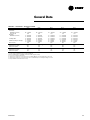
Ta bl e AC -2 — SXHF, SFHF, SSHF, SLHF —
Panel C Dimensions
Total Area (H X W)
Model H (in.) W (in.) (in.
2
) (ft
2
)
S*HF C20 40.7 34.5 1404 9.8
S*HF C25 40.7 34.5 1404 9.8
S*HF C30 52.7 34.5 1818 12.6
S*HF C40 64.5 34.5 2225 15.5
S*HF C50 76.7 34.5 2646 18.4
S*HF C55 76.7 34.5 2646 18.4
S*HF C60 64.6 34.5 2229 15.5
S*HF C70 64.6 34.5 2229 15.5
S*HF C75 64.6 34.5 2229 15.5
* = X, F , L, or S
Ta bl e AC - 3 — SXHF, SFHF, SSHF, SLHF —
X, Y and Z Dimensions
Model X (in.) Y (in.) Z (in.)
S*HF C20 35.5 44.0 201.5
S*HF C25 35.5 44.0 201.5
S*HF C30 35.5 56.0 201.5
S*HF C40 44.5 67.8 237.0
S*HF C50 44.5 80.0 237.0
S*HF C55 44.5 80.0 237.0
S*HF C60 44.5 68.0 237.5
S*HF C70 44.5 68.0 237.5
S*HF C75 44.5 68.0 237.5
Notes:
1. Add an extra 0.20-inches pressure drop to the supply external static to account for the extra turn the air is making.
2. The openings all have a 1.25-inch lip around the perimeter to facilitate ductwork attachment.
3. If exhaust fans are being used, provisions should be made for access to the exhaust components, since the access door is now being used as a return.
4. Use the dimensions provided and the supply Cfm to calculate the velocity (ft/min) through the openings to be sure they are acceptable.
Horizontal Discharge
The typical rooftop installation has both
the supply and return air paths routed
through the roof curb and building roof.
However, many rooftop installations
require horizontal supply and/or return
from the rooftop because of a building’s
unique design or for acoustic
considerations.
Trane has two ways to accomplish
horizontal supply and/or return. The first
applies to all IntelliPak™ Rooftop units.
Special field supplied curbs are installed
that use the unit’s standard discharge
and return openings. The supply and
return air is routed through the curb to
horizontal openings on the sides of the
curb. The second method available for
horizontal supply and return applies to
20 - 75 tons SXHF, SFHF, SLHF, SSHF, and
90 - 130 tons SXHG, SLHG and SSHG
design units ONLY. With this method the
standard discharge and return openings
are blocked in the field. Access panels
are removed as indicated in Figures AC-1
and AC-2. These openings are used for
the discharge and return. No special
curb is needed.
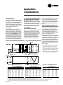
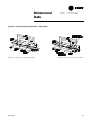
SXHF, SFHF, SLHF, SSHF Units
Figure AC-1 is a simplified sketch of the
rooftop showing which panels can be
used for horizontal supply and/or return.
To supply air horizontally, the panels that
normally house the heat accessory
controls (Panel A) and the gas heat
barometric dampers (Panel B) can be
removed and either of the openings
used as a unit discharge (see note 1). To
return air horizontally, the exhaust fan
access door (Panel C) can be removed
and used as a return opening. Tables AC-
1, 2 and 3 show dimensions for those
panels.
Horizontal Discharge on SXHF, SFHF,
SLHF and SSHF Rooftops (20 to 75 tons)
The SXHF (extended casing cooling
only), SFHF (gas heat), SSHF (steam
heat) and SLHF (hot water heat) rooftops
can be field modified to supply and
return air horizontally without the use of
a horizontal supply/return curb.
To supply air horizontally on SXHF only,
the panels that normally house the heat
accessory controls (Panel A) and the gas
heat barometric dampers (Panel B) can
be removed and either of the openings
used as a unit discharge. To return air
horizontally, the exhaust fan access door
(Panel C) can be removed and used as a
return opening.
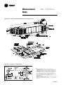
1. For horizontal discharge on SFHF, SLHF and SSHF
units, only the Panel B can be removed. Panel A
cannot be used due to the location of the heating
coils.
2. For horizontal discharge on SFHF (gas heat) models,
the block off under the heater must be removed.
After removal, a support must be added for the drain
tube.
3. Supply and Return Base openings must be covered
when converting to a horizontal configuration.
Note: Cannot remove Panel A
for horizontal discharge on
SFHF, SLHF, SSHF Units.
Figure AC-2 Horizontal Discharge Panel Dimensions — 20 - 75 Tons SXHF, SFHF, SLHF, SSHF Units
Application
Considerations

RT-PRC010-EN12
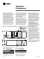
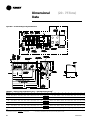
Figure AC-3 is a simplified sketch
showing which panels can be used for
horizontal supply and/or return. On 90 to
130 ton units, only one side of the
extended casing may be used for
horizontal supply because of the
location of the unit control panel. There
are, however, on SXHF models two
panels (Panels A) on the side opposite
the control box which can be removed
along with the vertical support which
separates the two. Removal of the
vertical support is optional, but will
ensure maximum airflow. On SLHG,
SSHG models only one of the Panel A’s
may be used for horizontal supply
because of the location of the heating
coil. Horizontal return is accomplished in
much the same way as on S*HFs by
removing the exhaust fan access door
(Panel B). See Tables AC-4 and 5 for
S*HG panel dimensions.
When using an IntelliPak™ Rooftop for
horizontal supply and return, an
additional pressure drop must be added
to the supply external static to account
for the 90 degree turn the air is making.
This additional pressure drop depends
on airflow and rooftop size, but a range
of 0.10 inches to 0.30 inches can be
expected. The openings on the rooftop
all have a one inch lip around the
perimeter to facilitate ductwork
attachment. If exhaust fans are being
used on an IntelliPak Rooftop unit with
horizontal return, provisions should be
made for access to the exhaust
components, since the access door
opening is now being used as a return.
Perhaps the return ductwork attachment
to the rooftop can include a section of
removable duct. Use the dimensions
provided and the supply and exhaust
CFM to calculate the velocity (ft/min)
through the openings.
Horizontal Discharge SXHG, SLHG,
SSHG Rooftops (90 to 130 tons)
The SXHG, SLHG, SSHG rooftops can be
field modified to supply and return air
horizontally without the use of a
horizontal supply/return curb.
To supply air horizontally, use Panel A
only. The Panel on the opposite side
cannot be used due to the location of the
unit control Panel. SXHG rooftop air
conditioners do not have a panel
configuration like the 20 to 75 ton
rooftops. To achieve maximum airflow,
vertical support can be removed after the
unit has been placed on the roof curb. It
is secured by four screws. (See Note 1)
For horizontal discharge on SLHG and
SSHG units, only the Panel A next to the
condenser fan section can be removed.
The other Panel A next to the supply fan
cannot be used due to the location of the
heating coils.
To return air horizontally, the exhaust fan
access door (Panel B) can be removed
and used as a return opening.
Table AC-4 — SXHG, SLHG, SSHG —
Panel A and B Dimensions
Total Area (H X W)
Panel H (in.) W (in.) (in.
2
) (ft
2
)
A 72.7 27.5 1999 13.9
B 72.7 34.5 2508 17.4
Notes:
1. Add an extra 0.20-inches pressure drop to the
supply external static to account for the extra turn
the air is making.
2. The openings all have a 1.25-inch lip around the
perimeter to facilitate ductwork attachment.
Table AC-5 — SXHG, SLHG, SSHG —
X, Y and Z Dimensions
Model X (in.) Y (in.) Z (in.)
S*HG 90-130 69.0 77.8 244.7
* = X, L, or S
Note:
1. SXHG units have two Panel A’s that can be removed. Once unit is installed, panel(s) and the 6
1
/2” vertical
support channel in between may be removed.
3. If exhaust fans are being used, provisions should
be made for access to the exhaust components,
since the access door is now being used as a
return.
4. Use the dimensions provided and the supply Cfm
to calculate the velocity (ft/min) through the
openings to be sure they are acceptable.
Figure AC-3 — Horizontal Discharge Panel Dimensions — 90 - 130 Tons SXHG, SLHG, SSHG Units
Application
Considerations

13RT-PRC010-EN
High Capacity Evaporator Coil
Rooftops are popular because of their
“packaged” nature. Everything needed
is contained in one box; mix-matching is
neither necessary nor available. With this
convenience comes some
disadvantages; one is the rooftop’s
cooling capacity may not exactly match
the building load. It is conceivable that a
50 ton rooftop would need to be used on
an application that is 41 tons, simply
because the 40 ton rooftop does not
meet capacity.
In order to avoid such occurrences, and
to more closely match the rooftop’s
capacity to the building load, a high
capacity evaporator coil option is
available on all IntelliPak™ Rooftops 20
to 105 tons. These high capacity coils
have an increased number of evaporator
coil rows as compared to standard and
enhanced evaporator tube surfaces,
resulting in a higher capacity. Capacity
tables for both standard and high
capacity coils are available in the cooling
data section of this catalog. See Table
PD-43 for the pressure drops associated
with the high capacity coil option. This
pressure drop should be added to the
total static pressure used to size the
supply fan motor.
Low Ambient Operation — Human
Interface Recommendations
Who wants to be on a roof at sub-zero
temperatures? We can understand a
service technician’s reluctance to do this;
that’s why we recommend using a
remote mounted Human Interface Panel.
The service technician can troubleshoot
and diagnose in the comfort of a
mechanical room.
Corrosive Atmospheres
Trane’s IntelliPak Rooftops are designed
and built to industrial standards and will
perform to those standards for an
extended period depending on the hours
of use, the quality of maintenance
performed, and the regularity of that
maintenance. One factor that can have
an adverse effect on unit life is its
operation in a corrosive environment.
When rooftops are operated in corrosive
environments, Trane recommends that
copper fins be utilized on the condenser
and/or evaporator coil. Because copper
is more resistant to corrosion than
aluminum, coil life expectancy is greatly
increased. Some industry applications
expose equipment to corrosive agents
that even copper cannot fully resist. For
those special applications, a baked
phenolic resin coating (i.e. Heresite) is
highly desirable. Baked phenolic
coatings or copper fins on the condenser
and/or evaporator coils are available on
Trane’s IntelliPak Rooftops.
Ventilation Override Sequences
One of the benefits of using an exhaust
fan rather than a return fan, in addition
to the benefits of lower energy usage
and improved building pressurization
control, is that the rooftop can be used
as part of a ventilation override system.
Several types of sequences can be easily
done when exhaust fans are a part of the
rooftop system.
What would initiate the ventilation
override control sequence? Typically, a
manual switch is used and located near
the fire protection control panel. This
enables the fire department access to the
control for use during or after a fire. It is
also possible to initiate the sequence
from a field-installed automatic smoke
detector. In either case, a contact closure
begins the ventilation override control
sequence. CAUTION!: The ventilation
override system should not be used to
signal the presence of smoke caused by
a fire.
Trane can provide five (5) different
ventilation override sequences on both
CV and VAV IntelliPak Rooftops. For your
convenience the sequences can be
factory preset or fully field editable from
the Human Interface Panel or Tracer™.
Any or all five sequences may be
“locked” in by the user at the Human
Interface Panel.
The user can customize up to five (5)
different override sequences for
purposes such as smoke control. The
following parameters within the unit can
be defined for each of the five
sequences:
• Supply Fan — on/off
• Inlet Guide Vanes — open/closed/
controlling
• Variable Frequency Drives — on (60
Hz)/off (0 Hz)/controlling
• Exhaust Fan — on/off
• Exhaust Dampers — open/closed
• Economizer dampers — open/closed
• Heat — off/controlling (output for) VAV
Boxes — open/controlling
Compressors and condenser fans are
shut down for any Ventilation Override
sequence. Factory preset sequences
include unit Off, Exhaust, Purge, Purge
with duct pressure control, and
Pressurization. Any of the user-defined
Ventilation Override sequences can be
initiated by closing a field supplied
switch or contacts connected to an input
on the Ventilation Override Module. If
more than one ventilation override
sequence is being requested, the
sequence with the highest priority is
initiated. Refer to the Sequence of
Operation provided in the Control
section of this catalog for more details
on each override sequence.
Natural Gas Heating Considerations
The IntelliPak standard, or limited
modulation, gas heat exchangers are not
recommended for applications with
mixed air conditions entering the heat
exchanger below 50°F. Mixed air
temperatures below 50°F can cause
condensation to form on the heat
exchanger, leading to premature failure.
Application
Considerations

RT-PRC010-EN14
For increased reliability, the
recommendation in these applications is
full modulation gas heat. For airflow
limitations and temperature rise across
the heat exchanger information, see
Table PD-24, 25 and RT-EB-104.
Acoustical Considerations
The ideal time to make provisions to
reduce sound transmission to the space
is during the project design phase.
Proper placement of rooftop equipment
is critical to reducing transmitted sound
levels to the building. The most
economical means of avoiding an
acoustical problem is to place any
rooftop equipment away from
acoustically critical area. If possible,
rooftop equipment should not be located
directly above areas such as: offices,
conference rooms, executive office areas
and classrooms. Ideal locations are
above corridors, utility rooms, toilet
facilities, or other areas where higher
sound levels are acceptable.
Several basic guidelines for unit
placement should be followed to
minimize sound transmission through
the building structure:
1
Never cantilever the condensing section
of the unit. A structural cross member
must support this end of the unit.
2
Locate the unit’s center of gravity close
to or over a column or main support
beam to minimize roof deflection and
vibratory noise.
3
If the roof structure is very light, roof
joists should be replaced by a structural
shape in the critical areas described
above.
4
If several units are to be placed on one
span, they should be staggered to
reduce deflection over that span.
It is impossible to totally quantify the
effect of building structure on sound
transmission, since this depends on the
response of the roof and building
members to the sound and vibration of
the unit components. However, the
guidelines listed above are experience
proven guidelines which will help reduce
sound transmission.
There are several other sources of unit
sound, i.e., supply fan, compressors,
exhaust fans, condenser fans and
aerodynamic noise generated at the duct
fittings. Refer to the ASHRAE
Applications Handbook, Chapter 42, 1991
edition for guidelines for minimizing the
generation of aerodynamic noise
associated with duct fittings.
Trane’s Engineering Bulletin RT-EB-80
describes various duct installation
considerations specifically addressing
indoor sound level concerns. This
bulletin includes sound power data on
Trane’s IntelliPak Rooftops 20 to 130 tons.
Ask your local Trane representative for
this informative engineering bulletin.
The VariTrane™ Computerized Duct
Design Program can be used to analyze
the truck duct, run-out duct, VAV control
unit and terminal unit noise attenuation.
This program quantifies the airborne
sound generation that can be expected
in each terminal so that the designer can
identify potential sound problems and
make design alterations before
equipment installation.
The Trane Acoustics Program (TAP)
allows modeling of rooftop installation
parameters. The output of this program
shows the resulting indoor NC level for
the modeled installation. This program is
available from Trane’s Customer Direct
Service Network™ (C.D.S.), ask your
local Trane representative for additional
information on this program.
Clearance Requirements
The recommended clearances identified
with unit dimensions should be
maintained to assure adequate
serviceability, maximum capacity and
peak operating efficiency. A reduction in
unit clearance could result in condenser
coil starvation or warm condenser air
recirculation. If the clearances shown are
not possible on a particular job, consider
the following:
• Do the clearances available allow for
major service work such as changing
compressors or coils?
• Do the clearances available allow for
proper outside air intake, exhaust air
removal and condenser airflow?
• If screening around the unit is being
used, is there a possibility of air
recirculation from the exhaust to the
outside air intake or from condenser
exhaust to condenser intake?
Actual clearances which appear
inadequate should be reviewed with a
local Trane sales engineer.
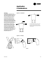
When two or more units are to be placed
side by side, the distance between the
units should be increased to 150 percent
of the recommended single unit
clearance. The units should also be
staggered as shown in Figure AC-4 for
two reasons:
1
To reduce span deflection if more than
one unit is placed on a single span.
Reducing deflection discourages sound
transmission.
2
To assure proper diffusion of exhaust air
before contact with the outside air intake
of adjacent unit.
Application
Considerations

15RT-PRC010-EN
Duct Design
It is important to note that the rated
capacities of the rooftop can be met only
if the rooftop is properly installed in the
field. A well-designed duct system is
essential in meeting these capacities.
The satisfactory distribution of air
throughout the system requires that
there be an unrestricted and uniform
airflow from the rooftop discharge duct.
This discharge section should be straight
for at least several duct diameters to
allow the conversion of fan energy from
velocity pressure to static pressure.
However, when job conditions dictate
elbows be installed near the rooftop
outlet, the loss of capacity and static
pressure may be reduced through the
use of guide vanes and proper direction
of the bend in the elbow. The high
velocity side of the rooftop outlet should
be directed at the outside radius of the
elbow rather than the inside as
illustrated in Figure AC-5.
Figure AC-4 — Unit Placement
Figure AC-5 — Duct Design
1. 20-40 ton models have only one outdoor air intake.
50 - 75 ton models have two outdoor air intakes.
2. 90-130 ton models have two outdoor air intakes on
the backside of the unit and one small air intake at
the end of the unit.
Proper
Improper
1
2
Application
Considerations

RT-PRC010-EN16
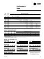
Selection
Procedure
This section outlines a step-by-step
procedure that may be used to select a
Trane single-zone air conditioner. The
sample selection is based on the
following conditions:
• Summer outdoor design conditions —
95 DB/76 WB ambient temperature
• Summer room design conditions —78
DB/65 WB
• Total cooling load — 430 MBh (35.8
tons)
• Sensible cooling load — 345 MBh (28.8
tons)
• Outdoor air ventilation load — 66.9
MBh
• Return air temperature — 80 DB/65 WB
Winter Design:
• Winter outdoor design conditions —0 F
• Return air temperature — 70 F
• Total heating load — 475 MBh
• Winter outdoor air ventilation load —
133 MBh
Air Delivery Data:
• Supply fan cfm — 17,500 cfm
• External static pressure — 1.2 in wg
• Minimum outdoor air ventilation —
1,750 cfm
• Exhaust fan cfm — 12,000 cfm
• Return air duct negative static pressure
— 0.65 in wg
Electrical Characteristics:
• Voltage/cycle/phase — 460/60/3 Unit
Accessories:
• Gas fired heat exchanger — high heat
module
• Throwaway filters
• Economizer
• Modulating 100 percent exhaust/
return fan
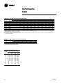
COOLING CAPACITY SELECTION
Step 1 — Nominal Unit Size Selection
A summation of the peak cooling load
and the outside air ventilation load
shows: 430 MBh + 66.9 MBh = 496.9
MBh required unit capacity. From
Table PD-9, a 50 ton unit capacity with
standard capacity evaporator coil at
80 DB/65 WB, 95 F outdoor air
temperature and 17,500 total supply cfm
is 551 MBh total and 422 MBh sensible.
Thus, a nominal 50 ton unit with
standard capacity evaporator coil
is selected.
Step 2 — Evaporator Coil Entering
Conditions
Mixed air dry bulb temperature
determination:
Using the minimum percent of OA (1,750
cfm ÷ 17,500 cfm = 10 percent),
determine the mixture dry bulb to the
evaporator.
RADB + % OA (OADB - RADB) = 80 +
(0.10) (95 - 80) = 80 + 1.5 = 81.5 F
Approximate wet bulb mixture
temperature:
RAWB + % OA (OAWB - RAWB) = 65 +
(0.10) (76 - 65) = 65 + 1.1 = 66.1 F
Step 3 — Determine Supply Fan Motor
Heat Gain
Having selected a nominal 50 ton unit,
the supply fan bhp can be calculated. The
supply fan motor heat gain must be
considered in final determination of unit
capacity.
Supply Air Fan
Determine unit total static pressure at
design supply cfm:
External Static Pressure 1.2 inches
Evaporator Coil 0.25 inches
(Table PD-43)
Return Duct Negative 0.65 inches
Static Pressure
Heat Exchanger 0.31 inches
(Table PD-43)
Throwaway Filter 0.10 inches
(Table PD-43)
Economizer w/Exhaust Fan 0.12 inches
(Table PD-43)
Trane Roof Curb 0.13 inches
(Table PD-43)
Unit Total Static Pressure 2.76 inches
Using total of 17,500 cfm and total
static pressure of 2.76 inches, enter Table
PD-36. Table PD-36 shows 15.3 bhp with
924 rpm.
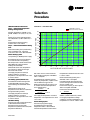
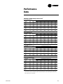
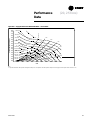
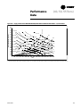
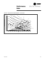
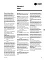
From Chart SP-1 supply fan motor heat
gain = 46.0 MBh.
Step 4 — Determine Total Required
Cooling Capacity
Required capacity = Total peak load + OA
load + supply air fan motor heat.
Required capacity = 430 + 66.9 +
46.0 = 543 MBh (45.2 tons)
Step 5 — Determine Unit Capacity
From Table PD-9, unit capacity at 81.5 DB/
66.1 WB entering the evaporator, 17,500
supply air cfm, 95 F outdoor ambient, is
561 MBh (45.8 tons) with 426 MBh
sensible.
Step 6 — Determine Leaving Air
Temperature
Unit sensible heat capacity corrected for
supply air fan motor heat = 426 MBh - 46
MBh = 380 MBh.
Supply air dry bulb temperature
difference =
Sensible Btu =
1.085 x Supply cfm
380 MBh ÷ (1.085 x 17,500 cfm)
= 20.0 F
Supply air dry bulb = 81.5 DB - 20.0
= 61.5 F
Unit enthalpy difference =
Total Btu =
4.5 x Supply cfm
561 MBh ÷ (4.5 x 17,500 cfm) =
7.12 Btu/lb
Leaving enthalpy = h(ent WB) -
h(diff). From Table 21-1 h(ent WB) =
30.9 Btu/lb
Leaving enthalpy = 30.9 Btu/lb - 7.12
Btu/lb = 23.78 Btu/lb
Supply air wet bulb = 55.9
Leaving air temperature = 61.5
DB/55.9 WB

17RT-PRC010-EN
Selection
Procedure
ITD = 190 F - 65.4 F = 125 F. Divide the
winter heating load by ITD = 563 MBh ÷
125 F = 4.50 Q/ITD.
From Table PD-31, select the low heat
module. By interpolation, a Q/ITD of 4.50
can be obtained at a gpm at 25.7.
Water pressure drop at 25.7 gpm is 0.57
ft. of water. Heat module temperature
rise is determined by:
Total Btu = ∆T
1.085 x Supply cfm
563,000 = 29.7 F
(1.085 x 17,500)
Unit supply air temperature = mixed air
temperature + air temperature rise = 65.4
+ 29.7 = 95 F.
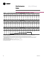
Steam Heating System
Assume a 15 psig steam supply.
From Table PD-27, the saturated
temperature steam is 250 F. Subtract
mixed air temperature from the steam
HEATING CAPACITY SELECTION
Step 1 — Determine Air Temperature
Entering Heating Module
Mixed air temperature = RADB + % OA
(OADB - RADB) = 70 + (0.10) (0 - 70) = 63
F
Supply air fan motor heat temperature
rise = 46,000 Btu ÷ (1.085 x 17,500 cfm) =
2.42 F
Air temperature entering heating
module = 63.0 + 2.42 = 65.4 F
Step 2 — Determine Total Winter Heating
Load
Total winter heating load = peak heating
load + ventilation load - supply fan
motor heat = 475 + 133 - 46.0 = 562 MBh
Electric Heating System
Unit operating on 460/60/3 power supply.
From Table PD-30, kw may be selected
for a nominal 50 ton unit operating
460-volt power. The 170 kw heat module
(580.1 MBh) will satisfy the winter
heating load of 563 MBh.
Table PD-28 shows an air temperature
rise of 30.6 F for 17,500 cfm through
the 170 kw heat module.
Unit supply temperature at design
heating conditions = mixed air
temperature + air temperature rise = 65.4
F + 30.6 F = 96.0 F.
Gas Heating System (Natural Gas)
From Table PD-24 select the high heat
module (697 MBh output) to satisfy
winter heating load of 563 MBh at unit
cfm.
Table PD-26 also shows an air
temperature rise of 36.0 F for 17,500 cfm
through the heating module.
Unit supply temperature at design
heating conditions = mixed air
temperature + air temperature rise = 65.4
F + 36.0 F = 101.4 F.
Hot Water Heating
Assume a hot water supply temperature
of 190 F. Subtract the mixed air
temperature from the hot water
temperature to determine the ITD (initial
temperature difference).
temperature to determine ITD. ITD = 250
F - 65.4 F = 185 F.
Divide winter heating load by ITD =
563 MBh ÷ 185 F = 3.04 Q/ITD.
From Table PD-26, select the high heat
module. The high heat module at 17,500
cfm has a Q/ITD = 5.11.
Heat module capacity, Q = ITD x Q/ITD =
185 F x 5.11 Q/ITD = 945 MBh
Heat module air temperature rise
=
Total Btu
1.085 x Supply cfm
945 Btu ÷ (1.085 x 17,500 cfm) = 49.8 F.
Unit supply temperature at design
conditions = mixed air temperature + air
temperature rise = 65.4 F + 49.8 F = 115 F.
Chart SP-1 — Fan Motor Heat
0 5 10 15 20 25 30 35 40
0
10
20
30
40
50
60
70
80
90
100
110
120
STANDARD MOTOR
HIGH EFFICIENCY MOTOR
FAN MOTOR HEAT - MBH
MOTOR BRAKE HORSE POWER

RT-PRC010-EN18
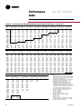
AIR DELIVERY PROCEDURE
Supply fan performance tables include
internal resistance of rooftop. For total
static pressure determination, system
external static must be added to
appropriate component static pressure
drop (evaporator coil, filters, optional
economizer, optional exhaust fan,
optional heating system, optional
cooling only extended casing, optional
roof curb).
Supply Fan Motor Sizing
The supply fan motor selected in the
cooling capacity determination was 15.3
bhp and 924 rpm. Thus, a 20 hp supply
fan motor is selected. Enter Table PD-45
to select the proper drive. For a 50 ton
rooftop with 20 hp motor, a drive
number 9 — 900 rpm is selected.
Exhaust Fan Motor Sizing
The exhaust fan is selected based on
total return system negative static
pressure and exhaust fan cfm. Return
system negative static include return
duct static and roof curb static pressure
drop.
Return duct static pressure = 0.65 inches
Trane roof curb (Table PD-43) = 0.12
inches
Total return system negative static
pressure = 0.77 inches
Exhaust fan cfm = 12,000 cfm
From Table PD-47, the required bhp is
3.45 hp at 574 rpm. Thus, the exhaust fan
motor selected is 5 hp.
To select a drive, enter Table PD-49 for a 5
hp motor for a 50 ton unit. Drive
selection number 6 — 600 rpm.
Where altitudes are significantly above
sea level, use Tables PAF-2 and PAF-3 and
Figure PAF-1 for applicable correction
factors.
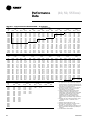
UNIT ELECTRICAL REQUIREMENTS
Selection procedures for electrical
requirements for wire sizing amps,
maximum fuse sizing, and dual element
fuses are given in the electrical service
section of this catalog.
Altitude Corrections
The rooftop performance tables and
curves of this catalog are based on
standard air (.075 lbs/ft). If the rooftop
airflow requirements are at other than
standard conditions (sea level), an air
density correction is needed to project
accurate unit performance.
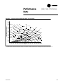
Figure PAF-1 shows the air density ratio
at various temperatures and elevations.
Trane rooftops are designed to operate
between 40 and 90 degrees Fahrenheit
leaving air temperature.
The procedure to use when selecting a
supply or exhaust fan on a rooftop for
elevations and temperatures other than
standard is as follows:
1
First, determine the air density ratio
using Figure PAF-1.
2
Divide the static pressure at the
nonstandard condition by the air
density ratio to obtain the corrected
static pressure.
3
Use the actual cfm and the corrected
static pressure to determine the fan rpm
and bhp from the rooftop performance
tables or curves.
4
The fan rpm is correct as selected.
5
Bhp must be multiplied by the air
density ratio to obtain the actual
operating bhp.
Selection
Procedure

19RT-PRC010-EN
Selection
Procedure
In order to better illustrate this
procedure, the following example is
used:
Consider a 60 ton rooftop unit that is to
deliver 18,000 actual cfm at 3-inches total
static pressure (tsp), 55 F leaving air
temperature, at an elevation of 5,000 ft.
1
From Figure PAF-1, the air density ratio is
0.86.
2
Tsp = 3.0-inches / 0.86 = 3.49 inches tsp.
3
From the performance tables: a 60 ton
rooftop (without inlet vanes) will deliver
18,000 cfm at 3.49-inches tsp at 906 rpm
and 21.25 bhp.
4
The rpm is correct as selected - 906 rpm.
5
Bhp = 21.25 x 0.86 = 18.3 bhp actual.
Compressor MBh, SHR, and kw should
be calculated at standard and then
converted to actual using the correction
factors in Table PAF-2. Apply these factors
to the capacities selected at standard cfm
so as to correct for the reduced mass
flow rate across the condenser.
Heat selections other than gas heat will
not be affected by altitude. Nominal gas
capacity (output) should be multiplied by
the factors given in Table PAF-3 before
calculating the heating supply air
temperature.
HEATING CAPACITY SELECTION
Step 1 — Determine Air Temperature
Entering Heating Module
Mixed air temperature = RADB + % OA
(OADB - RADB) = 70 + (0.10) (0 - 70) = 63
F
Supply air fan motor heat temperature
rise = 46,000 Btu ÷ (1.085 x 17,500 cfm) =
2.42 F
Air temperature entering heating
module = 63.0 + 2.42 = 65.4 F

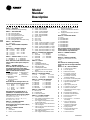
RT-PRC010-EN20
Model
Number
Description
DIGIT 1 — UNIT TYPE
S = Self-Contained (Packaged Rooftop)
DIGIT 2 — UNIT FUNCTION
A = DX Cooling, No Heat
E = DX Cooling, Electric Heat
F = DX Cooling, Natural Gas Heat
L = DX Cooling, Hot Water Heat
S = DX Cooling, Steam Heat
X = DX Cooling, No Heat, Extended Casing
DIGIT 3 — UNIT AIRFLOW
H = Single Zone
DIGIT 4 — DEVELOPMENT SEQUENCE
F = Sixth
DIGITS 5,6,7 — NOMINAL CAPACITY
C20 = 20 Tons C55 = 55 Tons
C25 = 25 Tons C60 = 60 Tons
C30 = 30 Tons C70 = 70 Tons
C40 = 40 Tons C75 = 75 Tons
C50 = 50 Tons
DIGIT 8 — POWER SUPPLY (See Notes)
4 = 460/60/3 XL E = 200/60/3 XL
5 = 575/60/3 XL F = 230/60/3 XL
Note: SEHF units (units with electric heat)
utilizing 208V or 230V require dual power
source.
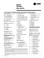
DIGIT 9 — HEATING CAPACITY
Note: When the second digit calls for “F”
(Gas Heat), the following values apply:
Additionally, please note G and M available
ONLY on 50 Ton models and above.
H = High Heat-2-Stage P = High Heat-Full
L = Low Heat-2-Stage Modulation
0 = No Heat M = Low Heat-Full
J = High Heat-Limited Modulation
Modulation
G = Low Heat-Limited
Modulation
Note: When the second digit calls for “E”
(electric heat), the following values apply:
D = 30 KW R = 130 KW
H = 50 KW U = 150 KW
L = 70 KW V = 170 KW
N = 90 KW W = 190 KW
Q = 110 KW
Note: When the second digit calls for ‘’L’’
(Hot Water) or ‘’S’’(Steam) Heat, one of the
following valve size values must be in Digit 9:
High Heat Coil: 1 = .50”, 2 = .75”, 3 = 1”,
4 = 1.25”, 5 = 1.5”, 6 = 2”.
Low Heat Coil: A = .50”, B = .75”, C = 1”,
D = 1.25”, E = 1.5”, F = 2”.
DIGIT 10 — DESIGN SEQUENCE
A = First (Factory Assigned)
Note: Sequence may be any letter A thru Z,
or any digit 1 thru 9.
DIGIT 11 — EXHAUST OPTION
0 = None
1 = Barometric
2 = 100%, 1.5 HP W/Statitrac
3 = 100%, 3 HP W/Statitrac
4 = 100%, 5 HP W/Statitrac
5 = 100%, 7.5 HP W/Statitrac
6 = 100%, 10 HP W/Statitrac
7 = 100%, 15 HP W/Statitrac
8 = 100%, 20 HP W/Statitrac
A = 50%, 1.5 HP
B = 50%, 3 HP
C = 50%, 5 HP
D = 50%, 7.5 HP
E = 100%, 1.5 HP W/O Statitrac (CV Only)
F = 100%, 3 HP W/O Statitrac (CV Only)
G = 100%, 5 HP W/O Statitrac (CV Only)
H = 100%, 7.5 HP W/O Statitrac (CV Only)
J = 100%, 10 HP W/O Statitrac (CV Only)
K = 100%, 15 HP W/O Statitrac (CV Only)
L = 100%, 20 HP W/O Statitrac (CV Only)
DIGIT 12 — EXHAUST AIR FAN DRIVE
0 = None 8 = 800 RPM
4 = 400 RPM 9 = 900 RPM
5 = 500 RPM A = 1000 RPM
6 = 600 RPM B = 1100 RPM
7 = 700 RPM
DIGIT 13 — FILTER
A = Throwaway
B = Cleanable Wire Mesh
C = High-Efficiency Throwaway
D = Bag With Prefilter
E = Cartridge With Prefilter
F = Throwaway Filter Rack Less Filter
Media
G = Bag Filter Rack Less Filter Media
DIGIT 14 — SUPPLY AIR FAN HP
1 = 3 HP 4 = 10 HP 7 = 25 HP
2 = 5 HP 5 = 15 HP 8 = 30 HP
3 = 7.5 HP 6 = 20 HP 9 = 40 HP
3
DIGIT 15 — SUPPLY AIR FAN DRIVE
5 = 500 RPM B = 1100 RPM
6 = 600 RPM C = 1200 RPM
7 = 700 RPM D = 1300 RPM
8 = 800 RPM E = 1400 RPM
9 = 900 RPM F = 1500 RPM
A= 1000 RPM G = 1600 RPM
DIGIT 16 — FRESH AIR
A = No Fresh Air
B = 0-25% Manual
D = 0-100% Economizer
DIGIT 17 — SYSTEM CONTROL
1 = Constant Volume Control
2 = VAV Supply Air Temperature Control
w/o Inlet Guide Vanes
3 = VAV Supply Air Temperature Control
w/ Inlet Guide Vanes
4 = Space Pressure Control with Exhaust
VFD w/o Bypass
5 = Space Pressure Control with Exhaust
VFD and Bypass
6 = VAV Supply Air Temperature Control
with VFD w/o Bypass
7 = VAV Supply Air Temperature Control
with VFD and Bypass
8 = Supply and Exhaust Fan with VFD
w/o Bypass
9 = Supply and Exhaust Fan with VFD
and Bypass
DIGIT 18 — ACCESSORY PANEL
0 = None
A = BAYSENS008*
B = BAYSENS010*
C = BAYSENS013*
D = BAYSENS014*
E = BAYSENS019*
F = BAYSENS020*
G = BAYSENS021*
Note: *Asterisk indicates current model
number digit A, B, C, etc. These sensors
can be ordered to ship with the unit.
DIGIT 19 — AMBIENT CONTROL
0 = Standard
1 = 0° Fahrenheit
DIGIT 20 — AGENCY APPROVAL
0 = None (UL Gas Heater, see note)
1 = UL
2 = CSA
Note: Includes UL classified gas heating
section only when second digit of Model No.
is a “F.”
DIGITS 21 - 38 — MISCELLANEOUS
21 A = Unit Disconnect Switch
22 B = Hot Gas Bypass
23 0 = Without Economizer
C = Economizer Control w/
Comparative Enthalpy
23 Z = Economizer Control w/
Reference Enthalpy
23 W = Economizer Control w/Dry Bulb
24 E = Low Leak Fresh Air Dampers
25 F = High Duct Temperature
Thermostat
26 G = High Capacity Evap. Coil
27 H = Copper Fins (Cond. Only)
28 K = Generic B.A.S. Module
29 L = High-Efficiency Motors (Supply
and Exhaust)
30 M = Remote Human Interface
31 N = Ventilation Override Module
32 R = Extended Grease Lines
33 T = Access Doors
34 V = Inter-Processor Communica
tion Bridge
35 Y = Trane Communication
Interface (TCI) Module
35 7 = LonTalk Communication
Interface (LCI) Module
36 8 = Spring Isolators
37 6 = Factory-Powered 15A GFI
Convenience Outlet
38 5 = VFD Line Reactor
S F H F C 5 5 F H A 5 5 C 6 9 D 3 0 0 1 0 0 0 0 0 0 0 0 0 0 0 0 0 0 0 0 0 0
1
1 2 3 4 5 6 7 8 9 101112131415161718192021222324252627 28 29 30 31 32 33 34 35 36 37 38
Page is loading ...
Page is loading ...
Page is loading ...
Page is loading ...
Page is loading ...
Page is loading ...
Page is loading ...
Page is loading ...
Page is loading ...
Page is loading ...
Page is loading ...
Page is loading ...
Page is loading ...
Page is loading ...
Page is loading ...
Page is loading ...
Page is loading ...
Page is loading ...
Page is loading ...
Page is loading ...
Page is loading ...
Page is loading ...
Page is loading ...
Page is loading ...
Page is loading ...
Page is loading ...
Page is loading ...
Page is loading ...
Page is loading ...
Page is loading ...
Page is loading ...
Page is loading ...
Page is loading ...
Page is loading ...
Page is loading ...
Page is loading ...
Page is loading ...
Page is loading ...
Page is loading ...
Page is loading ...
Page is loading ...
Page is loading ...
Page is loading ...
Page is loading ...
Page is loading ...
Page is loading ...
Page is loading ...
Page is loading ...
Page is loading ...
Page is loading ...
Page is loading ...
Page is loading ...
Page is loading ...
Page is loading ...
Page is loading ...
Page is loading ...
Page is loading ...
Page is loading ...
Page is loading ...
Page is loading ...
Page is loading ...
Page is loading ...
Page is loading ...
Page is loading ...
Page is loading ...
Page is loading ...
Page is loading ...
Page is loading ...
Page is loading ...
Page is loading ...
Page is loading ...
Page is loading ...
Page is loading ...
Page is loading ...
Page is loading ...
Page is loading ...
Page is loading ...
Page is loading ...
Page is loading ...
Page is loading ...
Page is loading ...
Page is loading ...
Page is loading ...
Page is loading ...
Page is loading ...
Page is loading ...
Page is loading ...
Page is loading ...
-
 1
1
-
 2
2
-
 3
3
-
 4
4
-
 5
5
-
 6
6
-
 7
7
-
 8
8
-
 9
9
-
 10
10
-
 11
11
-
 12
12
-
 13
13
-
 14
14
-
 15
15
-
 16
16
-
 17
17
-
 18
18
-
 19
19
-
 20
20
-
 21
21
-
 22
22
-
 23
23
-
 24
24
-
 25
25
-
 26
26
-
 27
27
-
 28
28
-
 29
29
-
 30
30
-
 31
31
-
 32
32
-
 33
33
-
 34
34
-
 35
35
-
 36
36
-
 37
37
-
 38
38
-
 39
39
-
 40
40
-
 41
41
-
 42
42
-
 43
43
-
 44
44
-
 45
45
-
 46
46
-
 47
47
-
 48
48
-
 49
49
-
 50
50
-
 51
51
-
 52
52
-
 53
53
-
 54
54
-
 55
55
-
 56
56
-
 57
57
-
 58
58
-
 59
59
-
 60
60
-
 61
61
-
 62
62
-
 63
63
-
 64
64
-
 65
65
-
 66
66
-
 67
67
-
 68
68
-
 69
69
-
 70
70
-
 71
71
-
 72
72
-
 73
73
-
 74
74
-
 75
75
-
 76
76
-
 77
77
-
 78
78
-
 79
79
-
 80
80
-
 81
81
-
 82
82
-
 83
83
-
 84
84
-
 85
85
-
 86
86
-
 87
87
-
 88
88
-
 89
89
-
 90
90
-
 91
91
-
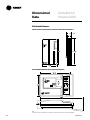 92
92
-
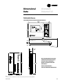 93
93
-
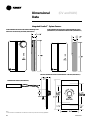 94
94
-
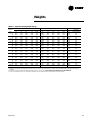 95
95
-
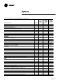 96
96
-
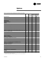 97
97
-
 98
98
-
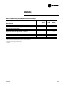 99
99
-
 100
100
-
 101
101
-
 102
102
-
 103
103
-
 104
104
-
 105
105
-
 106
106
-
 107
107
-
 108
108


Trane IntelliPak SXHF C50 User manual
- Category
- Heat pumps
- Type
- User manual
Ask a question and I''ll find the answer in the document
Finding information in a document is now easier with AI
Related papers
-
Trane IntelliPak SXHF C50 User manual
-
-
Trane RT-PRC010-EN User manual
-
-
-
-
-
-
-
Trane IntelliPak Signature SCRF-029 Programming Manual
Other documents
-
Pyle PDWM2560 User manual
-
Electrolux ESF97400RKX User guide
-
Electrolux IHGL150X User manual
-
Electrolux IHGL1260CN Installation guide
-
-
-
-
-
Electrolux IHSL1060CN Installation guide
-
Dataflex 54.352 Datasheet