Page is loading ...

sec.2c
−−−−
1
II ED
.
V
O
P
BIBUS 2
nd
Ed. VOP - Technical Manual
KOMBI
CALL MODULE
SECTION 2c
Download from:
www.urmetdomus.com
Technical Manuals area

CONTENTS BIBUS II^ Ed. VOP SYSTEM - Section 2c
SECTION 2c CONTENTS
BIBUS II^ Ed. VOP SYSTEM
sec.2c
−−−−
I
II ED
.
V
O
P
BIBUS 2
nd
Ed. VOP - Technical Manual
Sec. Pag.
KOMBI CALL MODULE
KOMBI CALLING MODULE WITH REPERTORY Ref. 1072/12
PERFORMANCE.................................................................................................................................................................................. 2c ................3
STRUCTURE ....................................................................................................................................................................................... 2c ................3
DESCRIPTION OF TERMINALS AND CONNECTORS ...................................................................................................................... 2c ................4
TECHNICAL SPECIFICATIONS .......................................................................................................................................................... 2c ................4
OPERATION ........................................................................................................................................................................................ 2c ................4
Calls to users.................................................................................................................................................................................... 2c ................4
Direct call to concierge switchboard ................................................................................................................................................. 2c ................5
Door opener codes ........................................................................................................................................................................... 2c ................5
Busy function .................................................................................................................................................................................... 2c ................5
PROGRAMMING.................................................................................................................................................................................. 2c ................6
Programming via 1032/65 keyboard................................................................................................................................................. 2c ................6
Programming via local keypad.......................................................................................................................................................... 2c ................6
Programming parameters................................................................................................................................................................. 2c ................6
Default settings................................................................................................................................................................................. 2c ............. 10
Programming via PC ........................................................................................................................................................................ 2c ............. 10
ADDITIONAL INFORMATION.............................................................................................................................................................. 2c ............. 10
VOLUME ADJUSTMENT ..................................................................................................................................................................... 2c ............. 10
DISPLAY CONTRAST REGULATION ................................................................................................................................................. 2c ............. 10
ADDITIONAL ALPHABETIC KEYBOARD Ref. 1038/72 ...................................................................................................................... 2c ............. 10
INSTALLATION.................................................................................................................................................................................... 2c ............. 11
Flush-mounted version ..................................................................................................................................................................... 2c ............. 11
Wall-mounted version with case and hood....................................................................................................................................... 2c ............. 11
ACCESSORY INSTALLATION ........................................................................................................................................................... 2c ............. 11
Flush-mounted version with wall cover frame................................................................................................................................... 2c ............. 11
Flush-mounted version with rain hood.............................................................................................................................................. 2c ............. 11
Examples of modular constructions.................................................................................................................................................. 2c ............. 12

sec.2c
−−−−
3
KOMBI CALL MODULE
II ED
.
V
O
P
BIBUS 2
nd
Ed. VOP - Technical Manual
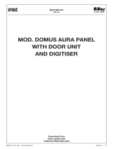
KOMBI CALLING MODULE WITH REPERTORY
Ref. 1072/12
The 1072/12 calling module corresponds to 2 Kombi modules and
is provided with back-lit 16x2 character display, built-in door unit
and back-lit buttons. Flush-mounting boxes or cases with hood and
respective module holders and accessories are required for installation
(see “Installation” section).
The 2nd edition 1072/12 calling module with repertory can be used
both in new installations and for retrofi tting old 1st edition systems.
NOTE: Systems are called “2nd edition” (and consequently offer
BIBUS 2nd edition performance) when all devices in the
system are 2nd edition devices and confi gured as such.
PERFORMANCE
The calling module with repertory Ref. 1072/12 offers the following
functions:
• Direct user call by entering numeric code.
• Direct user call by entering alphanumeric code by connecting
optional alphabetic keyboard Ref. 1038/72.
Codes can have letter prefi xes or suffi xes with letters A-J.
• User calls by selecting stored names (max. 250).
• Direct concierge switchboard call (day mode only) by pressing
specifi c button
only (where confi gured).
• Management of 250 names with respective 4-digit door opener
code.
• Management of additional 8 generic door opener codes with time
bands using external clock.
• The module can be programmed by means of a keyboard,
programming keyboard 1032/65 or PC.
• Direct lock management by capacitance discharge and hold current
with programmable activation time from 1 to 30s.
• Programmable door phone pick-up time (10, 20, 30, 40s).
• Programmable minimum guaranteed conversation time (10, 20, 30,
40s).
• Maximum conversation time: 250s.
• Open door contact input.
• Hall button timed input.
• Mail key input.
• Acoustic “call placed” signal.
• Busy function signalled by message on display.
• Speaker and microphone volume adjustment trimmer.
• Display contrast adjustment.
• Optoisolated control signal management for video door phone
systems.
• Multilingual message display without additional EEPROM.
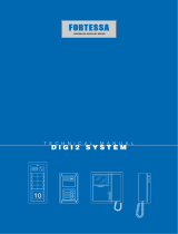
STRUCTURE
The calling module with directory consists of the following parts:
1 Two-module Kombi front.
2 Alphanumeric display, two-rows, 16-characters, back-lit.
3 Yellow back-lit name selection buttons.
4 Green back-lit number pad buttons with yellow back-lit function
buttons: “Cancel”, “Key” and “Call”.
5 Extractable connection terminal boards (MP2, MV1, MS1).
6 Additional alphanumeric keyboard (1038/72) connector.
7 Calling module microphone volume adjustment trimmer.
8 PC wire connector (CNS).
9 LCD display contrast adjustment trimmer.
10 Programming button (for use only when password is not known).
11 Calling module speaker volume adjustment trimmer.
12 Programming alphanumeric keyboard (1032/65) connector
(CNP).
13 Extractable connection terminal board (MP1).
KOMBI CALLING MODULE WITH REPERTORY Ref. 1072/12
PERFORMANCE - STRUCTURE
KOMBI CALLING MODULE WITH REPERTORY Ref. 1072/12
5
123
46
789
0
5
123
46
789
0
L2
L1
GND
PA
SP
H
P
GND
+EP
DT
MP2
MS1
MV1
SN R R1
Sch./Ref.
S/N
Data
1072/12
+
PROG.
+
CONTR.
˜
0
˜
12
+T
GND
SE1
SE2
MP1
CNA
CNP
CNS
5
13
12
11
10
9
8
7
6
4
1
2
3

4
−−−−
sec.2c
KOMBI CALL MODULE
II ED
.
V
O
P
BIBUS 2
nd
Ed. VOP - Technical Manual
DESCRIPTION OF TERMINALS AND
CONNECTORS
MP1 terminal board
~0 Power12Vac
~12 Power12Vac
+T Back-up power positive
GND Back-up power negative
SE1 Electrical lock connection (positive pole)
SE2 Electrical lock connection (negative pole)
MP2 terminal board
L1 Bus line 1st wire
L2 Bus line 2nd wire
GND Reference electrical ground
PA Hall door opener button input
SP Open door sensor contact input
MV1 terminal board
SN Video power unit on signal for video door phone systems
R Video switching enable signal for video door phone systems
R1 Video power ground
MS1 terminal board
H Door opener code time band contact input
P Mail key input
GND Reference electrical ground
+EP Auxiliary device power
DT Not used
CNA Alphabetic keyboard connector 1038/72
CNP Programming keyboard connector 1032/65
CNS PC serial line connector
The module is programmed by default with a jumper between ground
and the “SP” signal to simulate the door closed contact. Remove the
jumper and connect the sensor between GND and SP when the open
door contact is required.
Connect the electrical lock positive to terminal SE1 and the negative to
terminal SE2 when polarised electrical locks are used.
IMPORTANT: Observe the instructions contained in section 1 for
wiring and maximum distances.
TECHNICAL SPECIFICATIONS
Power: 12Vac nominal
Stand-by consumption: 300mAac max.
Maximum consumption: 600mAac max. (*)
R signal: Imax=80mA
Lock hold current: 190mA max.
Working temperature range: -10 +50°C
Humidity: 90% RH at 30°C
(*) with alphabetic keyboard 1038/72
OPERATION
CALLS TO USERS
A user can be called by entering the respective code on the keypad.
Obviously, the code must be known to do so.
The name can be sought in the integrated electronic directory if the
code is not known.
CALLS TO USERS BY SELECTING THE NAME
The following message will appear on the display:
Press
and to scroll the names and the codes. Hold either button
pressed to increase scrolling speed.
Select the name and press to call the selected user.
The apartment door phone will ring for approximately 3 seconds. Hold
pressed to send up to three consecutive calls.
Name/code display example:
The following prompt will appear on the display if
is not pressed for
longer than two seconds after selecting a name:
At this point, either press
to call or press or to scroll the name
list.
The following will appear on the display when the button is pressed:
Press
to interrupt the call to the previously selected user.
The following message will appear on the display if the user lifts the
handset:
Press
to end the conversation with the user.
The following message will appear if the user does not answer within
the programmed pick-up time:
KOMBI CALLING MODULE WITH REPERTORY Ref. 1072/12
DESCRIPTION OF TERMINALS AND CONNECTORS - TECHNICAL SPECIFICATIONS - OPERATION
KOMBI CALLING MODULE WITH REPERTORY Ref. 1072/12
Select NAME
with
↑ or ↓
To call
press
URMET DOMUS
1001
CALL
IN COURSE
TALK
PLEASE
User
does not reply

sec.2c
−−−−
5
KOMBI CALL MODULE
II ED
.
V
O
P
BIBUS 2
nd
Ed. VOP - Technical Manual
CALLS TO USERS BY SELECTING THE CODE
Dial the code of the user to be called (numeric or alphanumeric with
optional keyboard). The following will appear on the display:
Enter the code, hang up the handset and press the
to call the
selected user.
The apartment door phone will ring for approximately 3 seconds. Hold
pressed to send up to three consecutive calls.
Press
to interrupt the call to the previously selected user.
The following message will appear on the display if the user picks up
the handset:
Press
to end the conversation with the user.
The following message will appear if the user does not answer within
the programmed pick-up time:
DIRECT CALL TO CONCIERGE SWITCHBOARD
Press on a calling module installed in a system with concierge
switchboard to call it directly. This is only possible when the concierge
switchboard is in day mode, i.e. when the concierge service is operative
and the function has been activated (see “Programming”).
The following message will appear on the display:
The following will appear on the display if
is pressed and either
the concierge switchboard is in night mode or the function has not be
activated (see “Programming”).
DOOR OPENER CODES
Press the button before entering each door opener code.
Symbol “∗” will appear on the display when entering the code for each
button.
The module will open the door if the code is valid. A warning will be
output if the code is not valid.
The sequence is the same for “Generic” and “Personal” door opener
codes: press
followed by the door opener code. The following will
appear on the display:
The lock will be operated and the following message will appear if the
code is correct:
GENERIC DOOR OPENER CODES
The generic door opener codes can be used by residents and other
authorised persons to release the lock.
The calling module is dimensioned to contain up to eight generic
door opener codes for operating the electrical lock. The codes have
four digits (no letter permitted).
The eight generic door opener codes must be validated according
to the time of day. The codes will operate the door lock only if the
contact of the clock external to the module is open. Otherwise, the
eight generic codes cannot be used to open the lock.
PERSONAL DOOR OPENER CODES
A door opener code can be associated to each name. Other 250 door
opener codes can be thus programmed in addition to the generic codes.
These 250 door opener codes are not concerned by the clock contact.
BUSY FUNCTION
This function is only required in systems with more than one calling
device. This function is used to ensure that a conversation lasts
suffi ciently long following a call. The following message indicates busy
status:
The keyboard is disabled during this time.
Two cases can occur:
BUSY TIME BEFORE THE CALL USER GOES ON-HOOK
This is the maximum time for the user to pick up the handset or open
the door without loosing the call after the ring.
BUSY TIME AFTER USER GOES ON-HOOK
This is the minimum guaranteed conversation time from when the
handset is picked up.
KOMBI CALLING MODULE WITH REPERTORY Ref. 1072/12
OPERATION
Ref. 1072/12
CALL TO:
n° 1001
CALL
IN COURSE
TALK
PLEASE
User
does not reply
Select NAME
with
↑ or ↓
CALL TO:
Switchboard
CODE NOT
VALID
LOCK REL. CODE
****
Go in
Please
LINE BUSY
Please wait
KOMBI CALLING MODULE WITH REPERTORY

6
−−−−
sec.2c
KOMBI CALL MODULE
II ED
.
V
O
P
BIBUS 2
nd
Ed. VOP - Technical Manual
The main menu will appear on the display when programming mode is
accessed:
(2nd edition
only)
Use and buttons to scroll the menus. Select the required menu
and press
to confi rm.
Note:
The module will check for other devices programmed with the
same number (ID) in the system when accessing programming
mode and during programming. The following error message will
appear if other modules with the same ID are fi tted (which will
certainly be the case of a system with more than one call station):
PROGRAMMING
The module can be programmed in three ways when the system is
powered:
1 via external keyboard ref. 1032/65 (recommended method);
2 via local numeric keypad without opening the frame. The
programming password is required for this operation;
3 via PC connection.
Repetitive beeps and a message on the display in programming will
signal that other modules with the same ID are present. Change the
station number (ID) in this case.
PROGRAMMING VIA 1032/65 KEYBOARD
Programming mode is entered automatically by connecting the external
keyboard to the calling module.
Programming mode is quitted by disconnecting the external keyboard
in any menu. All previously entered data will remain valid.
See “PROGRAMMING PARAMETERS”.
PROGRAMMING VIA LOCAL KEYPAD
Programming mode can be accessed in two ways.
• The confi guration access password is known (the default
password is “9999”): enter “00” followed by the 4-digit password and
press .
The following message will appear if the password is wrong:
Password entry will be jammed for a time which increases with the
number of failed attempts after the third attempt.
• The password is not known: open the Kombi frame and press the
red button on the back.
The red programming button on the back of the unit can be pressed
in any programming menu. The data entered to this time will be
valid. Press
for three seconds to go back to the previous menu.
Press for three seconds in the main menu to quit programming.
Normal operation is automatically restored if no buttons are pressed
for over three minutes.
PROGRAMMING PARAMETERS
Refer to the local keypad programming method for programming menu
operative descriptions.
The following table shows the operative differences for programming
via 1032/65 keyboard.
KOMBI CALLING MODULE WITH REPERTORY Ref. 1072/12
PROGRAMMING
Ref. 1072/12
Main Menu
BUSY TIME
↓↑
Main Menu
Type of code
↓↑
Main Menu
Lock rel. codes
↓↑
Main Menu
Door op. time
↓↑
Main Menu
Codes/names
↓↑
Main Menu
Switchb. call
↑
Main Menu
Mod. password
↓↑
Main Menu
Association
↓↑
EXISTING
CALL MODULE N°.
Main Menu
Edition
↓
Main Menu
Cal Module n
o
↓↑
Main Menu
C. Module Type
↓↑
Main Menu
Language
↓↑
INCORRECT
PASSWORD
KOMBI CALLING MODULE WITH REPERTORY
Function Programming Programming
via local keypad
via external keyboard
Select menu Buttons and Buttons ← and →
OK (enter) Button
Button ↵
Escape
Button
(one menu up)
pressed for 3s
Button
White space Separate characters Button SP
Backspace (for correction) Separate characters Button BS
Select special characters Separate characters Button /
Delete booking of
code to be associated Button
Button BS

sec.2c
−−−−
7
KOMBI CALL MODULE
II ED
.
V
O
P
BIBUS 2
nd
Ed. VOP - Technical Manual
BUSY TIME
The busy time is split into two sub-menus.
The following message will appear on the display:
Use
and buttons to select the submenu and
button to confi rm.
PICK-UP TIME
The pick-up time is the maximum time from start of a call for the user
to answer the door phone. All other calling stations will be engaged
during this time.
All devices in the system must have the pick-up time.
The following message will appear on the display:
Use
and buttons to select and
button to confi rm.
The system will automatically go back to the main menu after a
confi rmation tone.
MINIMUM CONVERSATION TIME (BUSY)
When a user is called and answers the door phone, all other call
stations will be busy for the minimum programmed conversation time.
A communication that has just started cannot be interrupted.
All devices in the system must have the same minimum conversation
time (busy time).
The following message will appear on the display:
Use
and buttons to select and
button to confi rm.
The system will automatically go back to the main menu after a
confi rmation tone.
DOOR LOCK ACTIVATION TIME
The relay controlling the door lock can be managed in pulse mode
(approximately 500 ms) or stabile mode (from 1 to 30 s).
The following message will appear on the display:
Enter the number of seconds and press
to confi rm. Press
to
cancel the entry.
The system will automatically go back to the main menu after a
confi rmation tone.
EDITION
The module can be confi gured as a 1st edition or 2nd edition device.
The module must be programmed as 1st edition if there is even
only one 1st edition device in the system (when replacing parts
in old systems). The device must be programmed as 2nd edition
when all the devices in the system are 2nd edition.
The following message will appear on the display:
(2nd edition
only)
Use and buttons to select and
button to confi rm.
The system will automatically go back to the main menu after a
confi rmation tone.
LANGUAGE
The following message will appear on the display:
Use
and buttons to select and
button to confi rm.
The system will automatically go back to the main menu after a
confi rmation tone.
TYPE OF STATION
The module can be confi gured as a main station or as a secondary
station. A secondary module can be used to send calls to internal
stations in the riser but cannot be used to call the switchboard. This
programming step will not appear in 1st edition systems.
The following message will appear on the display:
Use
and buttons to select and
button to confi rm.
The system will automatically go back to the main menu after a
confi rmation tone.
STATION NUMBER (ID)
A number from 1 to 12 is assigned to each main calling station.
A number from 0 to 9 is assigned to each secondary station. The
secondary number is in the range from A to J in systems with
alphabetic prefi x.
A to J programmed on a secondary station will automatically be
reprogrammed as a prefi x code format. ID from 0 to 9 on a secondary
station will automatically be reprogrammed as a numeric code format.
The following message will appear on the display:
Enter the station number and press
to confi rm. Press to cancel
the entry.
The system will automatically go back to the main menu after a
confi rmation tone.
1st edition systems: the station number must be in the range from 1
to 12 (there are not secondary stations in the system). Assign 15 as
station number to use the clone function.
KOMBI CALLING MODULE WITH REPERTORY Ref. 1072/12
PROGRAMMING
== BUSY TIME ==
PICK-UP TIME
↓
== BUSY TIME ==
BUSY TIME
↑
PICK-UP TIME: 20s
<10><20><30><40>
BUSY TIME: 20s
<10><20><30><40>
= Door op. time =
0 seconds
Ref. 1072/12
Edition: II edition
<I ED> <II ED>
== Language ==
Italiano
↓
C. MOD. TYPE:
<MA.> <SEC>
= Station n° =
Station: 1
KOMBI CALLING MODULE WITH REPERTORY

8
−−−−
sec.2c
KOMBI CALL MODULE
II ED
.
V
O
P
BIBUS 2
nd
Ed. VOP - Technical Manual
DOOR OPENER CODES
The eight generic door opener codes can be stored in sequence.
The following message will appear on the display:
Enter the 4-digit code and press
to confi rm. Press to cancel the
entry. The system automatically prepares to enter the second code
after a confi rmation tone.
The system will automatically return to the main menu at the end of
programming. Alternatively, press for three seconds to go back to
the main menu.
CODE TYPE
The module can be used to call users with numeric codes
(0001-9999), alphanumeric codes with alphabetic prefi x (x000-x999)
and alphanumeric codes with alphabetic suffi x (000x-999x). Letters
from A to J can be used.
The following message will appear on the display:
Use
and
buttons to select the Code Type and
button to confi rm.
CODES/NAMES
The names and respective codes can be programmed in this menu.
The following message will appear on the display:
Use
and
buttons to select the submenu and
button to confi rm.
ENTER DATA
The user codes and respective names and personal door opener
codes can be programmed in this sub-menu.
The fi rst free position in the 250 item table will appear (one item for
each user):
Enter the numeric or alphanumeric code formed by a variable number
of digits from 1 to 4 and press to confi rm. Press to correct.
Press for longer than three seconds to go back to the previous
menu.
The same code can be entered in two or three positions in an
apartment where two or three door phones are connected in parallel
(you are advised to use adjacent positions to simplify the association).
The following will appear on the display after entering the code:
The name can be entered at a later time. In this case, press
to enter
the new code. Proceed as follows if the user name is known. Press
and on the calling module keypad to seek the required character.
The cursor will shift right by one position to enter a new character after
approximately one second if no other button is pressed. Press
to
delete the last entered character. Use programming keyboard 1032/65
to considerably facilitate entry of names.
The same name can be assigned to different codes.
Enter the name and press
to enter the respective door opener
code.
The following message will appear on the display:
Enter the personal door opener code and press
to confi rm. The
general code programmed during the “Door opener code” phase
cannot be entered. Press without entering a code to skip assigning
a door opener code to the user.
EDIT DATA
The data related to the entered users can be edited in this sub-menu.
The following search criteria can be applied:
• search by position in table (1-250);
• search by name.
The following message will appear on the display:
Use the arrows to select the search criteria and press
to confi rm.
SEARCH BY POSITION
This sub-menu can be used either to edit the user code, name or door
opener code in a certain position in the table or to delete the record.
The following message will appear on the display:
Use the arrows to select the position and press
to confi rm.
At this point, you can:
• Delete the record by pressing (or bs button on keyboard 1032/65
to delete the code); a confi rmation window will appear before the
record is deleted from the table.
• Change the user code: enter a new code and press to confi rm
then change the name.
KOMBI CALLING MODULE WITH REPERTORY Ref. 1072/12
PROGRAMMING
Ref. 1072/12
Lock rel. codes
1° Code:
= Code Type =
Num. 1.9999
↓
= Code Type =
Suff. 000x.999x ↑
= Code Type =
Pref. x000.x999
↓↑
= Code/Name =
Enter data
↓
= Code/Name =
Clear all
↑
= Code/Name =
Modify data
↓↑
Position: 1
Code:
Code 1001 Name:
Code Lock rel.
Modify data
Search by pos.
↓
Modify data
Search by name
↑
Position: 1
Code: 1001
KOMBI CALLING MODULE WITH REPERTORY

sec.2c
−−−−
9
KOMBI CALL MODULE
II ED
.
V
O
P
BIBUS 2
nd
Ed. VOP - Technical Manual
• Change the name: after changing the user code, a form similar to
the name enter form will appear. Edit the name and press to
confi rm.
• Change the user door opener code: a form similar to that for entering
door opener codes will appear after editing the name. Edit the code
and press to confi rm the operation.
SEARCH BY NAME
This sub-menu can be used to edit a name or door opener code
associated to a record.
The following message will appear on the display:
Use the arrows to select the name and press
to confi rm.
At this point, you can:
• Change the name: edit the name and press
to confi rm.
• Change the user door opener code: a form similar to that for entering
door opener codes will appear after editing the name. Edit the code
and press to confi rm the operation.
CLEAR ALL
This sub-menu can be used to clear the name table with respective
user codes and personal door opener code.
The following message will appear on the display:
Use the arrows to select the answer and press
to confi rm.
ASSOCIATION PROCEDURE
The door phone programming procedure consists of two steps:
A. Door phone booking procedure (to be made on a calling station)
B. Door phone programming procedure (to be made in the
apartments).
A: Door phone booking procedure
Select the Association menu. The following message will appear on
the display:
1 Scroll the record list with the scroll arrows.
Press
to confi rm the records to be added to the booking list
(a
symbol will appear next to the position). To delete a record
from the booking list, press
instead of (the
symbol will
disappear).
2 The door phones can be programmed in the same order after
creating the booking list. Press
. The following will appear on the
display:
Proceed by programming the door phones.
B: Door phone programming procedure
1 Go to the fi rst booked user, hold the button pressed and lift the
door phone handset. Two confi rmation beeps will be heard and the
LED will fl ash to indicate that it has been programmed.
2 Go to the other booked users and repeat the operations.
Refer to the supplied sheet to remember the code/button association
sequence.
The entire operation (booking and programming) must be
repeated for each module in the system in 1st edition systems,
unless the “Clone” function (see below) is used. The door phone
programming procedure does not need to be repeated on all
calling systems in 2nd edition systems.
The module will quit programming mode for the following events:
• end of door phone programming
• 10 minute time-out after the last operation
• pressing the red programming button
• pressing any module key and entering the programming password.
How to associate 2/3 door phones in parallel in 2nd edition systems
To install two or three door phones in the same apartment and make
them all ring when called, press the
button corresponding to the
user with parallel door phones twice or three times during the door
phone booking procedure.
When you reach the apartment where the parallel door phones
are installed according to the programming sequence, repeat the
programming sequence on both door phones.
How to associate 2 door phones in parallel in 2nd edition systems
To install two door phones in one apartment and make them both ring
when a call is received, press
corresponding to the user twice with
the door phones in parallel when booking the door phones.
When you reach the apartment where the parallel door phones
are installed according to the programming sequence, repeat the
programming sequence on both door phones.
Using the “clone” function in 1st edition systems
A single association between calling station codes and respective door
phones can be made in systems without switchboard and without door
open signal function.
The remaining call stations can be clones of the fi rst station (the
master station) and copy the codes associated to the single users.
To enable this function:
• defi ne the master station as address “1” (where to make the
association).
• defi ne all other stations as address “15”.
Obviously, all names, user codes and door opener codes must be
programmed in “clone” stations.
EDIT PASSWORD
This menu can be used to edit the password for accessing module
programming.
The following message will appear on the display:
Enter the new 4-digit password and press
to confi rm.
KOMBI CALLING MODULE WITH REPERTORY Ref. 1072/12
PROGRAMMING
Ref. 1072/12
John Doe
Code: 1001
Are you sure?
<YES> <NO>
Position: 1
C:1001 Associate?
MODULE BEING
PROGRAMMED
SEQUENZA DI ASSOCIAZIONE
ASSOCIATION SEQUENCE
N° DELLA POSTAZIONE (ID):
CALL MODULE NUMBER (ID):
SEQ. NOMINATIVO PULSANTE / CODICE PIANO VARIE
USER NAME PUSHBUTTON / CODE FLOOR VARIOUS
1
2
3
4
5
KOMBI CALLING MODULE WITH REPERTORY
Password: 9999
New:

10
−−−−
sec.2c
KOMBI CALL MODULE
II ED
.
V
O
P
BIBUS 2
nd
Ed. VOP - Technical Manual
2) Download data to PC: (refer to the B-BUS 2nd edition program for
additional information). The following will appear on the module.
The module will become operative again at the end of the operation.
ADDITIONAL INFORMATION
The following message will appear if the “Bus” is down:
A door opener code can be entered in this situation.
The fi rmware version and the revision date will appear for approximately
one second when the display is switched on, e.g.:
VOLUME ADJUSTMENT
Volumes are calibrated by default so not to require adjustments in
most cases.
Use a screwdriver to adjust the trimmers if required.
DISPLAY CONTRAST REGULATION
The display contrast is set at the factory and will not need to be
adjusted in most installations.
Use a screwdriver to adjust the trimmers if required.
ADDITIONAL ALPHABETIC KEYBOARD Ref. 1038/72
The additional alphabetic keyboard Ref. 1038/72 can be used to enter
letters for dialling call codes.
The device must be combined with a calling module Ref. 1072/12 to
which it is connected by means of the specifi c connection wire. In any
case, the device must be arranged UNDERNEATH (or by THE SIDE
OF) the calling module.
E
ABC
DF
GH I
J
SWITCHBOARD CALL ENABLE
This menu is used to enable direct concierge switchboard calls simply
by pressing . The function is only active when the door phone is in
day mode.
The following message will appear on the display:
Use the arrows to select and press to confi rm.
DEFAULT SETTINGS
The default settings of the device are:
System type: 2nd edition
Station type: main
Code format: numeric (0001–9999)
Station number: 1
Pick-up time: 20s
Busy time: 20s
Door opener time: pulse
To restore default settings:
• Disconnect module power.
• Hold the red programming button pressed and power up the
module.
• Hold the button pressed for approximately 10 seconds and wait for
a tone.
• Release the button.
PROGRAMMING VIA PC
The calling module can be programmed and confi gured rapidly by
means of a PC connected to the serial port (8) of the calling module by
means of a special wire Ref. 1072/57 (optional, not provided with the
product).
The B-BUS 2nd edition PC program can be used for simple and fast
module programming.
The B-BUS 2nd edition program can be downloaded free of charge
from the Urmet Domus web site (http://www.urmetdomus.com).
Minimum PC requirements are:
• 486 processor or above
• Windows 95 or 98 operating system
• Use of a mouse is recommended.
The signals on the 9-pin female D-sub connector are:
Pin 1 n.c.
Pin 2 PC data RX
Pin 3 PC data TX
Pin 4 n.c.
Pin 5 Ground
Pin 6 n.c.
Pin 7 n.c.
Pin 8 n.c.
Pin 9 n.c.
Connect wire 1072/57 between module and PC serial port to carry out
the following operations:
1) Upload data from PC (refer to the B-BUS 2nd edition program for
additional information). The following will appear on the module.
The module will become operative again at the end of the
operation.
KOMBI CALLING MODULE WITH REPERTORY Ref. 1072/12
ADDITIONAL INFORMATION - VOLUME ADJUSTMENT - DISPLAY CONTRAST REGULATION -
ADDITIONAL ALPHABETIC KEYBOARD Ref. 1038/72
NO CONNECTION
Bibus System
V1.0 10/10/01
Ref. 1072/12
Call button
<YES> <NO>
Data reception
in course…
PLEASE WAIT
KOMBI CALLING MODULE WITH REPERTORY

sec.2c
−−−−
11
KOMBI CALL MODULE
II ED
.
V
O
P
BIBUS 2
nd
Ed. VOP - Technical Manual
WALL-MOUNTED VERSION WITH CASE AND HOOD
The case and hood is provided with frame and module holder. The
available models and the dimensions are shown in Technical product
manual - door phone and video door phone systems section “Panels
Kombi”.
Fasten the hood to the wall by means of three bolts.
Arrange the hole for passing the wires through the lower area of the
casing and the head.
Fasten the lower head of the module holder after fi tting the frame
between the casing and the head.
Close the plate and fasten the upper head to the casing.
ACCESSORY INSTALLATION
FLUSH-MOUNTED VERSION WITH WALL COVER
FRAME
The wall cover frames are used to conceal possible irregularity of the
wall surrounding the fl ush-mounting box. The available models and the
dimensions are shown in Technical product manual - door phone and
video door phone systems section “Panels Kombi”.
Embed the fl ush-mounting box in the wall, position the wall cover
frame and fasten the module holder lower head.
FLUSH-MOUNTED VERSION WITH RAIN HOOD
Rain hoods are used to protect the calling module from the weather.
The available models and the dimensions are shown in Technical
product manual - door phone and video door phone systems section
“Panels Kombi”.
Embed the fl ush-mounting box in the wall, position the rain hood and
fasten it by means of the module holder lower head.
INSTALLATION
The calling module Ref. 1072/12 with repertory can be used alone
or in combination with camera unit and/or alphabet keyboard add-on
Ref. 1038/72.
Examples of modular constructions using 2, 3 or 4 module holder
frames with respective fl ush-mounting boxes are shown below.
The door unit module should be installed at a height of approximately
1.55 - 1.60 metres.
Important
The module should not be illuminated from behind to make the calling
module display easier to read. Never direct the module towards strong
sources of light (e.g. the sun, lampposts, light bulbs, fl ashes or glare).
FLUSH-MOUNTED VERSION
Fit the fl ush-mounting box in line with the wall: it must not project.
Fasten the screws in the specifi cally provided holes to bring the head
in line with the wall if the box is too deeply embedded. This will prevent
distorting the lower module holder frame head (Fig. 1).
Fasten the calling module by fastening the lower head fi rst (Fig. 2) and
upper head later (Fig. 3) after installing the fl ush-mounting box.
The following versions of frame holders and fl ush-mounting boxes are
available:
• 2 modules H=204 Ref. 825/22
• 3 modules H=294 Ref. 825/23
• 4 modules H=384 Ref. 825/24
KOMBI CALLING MODULE WITH REPERTORY Ref. 1072/12
INSTALLATION - ACCESSORY INSTALLATION
h = 1,55 ÷ 1,60 m
5
123
46
789
0
118 mm45 mm
H
Fig. 1
Fig. 2
L2
L1
GND
PA
SP
H
P
GND
+EP
DT
MP2
MS1
MV1
SN R R1
Sch./Ref.
S/N
Data
1072/12
+
PROG.
+
CONTR.
˜
0
˜
12
+T
GND
SE1
SE2
MP1
CNA
CNP
CNS
Fig. 3
5
123
46
789
0
L2
L1
GND
PA
SP
H
P
GND
+EP
DT
MP2
MS1
MV1
SN R R1
Sch./Ref.
S/N
Data
1072/12
+
PROG.
+
CONTR.
˜
0
˜
12
+T
GND
SE1
SE2
MP1
CNA
CNP
CNS
Ref. 1072/12KOMBI CALLING MODULE WITH REPERTORY
5
123
46
789
0

12
−−−−
sec.2c
KOMBI CALL MODULE
II ED
.
V
O
P
BIBUS 2
nd
Ed. VOP - Technical Manual
Fasten the lower side of the fl ush-mounting box using the two screws
provided for this purpose so that the head projects from the wall by
approximately 2 mm to prevent distortion and compensate for the
difference in level with the lower resting edge of the rain hood.
Then fasten the upper head of the module holder to the fl ush-mounting
box to fi nish fastening the hood.
EXAMPLES OF MODULAR CONSTRUCTIONS
Recommended calling module constructions are shown below.
KOMBI CALLING MODULE WITH REPERTORY Ref. 1072/12
ACCESSORY INSTALLATION
5
123
46
789
0
1,55 - 1,60 m
Ref. 825/24Ref. 825/23
E
ABC
DF
GH I
J
Ref.
1072/12
Ref.
1072/12
Ref.
1072/12
Ref.
825/70
Ref.
1038/72
Ref.
1038/72
Ref.
1072/12
Ref.
825/70
Ref.
1038/72
Ref.
1072/12
Ref.
1038/72
E
ABC
DF
GH I
J
Ref. 825/22
Ref.
1072/12
2 modules 3 modules 4 modules
5
123
46
789
0
5
123
46
789
0
5
123
46
789
0
L2
L1
GND
PA
SP
H
P
GND
+EP
DT
MP2
MS1
MV1
SN R R1
Sch./Ref.
S/N
Data
1072/12
+
PROG.
+
CONTR.
˜
0
˜
12
+T
GND
SE1
SE2
MP1
CNA
CNP
CNS
L2
L1
GND
PA
SP
H
P
GND
+EP
DT
MP2
MS1
MV1
SN R R1
Sch./Ref.
S/N
Data
1072/12
+
PROG.
+
CONTR.
˜
0
˜
12
+T
GND
SE1
SE2
MP1
CNA
CNP
CNS
L2
L1
GND
PA
SP
H
P
GND
+EP
DT
MP2
MS1
MV1
SN R R1
Sch./Ref.
S/N
Data
1072/12
+
PROG.
+
CONTR.
˜
0
˜
12
+T
GND
SE1
SE2
MP1
CNA
CNP
CNS
Ref. 1072/12KOMBI CALLING MODULE WITH REPERTORY
/