Page is loading ...

sec.3e
−−−−
1
BIBUS 2
nd
Ed. VOP - Technical Manual
SINTHESI SLIM PANEL
WITH DOOR UNIT
AND DIGITISER
SECTION 3E
Download from
www.urmet.com
Technical Manuals area

CONTENTS BIBUS II^ Ed. VOP SYSTEM - Section 3E
SECTION 3E CONTENTS
BIBUS II^ Ed. VOP SYSTEM
I
−−−−
sec.3e
BIBUS 2
nd
Ed. VOP - Technical Manual
Sec. Pag.
SINTHESI SLIM PANEL WITH DOOR UNIT AND DIGITISER
LOUDSPEAKING UNIT WITH INTEGRATED DIGITALIZER - SINTHESI SLIM REF. 1072/6
PERFORMANCE ..................................................................................................................................................................................3e ................3
STRUCTURE .......................................................................................................................................................................................3e ................3
DESCRIPTION OF TERMINAL BOARDS ............................................................................................................................................3e ................3
TECHNICAL SPECIFICATIONS ..........................................................................................................................................................3e ................3
CONNECTIONS ...................................................................................................................................................................................3e ................3
FUNCTION ...........................................................................................................................................................................................3e ................3
Calls ..................................................................................................................................................................................................3e ................3
Staircase lights function ....................................................................................................................................................................3e ................4
Busy function ....................................................................................................................................................................................3e ................4
PROGRAMMING ..................................................................................................................................................................................3e ................4
Default programming ........................................................................................................................................................................3e ................4
Simpliedprogramming ....................................................................................................................................................................3e ................4
Complete programming with external device....................................................................................................................................3e ................5
Volume regulation .............................................................................................................................................................................3e ................7
Troubleshooting ................................................................................................................................................................................3e ................7
PROGRAMMING SUMMARY DIAGRAMS ..........................................................................................................................................3e ................8
SINTHESI SLIM PANEL
BUTTON MODULES ............................................................................................................................................................................3e ..............11
Name tag replacement .....................................................................................................................................................................3e ..............11
Repertory modules Ref. 1141/50 ......................................................................................................................................................3e ..............12
Camera module Ref. 1741/30...........................................................................................................................................................3e ..............12
INSTALLATION ....................................................................................................................................................................................3e ..............13
Wall fastening ...................................................................................................................................................................................3e ..............13
Box union ..........................................................................................................................................................................................3e ..............13
Module installation ............................................................................................................................................................................3e ..............14
Basic circuit vertical installation ........................................................................................................................................................3e ..............15
Basic circuit horizontal installation ....................................................................................................................................................3e ..............16
Frame and module assembly ...........................................................................................................................................................3e ..............17
Removing modules from module holder frame .................................................................................................................................3e ..............18
Frame assembly ...............................................................................................................................................................................3e ..............19
DIMENSIONS .......................................................................................................................................................................................3e ..............20
DOOR PHONE SYSTEM - Example of modular constructions with various capacities .......................................................................3e ..............21
VIDEO DOOR PHONE SYSTEMS - Example of modular constructions with various capacities ........................................................3e ..............24

sec.3e
−−−−
3
SINTHESI SLIM PANEL WITH DOOR UNIT AND DIGITISER
BIBUS 2
nd
Ed. VOP - Technical Manual
LOUDSPEAKING UNIT WITH INTEGRATED DIGITALIZER
SINTHESI SLIM Ref. 1072/6
PERFORMANCE - STRUCTURE - DESCRIPTION OF TERMINAL BOARDS
TECHNICAL SPECIFICATIONS - CONNECTIONS - FUNCTION
LOUDSPEAKING UNIT - SINTHESI SLIM Ref. 1072/6
ON
1 2
1
2
4
5
3
FRONT SIDE
J3
BASIC CIRCUIT
J1
J2
TOP
6
MTT1
7
MTT2
LOUDSPEAKING UNIT WITH INTEGRATED
DIGITALIZER - SINTHESI SLIM Ref. 1072/6
PERFORMANCE
• CanbettedinSinthesiSlim1141panels.
• Maximum 40 user buttons in each door unit.
• Possibility of assigning alphanumeric call button code with letter
prexorsufxA-J.
• The digitiser is programmed by means of an external programming
device Ref. 1072/60 which in turn must be connected to a push-
button panel Ref. 1032/65.
• Simplied programming with LED button and two dip-switches in
simple systems.
• Possibility of programming one or more buttons for controlling a
special decoder (“staircase lights” function).
• Electrical relay load control actuator with NC-C-NO outputs and
programmable activation time, from 1 to 30s.
• Programmable door phone hang-up waiting time (10, 20, 30, 40s).
• Programmable minimum guaranteed conversation time (10, 20, 30,
40s).
• Maximum conversation time: 250s.
• Open door contact input.
• Hall button timed input.
• Acoustic call sent signal.
• Busy function signalled by busy tone when a button is pressed to
busy time-out.
• Two trimmers for adjusting speaker and microphone volume.
• Opto-isolated control signal management for video door phone
systems.
• Possibility of programming a pre-set button for direct switchboard
calls (day state only).
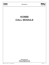
STRUCTURE
The digitiser consists of the following parts:
Front side
1) Microphone volume adjustment trimmer.
2) Speaker volume adjustment trimmer.
3) SimpliedprogrammingLEDbutton.
4) Programming connector for adapter Ref. 1072/60 and keyboard
Ref. 1032/65.
5) Simpliedprogrammingdip-switch.
Basic circuit
6) Terminal board for system connection.
7) Connector for button modules Ref. 1072/31... Ref. 1072/34.
DESCRIPTION OF TERMINAL BOARDS
Terminal board MTT1
R1 Video power earth
R Video switching enable signal for video systems
L1 Bus Line 1st connector
L2 Bus Line 2nd connector
GND Reference earth PA, SP
Terminal board MTT2
SP Open door sensor contact input (closed with closed door)
PA Hall door opener button input (normally open)
~0 Relay power for electrical lock
~12 Relay power for electrical lock
C Relay exchange electrical lock common contact
NC Electrical lock relay normally closed contact
NO Electrical lock relay normally open contact
TECHNICAL SPECIFICATIONS
Stand-by consumption: 6.5mA max.
Active voice consumption: 40mA max.
Relay contact: 30V 2A
R signal: Imax=80mA
Working temperature range: -10 +50°C
Humidity: 90% RH @ 30°C
CONNECTIONS
IMPORTANT: Observe the instructions contained in section 1 for
wiring and maximum distances.
Up to 40 user buttons can be connected to the door unit. The door
unit is programmed by default with a jumper between the earth and the
“SP” signal to simulate the door closed contact. Remove the jumper
and connect the sensor between GND and SP when the open door
contact is required.
NOTE: internal calling station circuits are power by bus voltage.
FUNCTION
CALLS
Up to 40 users can be called by pressing the corresponding buttons
on the panels associated to the door unit with digitiser Ref. 1072/6.
Additionally, a concierge switchboard Ref. 1072/41 can be called,
simply by pressing a call button associated to code 0000 during
programming (day mode only). A courtesy ring, similar to that generated
on a called door phone, will be heard.

4
−−−−
sec.3e
SINTHESI SLIM PANEL WITH DOOR UNIT AND DIGITISER
BIBUS 2
nd
Ed. VOP - Technical Manual
LOUDSPEAKING UNIT WITH INTEGRATED DIGITALIZER
SINTHESI SLIM Ref. 1072/6
PROGRAMMING
Ref. 1072/6LOUDSPEAKING UNIT - SINTHESI SLIM
ON
1 21 2
ON
1 2
ON
1 2
ON
1 2
ON
Dip-switch position
Main station number
Not defined (for programming with
an external keyboard)
Station 1
Station 2
Station 3
SEQUENZA DI ASSOCIAZIONE
ASSOCIATION SEQUENCE
N° DELLA POSTAZIONE (ID):
CALL MODULE NUMBER (ID):
SEQ. NOMINATIVO PULSANTE / CODICE PIANO VARIE
USER NAME PUSHBUTTON / CODE FLOOR VARIOUS
1
2
3
4
5
STAIRCASE LIGHTS FUNCTION
Press the button programmed for this function. A command will be sent
tothespecialdecoderandaconrmationbeepwillbeheard.
NOTE: if the staircase lights button is pressed during the programming
procedure, it will be reprogrammed with the user code
corresponding to the position.
BUSY FUNCTION
This function is only required in systems with more than one calling
device. This function is used to ensure that a conversation lasts
sufcientlylongfollowingacall.Anintermittentbeepwillbeheardon
the speaker for the time before the busy time-out and the panel will be
disabled.
Two cases can occur:
BUSY TIME BEFORE THE CALL USER GOES ON-HOOK:
This is the maximum time for the user to lift the handset or open the
door without loosing the call after the ring.
BUSY TIME AFTER USER GOES ON-HOOK
This is the minimum guaranteed conversation time from when the
handset is lifted.
PROGRAMMING
The door unit can be programmed in systems with up to three main
calling stations without secondary stations simply by means of the
LED button and the two dip switches without using external devices.
In complex systems and for special programming needs, the device
can be programmed with adapter Ref. 1072/60 to be inserted in the
specicdedicatedminidinconnector.Theprogrammingadaptermust
be connected to the programming keyboard Ref. 1032/65.
The system must be powered for programming.
DEFAULT PROGRAMMING
The device default settings are:
System type: 2nd edition
Station type: main
Code format: numeric (0001–9999)
Station number: 1
Off-hook waiting time: 40s
Busy time: 20s
Door opener time: 3s
Code button association
LLLL P1
1002 P2
. .
. .
1040 P40
To restore default settings, insert the programming device and hold bs
button pressed for longer than three seconds until you hear a beep.
Alternatively, without the programming device, hold the programming
button (3) pressed for longer than three seconds until you hear a
beep.
SIMPLIFIED PROGRAMMING
The door unit and the door phones can be programmed without external
devices in 2nd edition systems consisting of main calling stations only
(up to three). The following parameters can be programmed in this
case:
• Main station number: with dip-switch (1, 2, 3).
• Lock activation time: with LED button (1-30s).
• Door phone programming with LED button (predetermined user
codes).
STATION NUMBER (ID)
The two dip-switches determine the main station number as shown in
the following table:
ELECTRICAL LOCK TIME
Press the programming button (3) and wait for the respective LED to
come on.
Beeps will be repeatedly generated if there are other stations with
the same ID. Press the button again to quit the operation, correct the
mistake with the dip-switches and repeat the operation.
Hold the “hall” button pressed for the time to be programmed (up to 30
s).Thedoorunitwillacquirethevalueandaconrmationbeepwillbe
heard. Press the programming button to return to normal operation.
DOOR PHONE PROGRAMMING
The door unit is programmed by default at the factory.
Consequently, the code-button association phase can be skipped
in systems without secondary units. In this case, go to the door
phone programming procedure directly. The procedure consists of two
steps:
A. Door phone booking (to be made on a calling station).
B. Door phone programming.
A: Door phone booking (to be made on a calling station)
Press the programming button and wait for the respective LED
to come on. Press the user buttons to be associated with the
door phones once. The booking sequence according to which the
buttons are pressed must be the same as the order in which the
operator will go to the apartments.
DO NOT press the switchboard call button.
B: Door phone programming
1. Wait for 30s until the LED starts blinking.
2. Goto the rstbooked user,hold the buttonpressed and liftthe
doorphonehandset.Twoconrmationbeepswillbeheardandthe
LEDwillashtoindicatethatithasbeenprogrammed.
3. Go to the other booked users and repeat the operations.
Refer to the attached sheet to remember the code/button association
sequence.
IMPORTANT: The LED will start blinking if the buttons are not
booked and no operation is carried out for 30 seconds during the
programming procedure. In this case, press the programming button to
quit programming. If required, press it again to resume programming.

sec.3e
−−−−
5
SINTHESI SLIM PANEL WITH DOOR UNIT AND DIGITISER
BIBUS 2
nd
Ed. VOP - Technical Manual
LOUDSPEAKING UNIT WITH INTEGRATED DIGITALIZER
SINTHESI SLIM Ref. 1072/6
PROGRAMMING
LOUDSPEAKING UNIT - SINTHESI SLIM
1 2
ON
Ref. 1072/6
ASSOCIATING 2/3 DOOR PHONES IN PARALLEL IN 2ND
EDITION SYSTEMS USING THE SIMPLIFIED PROGRAMMING
PROCEDURE
To install two or three door phones in one apartment and make them
both ring when a call is received, press the button related to the user
twice or three times with the door phones in parallel when booking the
door phones.
When you reach the apartment where the parallel door phones
are installed according to the programming sequence, repeat the
programming sequence on both door phones.
COMPLETE PROGRAMMING WITH EXTERNAL
DEVICE
Insertionoftheprogrammingdeviceisconrmedbytwobeepsandby
the led lighting.
Arrange the dip switches (5) in the position shown in the following
gurewhileprogrammingwithexternaldevice:
All data will be lost if the dip switches are moved also after ending the
programming procedure.
Parameters can be programmed or reprogrammed in any order until
the keyboard is extracted. Two beeps will be heard to conrm data
programming. A KO signal (two beeps, the second of which at a lower
frequency) will be heard if the programming is not valid.
Repetitive beeps will be heard in programming if other modules with
the same ID are present.
Press the button to silence the signal.
You are advised to program the data in the following order for the sake
of simplicity.
SYSTEM TYPE
The digitiser can be congured as 1st edition or 2nd edition. The
digitiser must be programmed as 1st edition if there is even only
one 1st edition device in the system (when replacing parts in old
systems). The device must be programmed as 2nd edition when
all the devices in the system are 2nd edition.
Letter“M”identiesthetypeofsystem:
press M1 ↵ to program 1st edition
press M2 ↵ to program 2nd edition
The device will repeatedly beep if there are other modules with the
same ID. Press the button to silence the signal.
The two dip-switches must not be in the ON position to program this
parameter successfully.
STATION TYPE
Thedigitisercanbeconguredasamainstationorasasecondary
station. A secondary digitiser can be used to send calls to internal
stations in the riser but cannot be used to call the switchboard. In
the case of 1st edition systems, the digitiser will be automatically
congured as a main station and should not be changed.
Letter“I”identiesthetypeofstation:
press I0 ↵ to program the main station
press I1 ↵ to program the secondary station
The device will repeatedly beep if there are other modules with the
same ID. Press the button to silence the signal.
The two dip-switches must not be in the ON position to program this
parameter successfully.
CODE FORMAT
The digitiser can be used to call users with numeric codes
(0001-9999),alphanumeric codeswith alphabeticprex(x000-x999)
and alphanumeric codes with alphabetic sufx (000x-999x). Letters
fromAtoJcanbeused.
Letter“F”identiesthetypeofprogrammablecode:
numeric code F1 ↵
codewithalphabeticprex: F2↵
codewithalphabeticsufx: F3↵
1st edition system: this programming is not required.
STATION NUMBER (ID)
A number from 1 to 12 is assigned to each main calling station. A
number from 0 to 9 is assigned to each secondary station.
The secondary number is in the range from A to J in systems with
alphabeticprex.
Letter“N”identiesthestationnumber:
x station number: Nx ↵
A to J programmed on a secondary station will automatically be
reprogrammedasaprexcodeformat.IDfrom0to9onasecondary
station will automatically be reprogrammed as a numeric code format.
The two dip-switches must not be in the ON position to program this
parameter successfully.
1st edition system: the station number must be in the range from 1
to 12 (there are not secondary stations in the system). Assign F as
station number to use the clone function.
OFF-HOOK WAITING TIME
The off-hook waiting time is the maximum time of a call in which the
user can answer the door phone.
All other calling stations will be engaged during this time. All devices in
the system must have the same off-hook waiting time.
Letter “G” identities the off-hook waiting time:
10s waiting time: G1 ↵
20s waiting time: G2 ↵
30s waiting time: G3 ↵
40s waiting time: G4 ↵
MINIMUM CONVERSATION TIME (BUSY)
When a user is called and answers the door phone, all other call
stations will be busy for the minimum programmed conversation time.
A communication that has just started cannot be interrupted. All
devices in the system must have the same minimum conversation time
(busy time).
Letter “O” identities the off-hook waiting time:
10s busy: O1 ↵
20s busy: O2 ↵
30s busy: O3 ↵
40s busy: O4 ↵
DOOR LOCK ACTIVATION TIME
The relay controlling the door lock can be managed in pulse mode
(approximately 600 ms) or stabile mode (from 1 to 30 s).
Letter “D” identities the lock activation time:
door lock pulse: D00 ↵
door lock xy seconds: Dxy ↵

6
−−−−
sec.3e
SINTHESI SLIM PANEL WITH DOOR UNIT AND DIGITISER
BIBUS 2
nd
Ed. VOP - Technical Manual
LOUDSPEAKING UNIT - SINTHESI SLIM
SEQUENZA DI ASSOCIAZIONE
ASSOCIATION SEQUENCE
N° DELLA POSTAZIONE (ID):
CALL MODULE NUMBER (ID):
SEQ. NOMINATIVO PULSANTE / CODICE PIANO VARIE
USER NAME PUSHBUTTON / CODE FLOOR VARIOUS
1
2
3
4
5
button 1
button 4
button 6
button 5
button 9
button 11
button 10
button 8
button 7
button 3
button 2
LOUDSPEAKING UNIT WITH INTEGRATED DIGITALIZER
SINTHESI SLIM Ref. 1072/6
PROGRAMMING
Ref. 1072/6
CODE BUTTON ASSOCIATION
This is the step in which user codes to be programmed are associated
to each button connected to the digitiser.
The call code sequence is:
Cxyzw Pnm ↵
Where xyzw is the user code and nm is the calling station button
number.
The user code xyzw can have the following values
• 0001-9999: for numeric code formats
• x000-x999: foralphabeticprexcodeformats(xfromAtoJ)
• 000x-999x: foralphabeticsufxcodeformats(xfromAtoJ)
• 0000: for direct calls to switchboard in day mode.
• LLLL: for “staircase lights” function.
The number of the nm button depends on the position of the button:
Once a code is programmed, press button ↵ to automatically program
call code xyzw+1 on button nm+1. For example, the calling sequence
C1000P01 ↵ ↵ ↵ will program code 1000 on button 01, code 1002
button 02 and code 1002 on button 03.
1st edition system: this programming is not required.
PROGRAMMING DOOR PHONES IN 2ND EDITION SYSTEMS
USING THE PROGRAMMING ADAPTER
The door phone programming sequence consists of two steps:
A. Door phone booking (to be made on a calling station).
B. Door phone programming (to be made in the apartments).
A: Door phone booking
1. InsertadapterRef.1072/60inthespecicminidinconnector.
2. Press the user buttons to be associated with the door phones
once. The booking sequence according to which the buttons are
pressed must be the same as the order in which the operator will
go to the apartments. DO NOT press the switchboard call button
or the “staircase lights” function.
3. A beep will be heard after 30 seconds from last pressing a user
button (end of booking).
4. Leave the adapter Ref. 1072/60 in the digitiser and go to the
apartments to program the doorphones.
B: Door phone programming
1. Goto the rstbooked user,hold the buttonpressed and liftthe
doorphonehandset.Twoconrmationbeepswillbeheardandthe
LEDwillashtoindicatethatithasbeenprogrammed.
2. Go to the other booked users and repeat the operations.
Refer to the supplied sheet to remember the code/button association
sequence.
ASSOCIATING 2/3 DOOR PHONES IN PARALLEL IN 2ND EDITION
SYSTEMS USING THE PROGRAMMING ADAPTER
To install two or three door phones in one apartment and make them
both ring when a call is received, press the button related to the user
twice or three times with the door phones in parallel when booking the
door phones.
When you reach the apartment where the parallel door phones
are installed according to the programming sequence, repeat the
programming sequence on both door phones.
ADDING NEW USERS IN 2ND EDITION SYSTEMS USING THE
PROGRAMMING ADAPTER
Insert the programming adapter in the digitiser connector and program
the user code of the button which will call the unit. Press this button to
book programming and go to the user to program the door phone.
PROGRAMMING DOOR PHONES IN 1ST EDITION SYSTEMS
USING THE PROGRAMMING ADAPTER
The door phone programming sequence consists of two steps:
A. Door phone booking (to be made on a calling station).
B. Door phone programming (to be made in the apartments).
A: Door phone booking
1. InsertadapterRef.1072/60inthespecicminidinconnector.
2. Press the user buttons to be associated with the door phones
once. The booking sequence according to which the buttons are
pressed must be the same as the order in which the operator will
go to the apartments.
3. A beep will be heard after 30 seconds from last pressing a user
button (end of booking).
4. Leave the adapter Ref. 1072/60 in the digitiser and go to the
apartments to program the door phones.
B: Door phone programming
1. Goto the rstbooked user,hold the buttonpressed and liftthe
doorphonehandset.Twoconrmationbeepswillbeheardandthe
LEDwillashtoindicatethatithasbeenprogrammed.
2. Go to the other booked users and repeat the operations.

sec.3e
−−−−
7
SINTHESI SLIM PANEL WITH DOOR UNIT AND DIGITISER
BIBUS 2
nd
Ed. VOP - Technical Manual
LOUDSPEAKING UNIT - SINTHESI SLIM
SEQUENZA DI ASSOCIAZIONE
ASSOCIATION SEQUENCE
N° DELLA POSTAZIONE (ID):
CALL MODULE NUMBER (ID):
SEQ. NOMINATIVO PULSANTE / CODICE PIANO VARIE
USER NAME PUSHBUTTON / CODE FLOOR VARIOUS
1
2
3
4
5
LOUDSPEAKING UNIT WITH INTEGRATED DIGITALIZER
SINTHESI SLIM Ref. 1072/6
PROGRAMMING
Ref. 1072/6
Refer to the supplied sheet to remember the code/button association
sequence.
The entire operation (booking and programming) must be repeated
for each digitiser in the system, unless the “Clone” function (see
below) is used.
ASSOCIATING 2 DOOR PHONES IN PARALLEL IN 1ST EDITION
SYSTEMS USING THE PROGRAMMING ADAPTER
To install two door phones in one apartment and make them both ring
when a call is received, press the button related to the user twice with
the door phones in parallel when booking the door phones.
When you reach the apartment where the parallel door phones
are installed according to the programming sequence, repeat the
programming sequence on both door phones.
ADDING NEW USERS IN 1ST EDITION SYSTEMS USING THE
PROGRAMMING ADAPTER
Insert the programming adapter in the specic digitiser connector.
Press this button to book programming and go to the user to program
the door phone.
The entire operation (booking and programming) must be repeated
for each digitiser in the system, unless the “Clone” function (see
below) is used.
Using the “clone” function with the programming adapter
A single association between calling stations and respective door
phones can be made in 1st edition systems without switchboard and
without door open signal function.
The remaining calling stations must be clones of the rst station
(master) providing the wiring between push-button panel buttons,
calling station terminals and expansion modules in the “Master” station
are repeated exactly. To enable this function:
• Denethemasterpositionasaddress“1”;(thepositiononwhichto
make the association).
• Deneallotherstationsasaddress“F”.
VOLUME REGULATION
Volume levels are calibrated by default so not to require adjustments
in most cases.
Use a screwdriver to adjust the trimmers if required.
TROUBLESHOOTING
Establishing the cause of problems related to a door unit with digitiser
Ref. 1072/6 is simple (e.g. no courtesy tone after a call button is
pressed):
• Short-circuit on push-button panel side (L1, L2).
• Neither bus couplers are programmed as masters.

8
−−−−
sec.3e
SINTHESI SLIM PANEL WITH DOOR UNIT AND DIGITISER
BIBUS 2
nd
Ed. VOP - Technical Manual
LOUDSPEAKING UNIT - SINTHESI SLIM
Dip switch position Main station number
Not defined
(for programming with
external keypad)
Station 1
Station 2
Station 3
The LED will light up and
a confirmation tone
will be heard
Go to the apartments in the booking
sequence, hold the door opener button
pressed and pick up the door
phone handset.
Set the main station number (1, 2 or 3)
by means of the dip switches (
*
)
on all door units
Hold the “Hall” button pressed
(PA; GND terminals) for the time
to be programmed
Press calling buttons of the door
phones to be programmed
and note the sequence down
Press the programming button
on the door unit
Wait for 30 seconds
Press the programming button
Press the programming button
SIMPLIFIED PROGRAMMING
PROCEDURE
without stair lights function
Program door lock
activation time
(to be repeated
for all door units)
Assign station
number
The door unit will acquire
the time and will
beep when the button
is released
The LED will go out
and a confirmation
tone will be heard
The LED will go out
and a confirmation tone
will be heard.
The LED will light up
and a confirmation
tone will be heard
The LED will start blinking
and a confirmation
tone will be heard
The LED will light up
and a confirmation tone
will be heard
The door unit will beep
A confirmation beep
will be heard each
time the button is pressed
Program apartment
stations
(to be repeated
on any door unit
and all apartment
stations)
1 2
1 2
1 2
1 2
Press the programming button
on the door unit
Press the programming button
Assign calling code
to button P1
(to be repeated
for all door units).
Press button P1
The apartment station
will beep twice and the LED
will blink to confirm
programming.
The door unit LED
will go out
after programming
LOUDSPEAKING UNIT WITH INTEGRATED DIGITALIZER
SINTHESI SLIM Ref. 1072/6
PROGRAMMING SUMMARY DIAGRAMS
Ref. 1072/6
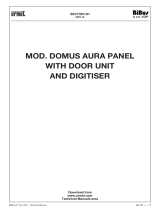
PROGRAMMING SUMMARY DIAGRAMS
This guide provides additional help for programming 2
nd
edition Bibus digitiser door units.
The following programming methods are recommended according to the complexity of the system and the required functions:
A. Systems with up to 3 main calling stations (without secondary systems or concierge switchboard):
1. Without staircase light function on button P1 (see diagram A1 page 8).
2. With staircase light function on button P1 (see diagram A2 page 9).
B. Systems with more than 3 main calling stations or main and secondary calling stations (see diagram B page 10).
Diagram A1
Programming procedure for systems with up to 3 main calling stations (no secondary stations or concierge switchboard) without stair lights
function on button P1.
(*) All data will be lost if the dip switches are moved also after ending the programming procedure.

sec.3e
−−−−
9
SINTHESI SLIM PANEL WITH DOOR UNIT AND DIGITISER
BIBUS 2
nd
Ed. VOP - Technical Manual
LOUDSPEAKING UNIT - SINTHESI SLIM
Dip switch position Main station number
Not defined
(for programming with
external keypad)
Station 1
Station 2
Station 3
The LED will light up
and a confirmation tone
will be heard
Set the main station number (1, 2 or 3)
by means of the dip switches (
*
)
on all door units
Hold the “Hall” button pressed
(PA; GND terminals) for the time
to be programmed
Press the programming button
on the door unit
Press the programming button
SIMPLIFIED PROGRAMMING
PROCEDURE
with stair lights function
Program door lock
activation time
(to be repeated
for all door units)
Assign station
number
The LED will go out
and a confirmation tone
will be heard
1 2
1 2
1 2
1 2
The door unit will acquire
the time and will beep
when the button
is released
The LED will light up
and a confirmation tone
will be heard
A confirmation beep
will be heard each time
the button is pressed
Go to the apartments in the booking
sequence, hold the door
opener button pressed and pick up
the door phone handset
Press all calling buttons for the door
phones to be programmed and note
the sequence down. DO NOT PRESS
BUTTON P1 (staircase lights) (
**
)
Press the programming button
on any door unit
Wait for 30 seconds
Program apartment
stations
(to be repeated
on any door unit
and all apartment
stations)
The LED will start blinking
and a confirmation tone
will be heard
The apartment station
will beep twice and the LED
will blink to confirm
programming.
The door unit LED
will go out
after programming
LOUDSPEAKING UNIT WITH INTEGRATED DIGITALIZER
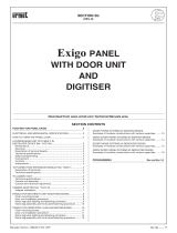
SINTHESI SLIM Ref. 1072/6
PROGRAMMING SUMMARY DIAGRAMS
Ref. 1072/6
Diagram A2
Programming procedure for systems with up to 3 main calling stations (no secondary stations or concierge switchboard) with stair lights function
on button P1.
(*) All data will be lost if the dip switches are moved also after ending the programming procedure.
(**) If you make a mistake, quit programming, hold the programming button pressed for longer than 3 seconds. The door unit default setting will
appear.

10
−−−−
sec.3e
SINTHESI SLIM PANEL WITH DOOR UNIT AND DIGITISER
BIBUS 2
nd
Ed. VOP - Technical Manual
LOUDSPEAKING UNIT - SINTHESI SLIM
Arrange dip switches
in this position
Connect the keypad and the adapter
to the door unit
FULL PROGRAMMING PROCEDURE
With 1032/65 keypad
and 1072/60 adapter
Program
SYSTEM TYPE
Program
STATION TYPE
Program
CODE FORMAT
Program
STATION NUMBER (ID)
1 2
(
*
)
Set up door units
for programming
using external keypad
and adapter (to be
repeated for all
door units).
The programming LED will light up and two
confirmation beeps will be heard
Define whether each calling station is main
or secondary
main
secondary
Define the code type to be used for apartment station
calls
numeric (0001÷9999)
with prefix (x001÷x999)
with suffix (000x÷999x)
Assign a different identification number to each
calling station
(x=number)
Possible numbers are:
1÷12 for main stations
0÷9 for second stations
The device must be programmed as 2nd edition only
if all the devices in the system are 2nd edition devices
1
st
edition
2
nd
edition
M 1
↵
M 2
↵
I 1
↵
F 1
↵
N x
↵
F 2
↵
F 3
↵
Go to the apartments in the booking
sequence, hold the door opener button
pressed and pick up
the door phone handset
Press calling buttons of the door phones
to be programmed and note the sequence
down. DO NOT PRESS the stair case
light button (P1 by default) if a button
has been reserved for this purpose
Wait for 30 seconds
The LED will start blinking and a confirmation tone
will be heard
Program apartment
stations
(to be repeated
on any door unit and
all apartment stations)
Programming procedure
(to be repeated
for each door unit)
Programming procedure
(to be repeated
for each door unit)
Program
PICK-UP TIME
Program
MINIMUM CONVERSATION TIME
(busy time)
Program
LOCK OPERATION TIME
Program
CODE-BUTTON ASSOCIATION
The apartment station will beep twice and the LED
will blink to confirm programming
The pick-up time is the maximum time from start
of a call for the user to answer the door phone
10 sec
20 sec
30 sec
40 sec
G 1
↵
G 4
↵
G 3
↵
G 2
↵
The minimum conversation time during which
the conversation cannot be interrupted by other users
10 sec
20 sec
30 sec
40 sec
O 1
↵
O 4
↵
O 3
↵
O 2
↵
A confirmation beep will be heard each time
the button is pressed
The relay controlling the door lock can be managed
in pulse mode (00) or stabile mode (from 1 to 30 s)
pulse
(xy=seconds)
xD y
↵
D 0
↵
0
I
↵
0
nm
P
↵
Each apartment station must be combined to a code
and calling button as follows:
xyzw = user code
nm = button number
C
xyzw
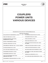
LOUDSPEAKING UNIT WITH INTEGRATED DIGITALIZER
SINTHESI SLIM Ref. 1072/6
PROGRAMMING SUMMARY DIAGRAMS
Ref. 1072/6
Diagram B
Programming procedure for systems with more than 3 main calling stations or with main and secondary calling stations.
(*) All data will be lost if the dip switches are moved also after ending the programming procedure.

sec.3e
−−−−
11
BIBUS 2
nd
Ed. VOP - Technical Manual
SINTHESI SLIM PANEL WITH DOOR UNIT AND DIGITISER
SINTHESI SLIM PANEL
Sinthesi Slim has a streamline shape specially designed for wall
installations. Designed according to the modular criteria and style that
characterise the Sinthesi line, the panel can be simply screwed to the
wall. No brickwork is needed.
The panel can be installed either vertically or horizontally. Furthermore,
the boxes can be coupled together using the specic spacers to
make panels of all types and conguration using a low number of
components.
The modules can be installed simply and interconnected by the
multipolar wires and plugs.
BUTTON MODULES
The following module versions are available:
• With 1 button Ref. 1072/31
• With 2 buttons Ref. 1072/32
• With 3 buttons Ref. 1072/33
• With 4 buttons Ref. 1072/34
Each module is provided with the following basic circuit for
connections:
NAME TAG REPLACEMENT
There are different types of name tags:
• White: for provisional writing with a felt-tip pen (standard)
• Anthracite: for engraving (standard)
• Red:
for staircase light button (door unit set-up modules only)
• Blue: for panel customisation (optional: Ref. 1145/65 consists
of blue name tags and frame headers).
Note: the engraving side is marked by the letter A on anthracite name
tags.
Proceedasfollowstoinsertthenametagsinthespecichousing:
1) Remove the frame (if installed) and remove the extractable front.
2) Fit the name tags.
3) Reposition the extractable front.
SINTHESI SLIM PANEL
BUTTON MODULES
OUTPUT
INPUT
MTT1
J1
J2
0
˜
12
˜
MTT2
0
˜
12
˜
TOP
Name tag
light power
Data line input
from other
button modules
Data line output
for connecting to
other button modules
or to the door unit
ROSSI
A
ROSSI
TO
P
TO
P
TO
P
TO
P
SINTHESI SLIM PANEL

12
−−−−
sec.3e
BIBUS 2
nd
Ed. VOP - Technical Manual
SINTHESI SLIM PANEL WITH DOOR UNIT AND DIGITISER
REPERTORY MODULES Ref. 1141/50
Repertory modules are normally used to indicate the house number or
contain other information.
Power terminals ~0 and ~12 to light the unit via LEDs.
The procedure for tting repertory tags is the same as that for the
name tags.
CAMERA MODULE Ref. 1741/30
The Sinthesi Slim Ref. 1741/30 black and white camera can be used
to make Bibus 2nd edition VOP video door phone systems.
The module is complete with:
• Fixed focus camera with built-in optics and shutter.
• Adjustable lens.
• Subject light.
DESCRIPTION OF TERMINALS
+TC Camera power positive in analogue systems
T Camera switch-on control
R2 Camera power positive
R1 Camera power negative
A Video signal
B Video signal earth
IMAGING ANGLES
Pivoting angles of the camera with respect to central position are:
VERTICAL + 10 TO -15°
HORIZONTAL + 10 TO -10°
CAMERA LENS DIRECTION ADJUSTMENT
After installation, the camera direction can be adjusted according to
the position of the framed subject. This operation may be carried
out manually after removing the frame and the extractable front by
adjusting the jointed mount directly from the front. The frame does not
need to be tipped and special tools are not required.
SINTHESI SLIM PANEL
BUTTON MODULES
A
188 188
Engraving side Blank tag
50
0
50
7
22
34
-40
-21
-12
+21
-46
+32
-32
+46
-21
HORIZONTAL
VERTICAL
+10°
+10°
0
-15°
-10°0
0
Measurements in centimetres
TO
P
TO
P
O
N
1
2
TO
P
TO
P
SINTHESI SLIM PANEL

sec.3e
−−−−
13
BIBUS 2
nd
Ed. VOP - Technical Manual
SINTHESI SLIM PANEL WITH DOOR UNIT AND DIGITISER
WALL FASTENING
A drilling template and hood is provided with the box. Install as shown
below if the panel is exposed to the elements.
Theentireinstallationsurfaceofthewallmustbeperfectlyat.
BOX UNION
The boxes may be joined by means of shims which double as
fairleads.
PAY ATTENTION TO DIRECTION OF INSERTION
INSTALLATION
Boxes with chassis and frames of the following versions must be
purchased for correct installation according to the module to be
installed:
• 2 modules Ref. 1141/52
• 3 modules Ref. 1141/53
You are advised to install the modules at the heights shown below
accordingtotherequiredsystemconguration.
Inanycase,considertheheightshowninthegureforfasteningthe
camera for correct installation of complex arrangement with several
modules. The height refers to the door unit in door phone systems.
SINTHESI SLIM PANEL
INSTALLATION
1,55 ÷ 1,60 m 1,55 ÷ 1,60 m
1,55 ÷ 1,60 m
1,55 ÷ 1,60 m
TOP
TOP
TOP
TOP
TOP
TOP
TOP
TOP
TOP
TOP
SINTHESI SLIM PANEL

14
−−−−
sec.3e
BIBUS 2
nd
Ed. VOP - Technical Manual
SINTHESI SLIM PANEL WITH DOOR UNIT AND DIGITISER
InthevideodoorsystemthecameraRef.1741/30mustbettedinthe
upper left position.
Vertical installation:tthedoorunitRef.1072/6underthecamera.
Horizontal installation:tthedoorunittotherightofthecamera.
In each case the wires must be let out in correspondence with the door
unit.
Maximum wire cross-section area must be 0.75 mm
2
. Use junction
boxes with wires of suitable cross-section area to connect to the
terminals if the wires used in the system are larger.
MODULE INSTALLATION
InthedoorphonesystemthedoorunitRef.1072/6mustbettedin
the upper left position.
SINTHESI SLIM PANEL
INSTALLATION
1,55 ÷ 1,60 m
TOP
TOP
TOP
TOP
TOP
TOP
TOP
TOP
Ref. 1072/6
1,55 ÷ 1,60 m
Ref. 1072/6
TOP
Sch. 1741/30
1,55 ÷ 1,60 m
TOP
TOP
TOP
TOP
TOP
TOP
TOP
TOP
Sch. 1741/30
Sch. 1072/6
Sch. 1072/6
1,55 ÷ 1,60 m
TOP
SINTHESI SLIM PANEL

sec.3e
−−−−
15
BIBUS 2
nd
Ed. VOP - Technical Manual
SINTHESI SLIM PANEL WITH DOOR UNIT AND DIGITISER
BASIC CIRCUIT VERTICAL INSTALLATION
BUTTON MODULE BASIC CIRCUIT CONNECTION DIAGRAM
Join the two terminals 0~ 12~ with a small cross-section area wire
(0.22 ÷ 0.5mm
2
).
TO
P
T
O
P
TOP
1
2
3
J2
J1
OUTPUT
INPUT
MTT1
J1
J2
0
˜
12
˜
MTT2
0
˜
12
˜
14 cm
40 cm
TOP
OUTPUT
INPUT
MTT1
J1
J2
0
˜
12
˜
MTT2
0
˜
12
˜
TOP
TOP
OUTPUT
INPUT
MTT1
J1
J2
0
˜
12
˜
MTT2
0
˜
12
˜
TOP
OUTPUT
J1
A
A
B
B
A
Basic circuit
Ref. 1072/6
Basic circuit
Ref. 1072/31...34
Basic circuit
Ref. 1072/31...34
Basic circuit
Ref. 1072/31...34
Inside the box
Between two boxes arranged side by side
SINTHESI SLIM PANEL
INSTALLATION
SINTHESI SLIM PANEL

16
−−−−
sec.3e
BIBUS 2
nd
Ed. VOP - Technical Manual
SINTHESI SLIM PANEL WITH DOOR UNIT AND DIGITISER
WIRING ON BOTTOM OF BOX
Cut the wires in the system exactly to the right length.
BASIC CIRCUIT HORIZONTAL INSTALLATION
FRAME AND MODULE ASSEMBLY
Join the two terminals 0~ 12~ with a small cross-section area wire
(0.22 ÷ 0.5mm
2
).
WIRING ON BOTTOM OF BOX
Cut the wires in the system exactly to the right length.
TOP
TOP
OUTPUT
INPUT
J1
J2
0
˜
12
˜
0
˜
12
˜
OUTPUT
INPUT
J1
J2
0
˜
12
˜
0
˜
12
˜
OUTPUT
INPUT
J1
J2
0
˜
12
˜
0
˜
12 ˜
TOP
TOP
CN1
A
B
+TC
T
R2
R1
M1M2
J1
J3
OUTPUT
INPUT
J1
J2
0
˜
12
˜
0
˜
12
˜
Areas not to be used
for passage of wires
Wire stay
J2
MTT1 MTT1
MTT1
MTT1
MTT2
MTT2
MTT2
MTT2
1741/301072/61072/31-/...-/34
1072/31-/...-/34 1072/31-/...-/341072/31-/...-/34
0
˜
12
˜
T
J1
MTT2
TO
P
TOP
T
O
P
1 2
3
J2
J1
OUTPUT
INPUT
MTT1
J1
J2
0
˜
12
˜
MTT2
0
˜
12
˜
OUTPUT
INPUT
MTT1
J1
J2
0
˜
12
˜
MTT2
0
˜
12
˜
TOP
OUTPUT
INPUT
MTT1
J1
J2
0
˜
12
˜
MTT2
0
˜
12
˜
TOP
TOP TOP
14 cm
40 cm
A
A
A
B
B
OUTPUT
J1
Basic circuit
Ref. 1072/6
Inside the box
Between two boxes arranged side by side
Basic
circuit
Ref. 1072/31...34
Basic circuit
Ref. 1072/31...34
TOP
TOP
TOP
TOP
OUTPUT
INPUT
J2
0
˜
12
˜
0
˜
12
˜
CN1
A
B
+TC
T
R2
R1
M1M2
J1
J2
J3
J4
OUTPUT
INPUT
J2
0
˜
12
˜
0
˜
12
˜
OUTPUT
INPUT
J1
J2
0
˜
12
˜
MTT2
0
˜
12
˜
OUTPUT
INPUT
J2
0
˜
12
˜
0
˜
12
˜
MTT1
MTT2
MTT1 MTT1
J5
MTT1
1741/30 1072/6
1072/31-/...-/34 1072/31-/...-/34
1072/31-/...-/34
J1
MTT2
J1
MTT2
J1
1072/31-/...-/34
Areas not to be used for passage of wires
Wire stay
SINTHESI SLIM PANEL
INSTALLATION
SINTHESI SLIM PANEL

sec.3e
−−−−
17
BIBUS 2
nd
Ed. VOP - Technical Manual
SINTHESI SLIM PANEL WITH DOOR UNIT AND DIGITISER
Fit the name tags on the removable front.
FRAME AND MODULE ASSEMBLY
Fit the module holder frame on the boxes.
Fit the modules on the module holder.
TO
P
TOP
OUTPUT
MT
T
1
J
1
J2
0
˜
12
˜
MT
T
2
0
˜
1
2
˜
TO
P
TOP
OUTPUT
MT
T
1
J
1
J2
0
˜
1
2
˜
MT
T
2
0
˜
1
2
˜
OUTPUT
M
TT
1
J1
J2
0
˜
1
2
˜
MT
T
2
0
˜
12
˜
OUTPUT
MT
T
1
J
1
J2
0
˜
12
˜
MT
T
2
0
˜
12
˜
T
O
P
T
O
P
TO
P
For Ref. 1141/53
boxes only
T
O
P
T
O
P
ROSSI
ROSSI
Engraving side
Blank tag
A
TO
P
TO
P
TO
P
TO
P
SINTHESI SLIM PANEL
INSTALLATION
SINTHESI SLIM PANEL

18
−−−−
sec.3e
BIBUS 2
nd
Ed. VOP - Technical Manual
SINTHESI SLIM PANEL WITH DOOR UNIT AND DIGITISER
Program the Ref. 1072/6 unit.
Adjust the camera orientation.
REMOVING MODULES FROM MODULE HOLDER
FRAME
TO
P
TO
P
O
N
1
2
TO
P
TO
P
TO
P
TO
P
O
N
1
2
TO
P
TO
P
O
N
1
2
TO
P
TO
P
TO
P
TO
P
OUTPUT
M
T
T1
J
1
J2
0
˜
1
2
˜
M
T
T
2
0
˜
12
˜
SINTHESI SLIM PANEL
INSTALLATION
SINTHESI SLIM PANEL

sec.3e
−−−−
19
BIBUS 2
nd
Ed. VOP - Technical Manual
SINTHESI SLIM PANEL WITH DOOR UNIT AND DIGITISER
FRAME ASSEMBLY
SINTHESI SLIM PANEL
INSTALLATION
SINTHESI SLIM PANEL
Fit the frame on the module holder.
TO
P
TO
P

20
−−−−
sec.3e
BIBUS 2
nd
Ed. VOP - Technical Manual
SINTHESI SLIM PANEL WITH DOOR UNIT AND DIGITISER
SINTHESI SLIM PANEL
DIMENSIONS
Note: H= 214 and 304 indicates total height relative to 2 and 3 module versions.
379 mm
H
214 / 304 mm
252 mm
H
214 / 304 mm
125 mm35 mm
H
214 / 304 mm
H
214 / 304 mm
H
214 / 304 mm
H
214 / 304 mm
379 mm
TOP
TOP
TOP
TOP
TOP
TOP
TOP
TOP
TOP
TOP
TOP
TOP
252 mm125 mm
SINTHESI SLIM PANEL
/