Page is loading ...

sec.1a
−−−−
1
START
BIBUS 2
nd
Ed. VOP - Technical Manual
SECTION 1A
PROGRAMMING
PROGRAMMING PROCEDURE FOR
DOOR UNITS WITH DIGITISER 2
SIMPLIFIED PROGRAMMING ..........................................................2
Station number (ID) ....................................................................... 2
Electrical lock time .......................................................................2
Door phone programming ............................................................2
Associating 2/3 door phones in parallel in 2nd edition
systemsusingthesimpliedprogrammingprocedure ................ 2
COMPLETE PROGRAMMING WITH EXTERNAL DEVICE ...............2
System type ..................................................................................2
Station type ..................................................................................3
Code format..................................................................................3
Station number (ID) ....................................................................... 3
Off-hook waiting time ...................................................................3
Minimum conversation time (busy) ............................................... 3
Door lock activation time ..............................................................3
Code button association ..............................................................3
Programming door phones in 2nd edition systems
using the programming adapter ...................................................3
Associating 2/3 door phones in parallel in 2nd edition systems
using the programming adapter ...................................................4
Adding new users in 2nd edition systems using
the programming adapter ............................................................. 4
Programming door phones in 1st edition systems
using the programming adapter ...................................................4
Associating 2 door phones in parallel in 1st edition systems
using the programming adapter ...................................................4
Adding new users in 1st edition systems using
the programming adapter ............................................................. 4
PROGRAMMING OVERVIEW DIAGRAMS
FOR DOOR UNITS WITH DIGITISER ...............................................5
Download from www.urmet.com Technical Manuals area.
SECTION CONTENTS
CALLING MODULE PROGRAMMING PROCEDURE 8
PROGRAMMING VIA Ref. 1032/65 KEYBOARD .............................8
PROGRAMMING VIA LOCAL KEYPAD ............................................8
Programming parameters ............................................................. 8
PROGRAMMING VIA PC ................................................................12
ADDITIONAL INFORMATION .........................................................12

PROGRAMMING
2
−−−−
sec.1a
START
BIBUS 2
nd
Ed. VOP - Technical Manual
PROGRAMMING PROCEDURE FOR DOOR
UNITS WITH DIGITISER
The door unit can be programmed in systems with up to three
main calling stations without secondary stations simply by means
of the LED button and the two dip switches without using external
devices. In complex systems and for special programming
needs, the device can be programmed with adapter Ref. 1072/60
to be inserted in the specic dedicated minidin connector. The
programming adapter must be connected to the programming
keyboard Ref. 1032/65.
The system must be powered for programming.
SIMPLIFIED PROGRAMMING
The door unit and the door phones can be programmed without external
devices in 2nd edition systems consisting of main calling stations only
(up to three). The following parameters can be programmed in this
case:
• Main station number: with dip-switch (1, 2, 3).
• Lock activation time: with LED button (1-30s).
• Door phone programming with LED button (predetermined user
codes).
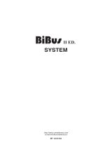
STATION NUMBER (ID)
The two dip-switches determine the main station number as shown
in the following table:
ELECTRICAL LOCK TIME
Press the programming button and wait for the respective LED to
come on.
Beeps will be repeatedly generated if there are other stations with
the same ID. Press the button again to quit the operation, correct
the mistake with the dip-switches and repeat the operation. Hold the
“hall” button pressed for the time to be programmed (up to 30 s). The
doorunitwillacquirethevalueandaconrmationbeepwillbeheard.
Press the programming button to return to normal operation.
The name tag light LEDs will go out when then electrical lock is
operated.
DOOR PHONE PROGRAMMING
The door unit is programmed by default at the factory.
Consequently, the code-button association phase can be skipped in
systems without secondary units. In this case, go to the door phone
programming procedure directly. The procedure consists of two
steps:
A. Door phone booking (to be made on a calling station).
B. Door phone programming.
A: Door phone booking (to be made on a calling station)
Press the programming button and wait for the respective LED
to come on. Press the user buttons to be associated with the
door phones once. The booking sequence according to which the
buttons are pressed must be the same as the order in which the
operator will go to the apartments.
DO NOT press the switchboard call button and the staircase light
button (P1).
B: Door phone programming
1. Wait for 30s until the LED starts blinking.
2. Gototherstbookeduser,holdthebuttonpressedandliftthe
doorphonehandset.Twoconrmationbeepswillbeheardand
theLEDwillashtoindicatethatithasbeenprogrammed.
3. Go to the other booked users and repeat the operations.
Refer to the supplied sheet to remember the code/button association
sequence.
IMPORTANT: The LED will start blinking if the buttons are not booked
and no operation is carried out for 30 seconds during the programming
procedure. In this case, press the programming button to quit
programming. If required, press it again to resume programming.
ASSOCIATING 2/3 DOOR PHONES IN PARALLEL
IN 2ND EDITION SYSTEMS USING THE SIMPLIFIED
PROGRAMMING PROCEDURE
To install two or three door phones in one apartment and make them
both ring when a call is received, press the button related to the user
twice or three times with the door phones in parallel when booking
the door phones.
When you reach the apartment where the parallel door phones
are installed according to the programming sequence, repeat the
programming sequence on both door phones.
COMPLETE PROGRAMMING WITH EXTERNAL
DEVICE
Insertionoftheprogrammingdeviceisconrmedbytwobeepsand
by the led lighting.
Arrangethedipswitchesinthepositionshowninthefollowinggure
while programming with external device:
All data will be lost if the dip switches are moved also after ending the
programming procedure.
Insertionoftheprogrammingdeviceisconrmedbytwobeepsand
by the led lighting.
Parameters can be programmed or reprogrammed in any order until
thekeyboardisextracted.Twobeepswillbeheardtoconrmdata
programming. A KO signal (two beeps, the second of which at a lower
frequency) will be heard if the programming is not valid.
Repetitive beeps will be heard in programming if other modules with
the same ID are present.
Press the button
to silence the signal.
You are advised to program the data in the following order for the
sake of simplicity.
SYSTEM TYPE
The digitiser can be congured as 1st edition or 2nd edition. The
digitiser must be programmed as 1st edition if there is even only
one 1st edition device in the system (when replacing parts in old
systems). The device must be programmed as 2nd edition when
all the devices in the system are 2nd edition.
Dip-Switch position Main station number
Not defined (for programming
with an external keyboard)
Station 1
Station 2
Station 3
1 2
ON
1 2
ON
1 2
ON
1 2
ON
1 2
ON
PROGRAMMING PROCEDURE FOR DOOR UNITS WITH DIGITISER
SIMPLIFIED PROGRAMMING
COMPLETE PROGRAMMING WITH EXTERNAL DEVICE
PROGRAMMING PROCEDURE FOR DOOR UNITS WITH DIGITISER
SEQUENZA DI ASSOCIAZIONE
ASSOCIATION SEQUENCE
N° DELLA POSTAZIONE (ID):
CALL MODULE NUMBER (ID):
SEQ. NOMINATIVO PULSANTE / CODICE PIANO VARIE
USER NAME PUSHBUTTON / CODE FLOOR VARIOUS
1
2
3
4
5

PROGRAMMING
sec.1a
−−−−
3
START
BIBUS 2
nd
Ed. VOP - Technical Manual
Letter“M”identiesthetypeofsystem:
press M1 ↵ to program 1st edition
press M2 ↵ to program 2nd edition
The device will repeatedly beep if there are other modules with the
same ID. Press the button to silence the signal.
The two dip-switches must not be in the ON position to program this
parameter successfully.
STATION TYPE
Thedigitisercanbeconguredasamainstationorasasecondary
station. A secondary digitiser can be used to send calls to internal
stations in the riser but cannot be used to call the switchboard. In
the case of 1st edition systems, the digitiser will be automatically
congured as a main station and should not be changed.
Letter“I”identiesthetypeofstation:
press I0 ↵ to program the main station
press I1 ↵ to program the secondary station
The device will repeatedly beep if there are other modules with the
same ID. Press the button to silence the signal.
The two dip-switches must not be in the ON position to program this
parameter successfully.
CODE FORMAT
The digitiser can be used to call users with numeric codes (0001-
9999), alphanumeric codes with alphabetic prex (x000-x999) and
alphanumericcodeswithalphabeticsufx(000x-999x).Lettersfrom
A to J can be used.
Letter“F”identiesthetypeofprogrammablecode:
numeric code F1 ↵
codewithalphabeticprex: F2↵
codewithalphabeticsufx: F3↵
1st edition system: this programming is not required.
STATION NUMBER (ID)
A number from 1 to 12 is assigned to each main calling station. A
number from 0 to 9 is assigned to each secondary station.
The secondary number is in the range from A to J in systems with
alphabeticprex.
Letter“N”identiesthestationnumber:
x station number: Nx ↵
A to J programmed on a secondary station will automatically be
reprogrammedasaprexcodeformat.IDfrom0to9onasecondary
station will automatically be reprogrammed as a numeric code
format.
The two dip-switches must not be in the ON position to program this
parameter successfully.
1st edition system: the station number must be in the range from 1
to 12 (there are not secondary stations in the system). Assign F as
station number to use the clone function.
OFF-HOOK WAITING TIME
The off-hook waiting time is the maximum time of a call in which the
user can answer the door phone.
All other calling stations will be engaged during this time. All devices
in the system must have the same off-hook waiting time.
Letter “G” identities the off-hook waiting time:
10s waiting time: G1 ↵
20s waiting time: G2 ↵
30s waiting time: G3 ↵
40s waiting time: G4 ↵
MINIMUM CONVERSATION TIME (BUSY)
When a user is called and answers the door phone, all other call
stations will be busy for the minimum programmed conversation
time. A communication that has just started cannot be interrupted.
All devices in the system must have the same minimum conversation
time (busy time).
Letter “O” identities the off-hook waiting time:
10s busy: O1 ↵
20s busy: O2 ↵
30s busy: O3 ↵
40s busy: O4 ↵
DOOR LOCK ACTIVATION TIME
The relay controlling the door lock can be managed in pulse mode
(approximately 600 ms) or stabile mode (from 1 to 30 s).
Letter “D” identities the lock activation time:
door lock pulse: D00 ↵
door lock xy seconds: Dxy ↵
The name tag light LEDs will go out when then electrical lock is
operated.
CODE BUTTON ASSOCIATION
This is the step in which user codes to be programmed are associated
to each button connected to the digitiser.
The call code sequence is:
Cxyzw Pnm ↵
Where xyzw is the user code and nm is the calling station button
number.
The user code xyzw can have the following values
• 0001-9999: for numeric code formats
• x000-x999: foralphabeticprexcodeformats(xfromAtoJ)
• 000x-999x: foralphabeticsufxcodeformats(xfromAtoJ)
• 0000: for direct calls to switchboard in day mode.
• LLLL: for “staircase lights” function.
The button number nm depends on the position of the terminal to
which it is connected.
Once a code is programmed, press button ↵ to automatically program
call code xyzw+1 on button nm+1. For example, the calling sequence
C1000P01 ↵ ↵ ↵ will program code 1000 on button 01, code 1001
button 02 and code 1002 on button 03.
1st edition system: this programming is not required.
PROGRAMMING DOOR PHONES IN 2ND EDITION
SYSTEMS USING THE PROGRAMMING ADAPTER
The door phone programming sequence consists of two steps:
A. Door phone booking (to be made on a calling station).
B. Door phone programming (to be made in the apartments).
A: Door phone booking
1. InsertadapterRef.1072/60inthespecicminidinconnector.
2. Press the user buttons to be associated with the door phones
once. The booking sequence according to which the buttons are
pressed must be the same as the order in which the operator will
go to the apartments. DO NOT press the switchboard call button
or the “staircase lights” function.
3. A beep will be heard after 30 seconds from last pressing a user
button (end of booking).
4. Leave the adapter Ref. 1072/60 in the digitiser and go to the
apartments to program the door phones.
B: Door phone programming
1. Gototherstbookeduser,holdthebuttonpressedandliftthe
doorphonehandset.Twoconrmationbeepswillbeheardand
theLEDwillashtoindicatethatithasbeenprogrammed.
PROGRAMMING PROCEDURE FOR DOOR UNITS WITH DIGITISER
COMPLETE PROGRAMMING WITH EXTERNAL DEVICE
PROGRAMMING PROCEDURE FOR DOOR UNITS WITH DIGITISER

PROGRAMMING
4
−−−−
sec.1a
START
BIBUS 2
nd
Ed. VOP - Technical Manual
SEQUENZA DI ASSOCIAZIONE
ASSOCIATION SEQUENCE
N° DELLA POSTAZIONE (ID):
CALL MODULE NUMBER (ID):
SEQ. NOMINATIVO PULSANTE / CODICE PIANO VARIE
USER NAME PUSHBUTTON / CODE FLOOR VARIOUS
1
2
3
4
5
2. Go to the other booked users and repeat the operations.
Refer to the supplied sheet to remember the code/button association
sequence.
ASSOCIATING 2/3 DOOR PHONES IN PARALLEL IN
2ND EDITION SYSTEMS USING THE PROGRAMMING
ADAPTER
To install two or three door phones in one apartment and make them
both ring when a call is received, press the button related to the user
twice or three times with the door phones in parallel when booking
the door phones.
When you reach the apartment where the parallel door phones
are installed according to the programming sequence, repeat the
programming sequence on both door phones.
ADDING NEW USERS IN 2ND EDITION SYSTEMS
USING THE PROGRAMMING ADAPTER
Insert the programming adapter in the digitiser connector and program
the user code of the button which will call the unit. Press this button to
book programming and go to the user to program the door phone.
PROGRAMMING DOOR PHONES IN 1ST EDITION
SYSTEMS USING THE PROGRAMMING ADAPTER
The door phone programming sequence consists of two steps:
A. Door phone booking (to be made on a calling station).
B. Door phone programming (to be made in the apartments).
A: Door phone booking
1. InsertadapterRef.1072/60inthespecicminidinconnector.
2. Press the user buttons to be associated with the door phones
once. The booking sequence according to which the buttons are
pressed must be the same as the order in which the operator will
go to the apartments.
3. A beep will be heard after 30 seconds from last pressing a user
button (end of booking).
4. Leave the adapter Ref. 1072/60 in the digitiser and go to the
apartments to program the door phones.
B: Door phone programming
1. Gototherstbookeduser,holdthebuttonpressedandliftthe
doorphonehandset.Twoconrmationbeepswillbeheardand
theLEDwillashtoindicatethatithasbeenprogrammed.
2. Go to the other booked users and repeat the operations.
Refer to the supplied sheet to remember the code/button association
sequence.
The entire operation (booking and programming) must be
repeated for each digitiser in the system, unless the “Clone”
function (see below) is used.
ASSOCIATING 2 DOOR PHONES IN PARALLEL IN
1ST EDITION SYSTEMS USING THE PROGRAMMING
ADAPTER
To install two door phones in one apartment and make them both ring
when a call is received, press the button related to the user twice with
the door phones in parallel when booking the door phones.
When you reach the apartment where the parallel door phones
are installed according to the programming sequence, repeat the
programming sequence on both door phones.
ADDING NEW USERS IN 1ST EDITION SYSTEMS
USING THE PROGRAMMING ADAPTER
Insert the programming adapter in the specic digitiser connector.
Press this button to book programming and go to the user to program
the door phone.
The entire operation (booking and programming) must be
repeated for each digitiser in the system, unless the “Clone”
function (see below) is used.
Using the “clone” function with the programming adapter
A single association between calling stations and respective door
phones can be made in 1st edition systems without switchboard and
without door open signal function.
The remaining calling stations must be clones of the rst station
(master) providing the wiring between push-button panel buttons,
calling station terminals and expansion modules in the “Master”
station are repeated exactly. To enable this function:
• Denethemasterpositionasaddress“1”;(thepositiononwhichto
make the association).
• Deneallotherstationsasaddress“F”.
SEQUENZA DI ASSOCIAZIONE
ASSOCIATION SEQUENCE
N° DELLA POSTAZIONE (ID):
CALL MODULE NUMBER (ID):
SEQ. NOMINATIVO PULSANTE / CODICE PIANO VARIE
USER NAME PUSHBUTTON / CODE FLOOR VARIOUS
1
2
3
4
5
PROGRAMMING PROCEDURE FOR DOOR UNITS WITH DIGITISER
COMPLETE PROGRAMMING WITH EXTERNAL DEVICE
PROGRAMMING PROCEDURE FOR DOOR UNITS WITH DIGITISER

PROGRAMMING
sec.1a
−−−−
5
START
BIBUS 2
nd
Ed. VOP - Technical Manual
PROGRAMMING OVERVIEW DIAGRAMS FOR DOOR UNITS WITH DIGITISER
This guide provides additional help for programming 2
nd
edition Bibus digitiser door units.
The following programming methods are recommended according to the complexity of the system and the required functions:
A. Systems with up to 3 main calling stations (without secondary systems or concierge switchboard):
1. Without staircase light function on button P1 (see diagram A1 page 5).
2. With staircase light function on button P1 (see diagram A2 page 6).
B. Systems with more than 3 main calling stations or main and secondary calling stations (see diagram B page 7).
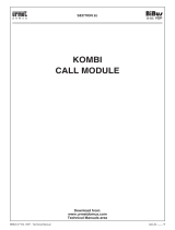
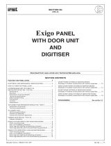
Diagram A1
Programming procedure for systems with up to 3 main calling stations (no secondary stations or concierge switchboard) without stair lights
function on button P1.
(*) All data will be lost if the dip switches are moved also after ending the programming procedure.
Dip switch position Main station number
Not defined
(for programming with
external keypad)
Station 1
Station 2
Station 3
The LED will light up and
a confirmation tone
will be heard
Go to the apartments in the booking
sequence, hold the door opener button
pressed and pick up the door
phone handset.
Set the main station number (1, 2 or 3)
by means of the dip switches (
*
)
on all door units
Hold the “Hall” button pressed
(PA; GND terminals) for the time
to be programmed
Press calling buttons of the door
phones to be programmed
and note the sequence down
Press the programming button
on the door unit
Wait for 30 seconds
Press the programming button
Press the programming button
SIMPLIFIED PROGRAMMING
PROCEDURE
without stair lights function
Program door lock
activation time
(to be repeated
for all door units)
Assign station
number
The door unit will acquire
the time and will
beep when the button
is released
The LED will go out
and a confirmation
tone will be heard
The LED will go out
and a confirmation tone
will be heard.
The LED will light up
and a confirmation
tone will be heard
The LED will start blinking
and a confirmation
tone will be heard
The LED will light up
and a confirmation tone
will be heard
The door unit will beep
A confirmation beep
will be heard each
time the button is pressed
Program apartment
stations
(to be repeated
on any door unit
and all apartment
stations)
1 2
1 2
1 2
1 2
Press the programming button
on the door unit
Press the programming button
Assign calling code
to button P1
(to be repeated
for all door units).
Press button P1
The apartment station
will beep twice and the LED
will blink to confirm
programming.
The door unit LED
will go out
after programming
PROGRAMMING PROCEDURE FOR DOOR UNITS WITH DIGITISER
PROGRAMMING OVERVIEW DIAGRAMS FOR DOOR UNITS WITH DIGITISER
PROGRAMMING PROCEDURE FOR DOOR UNITS WITH DIGITISER

PROGRAMMING
6
−−−−
sec.1a
START
BIBUS 2
nd
Ed. VOP - Technical Manual
Diagram A2
Programming procedure for systems with up to 3 main calling stations (no secondary stations or concierge switchboard) with stair lights
function on button P1.
(*) All data will be lost if the dip switches are moved also after ending the programming procedure.
(**) If you make a mistake, quit programming, hold the programming button pressed for longer than 3 seconds. The door unit default setting will
appear.
Dip switch position Main station number
Not defined
(for programming with
external keypad)
Station 1
Station 2
Station 3
The LED will light up
and a confirmation tone
will be heard
Set the main station number (1, 2 or 3)
by means of the dip switches (
*
)
on all door units
Hold the “Hall” button pressed
(PA; GND terminals) for the time
to be programmed
Press the programming button
on the door unit
Press the programming button
SIMPLIFIED PROGRAMMING
PROCEDURE
with stair lights function
Program door lock
activation time
(to be repeated
for all door units)
Assign station
number
The LED will go out
and a confirmation tone
will be heard
1 2
1 2
1 2
1 2
The door unit will acquire
the time and will beep
when the button
is released
The LED will light up
and a confirmation tone
will be heard
A confirmation beep
will be heard each time
the button is pressed
Go to the apartments in the booking
sequence, hold the door
opener button pressed and pick up
the door phone handset
Press all calling buttons for the door
phones to be programmed and note
the sequence down. DO NOT PRESS
BUTTON P1 (staircase lights) (
**
)
Press the programming button
on any door unit
Wait for 30 seconds
Program apartment
stations
(to be repeated
on any door unit
and all apartment
stations)
The LED will start blinking
and a confirmation tone
will be heard
The apartment station
will beep twice and the LED
will blink to confirm
programming.
The door unit LED
will go out
after programming
PROGRAMMING PROCEDURE FOR DOOR UNITS WITH DIGITISER
PROGRAMMING OVERVIEW DIAGRAMS FOR DOOR UNITS WITH DIGITISER
PROGRAMMING PROCEDURE FOR DOOR UNITS WITH DIGITISER

PROGRAMMING
sec.1a
−−−−
7
START
BIBUS 2
nd
Ed. VOP - Technical Manual
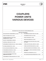
Diagram B
Programming procedure for systems with more than 3 main calling stations or with main and secondary calling stations.
(*) All data will be lost if the dip switches are moved also after ending the programming procedure.
PROGRAMMING PROCEDURE FOR DOOR UNITS WITH DIGITISER
PROGRAMMING OVERVIEW DIAGRAMS FOR DOOR UNITS WITH DIGITISER
Arrange dip switches
in this position
Connect the keypad and the adapter
to the door unit
FULL PROGRAMMING PROCEDURE
With 1032/65 keypad
and 1072/60 adapter
Program
SYSTEM TYPE
Program
STATION TYPE
Program
CODE FORMAT
Program
STATION NUMBER (ID)
1 2
(
*
)
Set up door units
for programming
using external keypad
and adapter (to be
repeated for all
door units).
The programming LED will light up and two
confirmation beeps will be heard
Define whether each calling station is main
or secondary
main
secondary
Define the code type to be used for apartment station
calls
numeric (0001÷9999)
with prefix (x001÷x999)
with suffix (000x÷999x)
Assign a different identification number to each
calling station
(x=number)
Possible numbers are:
1÷12 for main stations
0÷9 for second stations
The device must be programmed as 2nd edition only
if all the devices in the system are 2nd edition devices
1
st
edition
2
nd
edition
M 1
↵
M 2
↵
I 1
↵
F 1
↵
N x
↵
F 2
↵
F 3
↵
Go to the apartments in the booking
sequence, hold the door opener button
pressed and pick up
the door phone handset
Press calling buttons of the door phones
to be programmed and note the sequence
down. DO NOT PRESS the stair case
light button (P1 by default) if a button
has been reserved for this purpose
Wait for 30 seconds
The LED will start blinking and a confirmation tone
will be heard
Program apartment
stations
(to be repeated
on any door unit and
all apartment stations)
Programming procedure
(to be repeated
for each door unit)
Programming procedure
(to be repeated
for each door unit)
Program
PICK-UP TIME
Program
MINIMUM CONVERSATION TIME
(busy time)
Program
LOCK OPERATION TIME
Program
CODE-BUTTON ASSOCIATION
The apartment station will beep twice and the LED
will blink to confirm programming
The pick-up time is the maximum time from start
of a call for the user to answer the door phone
10 sec
20 sec
30 sec
40 sec
G 1
↵
G 4
↵
G 3
↵
G 2
↵
The minimum conversation time during which
the conversation cannot be interrupted by other users
10 sec
20 sec
30 sec
40 sec
O 1
↵
O 4
↵
O 3
↵
O 2
↵
A confirmation beep will be heard each time
the button is pressed
The relay controlling the door lock can be managed
in pulse mode (00) or stabile mode (from 1 to 30 s)
pulse
(xy=seconds)
xD y
↵
D 0
↵
0
I
↵
0
nm
P
↵
Each apartment station must be combined to a code
and calling button as follows:
xyzw = user code
nm = button number
C
xyzw
PROGRAMMING PROCEDURE FOR DOOR UNITS WITH DIGITISER

PROGRAMMING
8
−−−−
sec.1a
START
BIBUS 2
nd
Ed. VOP - Technical Manual
CALLING MODULE PROGRAMMING PROCEDURE
PROGRAMMING VIA Ref. 1032/65 KEYBOARD
PROGRAMMING VIA LOCAL KEYPAD
CALLING MODULE PROGRAMMING
PROCEDURE
The module can be programmed in three ways when the system is
powered:
1 Via external keyboard ref. 1032/65 (recommended method).
2 Via local numeric keypad without opening the frame. The
programming password is required for this operation.
3 Via PC connection.
Repetitive beeps and a message on the display in programming will
signal that other modules with the same ID are present. Change the
station number (ID) in this case.
PROGRAMMING VIA Ref. 1032/65 KEYBOARD
Programming mode is entered automatically by connecting the
external keyboard to the calling module.
Programming mode is quitted by disconnecting the external keyboard
in any menu. All previously entered data will remain valid.
See “PROGRAMMING PARAMETERS”.
PROGRAMMING VIA LOCAL KEYPAD
Programming mode can be accessed in two ways.
• The conguration access password is known (the default
password is “9999”): enter “00” followed by the 4-digit password
and press .
The following message will appear if the password is wrong:
Password entry will be jammed for a time which increases with the
number of failed attempts after the third attempt.
• The password is not known: open the frame and press the
programming button on the back.
The red programming button on the back of the unit can be pressed
in any programming menu. The data entered to this time will be
valid. Press for three seconds to go back to the previous menu.
Press for three seconds in the main menu to quit programming.
Normal operation is automatically restored if no buttons are pressed
for over three minutes.
PROGRAMMING PARAMETERS
Refer to the local keypad programming method for programming
menu operative descriptions.
The following table shows the operative differences for programming
via Ref. 1032/65 keyboard.
The main menu will appear on the display when programming mode
is accessed:
(2nd
e d i t i o n
only)
Use and buttons to scroll the menus. Select the required menu
and press
toconrm.
The module will check for other devices programmed with the
same number (ID) in the system when accessing programming
mode and during programming. The following error message
will appear if other modules with the same ID are tted (which
will certainly be the case of a system with more than one call
station):
INCORRECT
PASSWORD
Function Programming Programming
via local keypad
via external keyboard
Select menu Buttons and Buttons ← and →
OK (enter) Button Button ↵
Escape
Button
(one menu up)
pressed for 3s
Button
White space Separate characters Button SP
Backspace (for correction) Separate characters Button BS
Select special characters Separate characters Button /
Delete booking of
code to be associated Button Button BS
Main Menu
BUSY TIME ↓↑
Main Menu
Type of code ↓↑
Main Menu
Lock rel. codes ↓↑
Main Menu
Door op. time ↓↑
Main Menu
Codes/names ↓↑
Main Menu
Mod. password ↓↑
Main Menu
Association ↓↑
Main Menu
Edition ↓
Main Menu
Cal Module n
o
↓↑
Main Menu
C. Module Type ↓↑
Main Menu
Language ↓↑
Main Menu
Switchb. call ↑
EXISTING
CALL MODULE N°.
CALLING MODULE PROGRAMMING PROCEDURE

PROGRAMMING
sec.1a
−−−−
9
START
BIBUS 2
nd
Ed. VOP - Technical Manual
CALLING MODULE PROGRAMMING PROCEDURE
PROGRAMMING VIA LOCAL KEYPAD
EDITION
Themodulecanbeconguredasa1steditionor2ndeditiondevice.
The module must be programmed as 1st edition if there is even
only one 1st edition device in the system (when replacing parts
in old systems). The device must be programmed as 2nd edition
when all the devices in the system are 2nd edition.
The following message will appear on the display:
(2nd
e d i t i o n
only)
Use and buttons to select and
buttontoconrm.
The system will automatically go back to the main menu after a
conrmationtone.
LANGUAGE
The following message will appear on the display:
Use and buttons to select and
buttontoconrm.
The system will automatically go back to the main menu after a
conrmationtone.
TYPE OF STATION
Themodulecanbecongured asamainstationorasasecondary
station. A secondary module can be used to send calls to internal
stations in the riser but cannot be used to call the switchboard. This
programming step will not appear in 1st edition systems.
The following message will appear on the display:
Use and buttons to select and
buttontoconrm.
The system will automatically go back to the main menu after a
conrmationtone.
STATION NUMBER (ID)
A number from 1 to 12 is assigned to each main calling station.
A number from 0 to 9 is assigned to each secondary station. The
secondary number is in the range from A to J in systems with
alphabeticprex.
A to J programmed on a secondary station will automatically be
reprogrammedasaprexcodeformat.IDfrom0to9onasecondary
station will automatically be reprogrammed as a numeric code
format.
The following message will appear on the display:
Enter the station number and press
toconrm.Press to cancel
the entry.
The system will automatically go back to the main menu after a
conrmationtone.
1st edition systems: the station number must be in the range from 1
to 12 (there are not secondary stations in the system). Assign 15 as
station number to use the clone function.
BUSY TIME
The busy time is split into two sub-menus.
The following message will appear on the display:
Use and buttons to select the submenu and
button to
conrm.
PICK-UP TIME
The pick-up time is the maximum time from start of a call for the user
to answer the door phone. All other calling stations will be engaged
during this time.
All devices in the system must have the pick-up time.
The following message will appear on the display:
Use and buttons to select and
buttontoconrm.
The system will automatically go back to the main menu after a
conrmationtone.
MINIMUM CONVERSATION TIME (BUSY)
When a user is called and answers the door phone, all other call
stations will be busy for the minimum programmed conversation time.
A communication that has just started cannot be interrupted.
All devices in the system must have the same minimum conversation
time (busy time).
The following message will appear on the display:
Use and buttons to select and
buttontoconrm.
The system will automatically go back to the main menu after a
conrmationtone.
DOOR LOCK ACTIVATION TIME
The relay controlling the door lock can be managed in pulse mode
(approximately 500 ms) or stabile mode (from 1 to 30 s).
The following message will appear on the display:
Enter the number of seconds and press to conrm. Press
to
cancel the entry.
The system will automatically go back to the main menu after a
conrmationtone.
DOOR OPENER CODES
The eight generic door opener codes can be stored in sequence.
== BUSY TIME ==
PICK-UP TIME ↓
== BUSY TIME ==
BUSY TIME ↑
PICK-UP TIME: 20s
<10><20><30><40>
BUSY TIME: 20s
<10><20><30><40>
Edition: II ED
<I ED> <II ED>
== Language ==
Italiano ↓
C. MOD. TYPE:
<MA.> <SEC>
= Station n° =
Station: 1
= Door op. time =
0 seconds
CALLING MODULE PROGRAMMING PROCEDURE

PROGRAMMING
10
−−−−
sec.1a
START
BIBUS 2
nd
Ed. VOP - Technical Manual
CALLING MODULE PROGRAMMING PROCEDURE
PROGRAMMING VIA LOCAL KEYPAD
The following message will appear on the display:
Enter the 4-digit code and press toconrm.Press to cancel the
entry. The system automatically prepares to enter the second code
afteraconrmationtone.
The system will automatically return to the main menu at the end of
programming. Alternatively, press for three seconds to go back to
the main menu.
CODE TYPE
The module can be used to call users with numeric codes (0001-
9999), alphanumeric codes with alphabetic prex (x000-x999) and
alphanumericcodeswithalphabeticsufx(000x-999x).Lettersfrom
A to J can be used.
The following message will appear on the display:
Use and buttons to select the Code Type and
button to
conrm.
CODES/NAMES
The names and respective codes can be programmed in this menu.
The following message will appear on the display:
Use and buttons to select the submenu and
button to
conrm.
ENTER DATA
The user codes and respective names and personal door opener
codes can be programmed in this sub-menu.
Therstfreepositioninthe250itemtablewillappear(oneitemfor
each user):
Enter the numeric or alphanumeric code formed by a variable number
of digits from 1 to 4 and press toconrm.Press to correct.
Press for longer than three seconds to go back to the previous
menu.
The same code can be entered in two or three positions in an apartment
where two or three door phones are connected in parallel (you are
advised to use adjacent positions to simplify the association).
The following will appear on the display after entering the code:
The name can be entered at a later time. In this case, press
to enter
the new code. Proceed as follows if the user name is known. Press
and on the calling module keypad to seek the required character.
The cursor will shift right by one position to enter a new character
after approximately one second if no other button is pressed. Press
to delete the last entered character. Use programming keyboard
1032/65 to considerably facilitate entry of names.
The same name can be assigned to different codes.
Enter the name and press
to enter the respective door opener
code.
The following message will appear on the display:
Enter the personal door opener code and press toconrm.The
general code programmed during the “Door opener code” phase
cannot be entered. Press without entering a code to skip assigning
a door opener code to the user.
EDIT DATA
The data related to the entered users can be edited in this sub-menu.
The following search criteria can be applied:
• Search by position in table (1-250).
• Search by name.
The following message will appear on the display:
Use the arrows to select the search criteria and press
toconrm.
SEARCH BY POSITION
This sub-menu can be used either to edit the user code, name or door
opener code in a certain position in the table or to delete the record.
The following message will appear on the display:
Use the arrows to select the position and press
toconrm.
At this point, you can:
• Delete the record by pressing (or bs button on keyboard 1032/65
todeletethecode);aconrmationwindowwillappearbeforethe
record is deleted from the table.
• Change the user code: enter a new code and press toconrm
Lock rel. codes
1° Code:
Position: 1
Code:
= Code Type =
Num. 1.9999 ↓
= Code Type =
Suff. 000x.999x ↑
= Code Type =
Pref. x000.x999 ↓↑
= Code/Name =
Enter data ↓
= Code/Name =
Clear all ↑
= Code/Name =
Modify data ↓↑
Code 1001 Name:
Code Lock rel.
Modify data
Search by pos. ↓
Modify data
Search by name ↑
Position: 1
Code: 1001
CALLING MODULE PROGRAMMING PROCEDURE

PROGRAMMING
sec.1a
−−−−
11
START
BIBUS 2
nd
Ed. VOP - Technical Manual
CALLING MODULE PROGRAMMING PROCEDURE
PROGRAMMING VIA LOCAL KEYPAD
then change the name.
• Change the name: after changing the user code, a form similar to
the name enter form will appear. Edit the name and press to
conrm.
• Change the user door opener code: a form similar to that for
entering door opener codes will appear after editing the name. Edit
the code and press toconrmtheoperation.
SEARCH BY NAME
This sub-menu can be used to edit a name or door opener code
associated to a record.
The following message will appear on the display:
Use the arrows to select the name and press toconrm.
At this point, you can:
• Change the name: edit the name and press
toconrm.
• Change the user door opener code: a form similar to that for
entering door opener codes will appear after editing the name. Edit
the code and press toconrmtheoperation.
CLEAR ALL
This sub-menu can be used to clear the name table with respective
user codes and personal door opener code.
The following message will appear on the display:
Use the arrows to select the answer and press toconrm.
ASSOCIATION PROCEDURE
The door phone programming procedure consists of two steps:
A. Door phone booking procedure (to be made on a calling station)
B. Door phone programming procedure (to be made in the
apartments).
A: Door phone booking procedure
Select the Association menu. The following message will appear
on the display:
1 Scroll the record list with the scroll arrows.
Press toconrmtherecordstobeaddedtothebookinglist
(a
symbol will appear next to the position). To delete a record
from the booking list, press
instead of (the
symbol will
disappear).
2 The door phones can be programmed in the same order after
creating the booking list. Press . The following will appear on
the display:
Proceed by programming the door phones.
B: Door phone programming procedure
1 Gototherstbookeduser,holdthebuttonpressedandliftthe
doorphonehandset.Twoconrmationbeepswillbeheardand
theLEDwillashtoindicatethatithasbeenprogrammed.
2 Go to the other booked users and repeat the operations.
Refer to the supplied sheet to remember the code/button association
sequence.
The entire operation (booking and programming) must be
repeated for each module in the system in 1st edition systems,
unless the “Clone” function (see below) is used. The door phone
programming procedure does not need to be repeated on all
calling systems in 2nd edition systems.
The module will quit programming mode for the following events:
• End of door phone programming.
• 10 minute time-out after the last operation.
• Pressing the red programming button.
• Pressing any module key and entering the programming
password.
How to associate 2/3 door phones in parallel in 2nd edition systems
To install two or three door phones in the same apartment and make
them all ring when called, press the button corresponding to the
user with parallel door phones twice or three times during the door
phone booking procedure.
When you reach the apartment where the parallel door phones
are installed according to the programming sequence, repeat the
programming sequence on both door phones.
How to associate 2 door phones in parallel in 2nd edition systems
To install two door phones in one apartment and make them both ring
when a call is received, press
corresponding to the user twice with
the door phones in parallel when booking the door phones.
When you reach the apartment where the parallel door phones
are installed according to the programming sequence, repeat the
programming sequence on both door phones.
Using the “clone” function in 1st edition systems
A single association between calling station codes and respective
door phones can be made in systems without switchboard and
without door open signal function.
The remaining call stations can be clones of the rst station (the
master station) and copy the codes associated to the single users.
To enable this function:
• Dene the master station as address “1” (where to make the
association).
• Deneallotherstationsasaddress“15”.
Obviously, all names, user codes and door opener codes must be
programmed in “clone” stations.
EDIT PASSWORD
This menu can be used to edit the password for accessing module
programming.
The following message will appear on the display:
Enter the new 4-digit password and press
toconrm.
SWITCHBOARD CALL ENABLE
This menu is used to enable direct concierge switchboard calls simply
MODULE BEING
PROGRAMMED
SEQUENZA DI ASSOCIAZIONE
ASSOCIATION SEQUENCE
N° DELLA POSTAZIONE (ID):
CALL MODULE NUMBER (ID):
SEQ. NOMINATIVO PULSANTE / CODICE PIANO VARIE
USER NAME PUSHBUTTON / CODE FLOOR VARIOUS
1
2
3
4
5
John Doe
Code: 1001
Are you sure?
<YES> <NO>
Position: 1
C:1001 Associate?
Password: 9999
New:
CALLING MODULE PROGRAMMING PROCEDURE

PROGRAMMING
12
−−−−
sec.1a
START
BIBUS 2
nd
Ed. VOP - Technical Manual
CALLING MODULE PROGRAMMING PROCEDURE
PROGRAMMING VIA PC
ADDITIONAL INFORMATION
by pressing . The function is only active when the switchboard is
in day mode.
The following message will appear on the display:
Use the arrows to select and press toconrm.
PROGRAMMING VIA PC
The calling module can be programmed and congured rapidly by
means of a PC connected to the serial port (2) of the calling module
by means of a special wire Ref. 1072/57 (optional, not provided with
the product).
The B-BUS 2nd edition PC program can be used for simple and fast
module programming.
The B-BUS 2nd edition program can be downloaded free of charge
from the Urmet web site (http://www.urmetdomus.com).
Minimum PC requirements are:
• 486 processor or above
• Windows 95 or 98 operating system
• Use of a mouse is recommended.
The signals on the 9-pin female D-sub connector are:
Pin 1 n.c.
Pin 2 PC data RX
Pin 3 PC data TX
Pin 4 n.c.
Pin 5 Ground
Pin 6 n.c.
Pin 7 n.c.
Pin 8 n.c.
Pin 9 n.c.
Connect wire Ref. 1072/57 between module and PC serial port to
carry out the following operations:
1) Upload data from PC (refer to the B-BUS 2nd edition program for
additional information). The following will appear on the module.
The module will become operative again at the end of the
operation.
2) Download data to PC: (refer to the B-BUS 2nd edition program for
additional information). The following will appear on the module.
The module will become operative again at the end of the operation.
ADDITIONAL INFORMATION
The following message will appear if the “Bus” is down:
A door opener code can be entered in this situation.
Thermwareversionandtherevisiondatewillappearforapproximately
one second when the display is switched on, e.g.:
Call key
<YES> <NO>
NO CONNECTION
Bibus System
V1.0 10/10/01
Data reception
in course…
PLEASE
WAIT
CALLING MODULE PROGRAMMING PROCEDURE
/