Page is loading ...

sec.2b
−−−−
1
BIBUS 2
nd
Ed. VOP - Technical Manual
SECTION 2B
(REV.G)
CALL MODULE
K-STEEL CALLING MODULE WITH REPERTORY
Ref.1072/14 2
PERFORMANCE ..............................................................................2
STRUCTURE ....................................................................................2
DESCRIPTION OF TERMINALS AND CONNECTORS .....................3
TECHNICAL SPECIFICATIONS ........................................................3
DEFAULT SETTINGS........................................................................3
OPERATION .....................................................................................3
Calls to users ................................................................................3
Direct call to concierge switchboard ............................................4
Door opener codes .......................................................................4
Busy function ................................................................................4
ADJUSTMENTS ...............................................................................5
Volume adjustment .......................................................................5
Display contrast regulation ...........................................................5
ADDITIONAL ALPHABETIC KEYBOARD Ref. 1038/73 ....................5
INSTALLATION .................................................................................5
Flush-mounted version .................................................................5
Wall-mounted version with case and hood .................................. 7
EXAMPLES OF MODULAR CONSTRUCTIONS ...............................8
PROGRAMMING See section 1A
Download from www.urmet.com Technical Manuals area.
SECTION CONTENTS

2
−−−−
sec.2b
K-STEEL CALL MODULE
BIBUS 2
nd
Ed. VOP - Technical Manual
Ref. 1072/14K-STEEL CALLING MODULE WITH REPERTORY
K-STEEL CALLING MODULE WITH REPERTORY
Ref. 1072/14
The Ref. 1072/14 calling module corresponds to 2 K-Steel modules
and is provided with back-lit 16x2 character display, built-in door
unit and back-lit buttons. Flush-mounting boxes or cases with hood
and respective frame are required for installation (see “Installation”
section).
The 2nd edition Ref. 1072/14 calling module with repertory can be
used both in new installations and for retrotting old 1st edition
systems.
Systems are called “2nd edition” (and consequently offer BIBUS
2nd edition performance) when all devices in the system are 2nd
edition devices and congured as such.
PERFORMANCE
The calling module with repertory Ref. 1072/14 offers the following
functions:
• Direct user call by entering numeric code.
Direct user call by entering alphanumeric code connecting optional
alphabetic keyboard Ref. 1038/73. Codes can have letter prexes
or sufxes with letters A-J.
User calls by selecting stored names (max. 250).
Direct concierge switchboard call (day mode only) by pressing
specic button
only (where congured).
Management of 250 names with respective 4-digit door opener
code.
Management of additional 8 generic door opener codes with time
bands using external clock.
The module can be programmed by means of a keyboard,
programming keyboard Ref. 1032/65 or PC.
Direct lock management by capacitance discharge and hold current
with programmable activation time from 1 to 30s.
Programmable door phone pick-up time (10, 20, 30, 40s).
Programmable minimum guaranteed conversation time (10, 20, 30,
40s).
Maximum conversation time: 250s.
Open door contact input.
Hall button timed input.
Mail key input.
Acoustic “call placed” signal.
Busy function signalled by message on display.
Speaker and microphone volume adjustment trimmer.
Display contrast adjustment.
Opto-isolated control signal management for video door phone
systems.
Multilingual message display without additional EEPROM:
Italian, English, French, German, Spanish, Portuguese, Swedish,
Norwegian, Finnish, Dutch, Danish, Czech, Slovak, Polish, Turkish
and Russian.
§
•
•
•
•
•
•
•
•
•
•
•
•
•
•
•
•
•
•
•
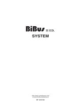
STRUCTURE
The calling module with directory consists of the following parts:
1 K-Steel 2 module front panel.
2 Alphanumeric display, two-rows, 16-characters, back-lit.
3 Yellow back-lit name selection buttons.
4 Green back-lit number pad buttons with yellow back-lit function
buttons: “Cancel”, “Key” and “Call”.
5 Additional alphanumeric keyboard (1038/73) connector.
6 Extractable connection terminal boards (MP2, MV1, MS1).
7 Calling module speaker volume adjustment trimmer.
8 Calling module microphone volume adjustment trimmer.
9 Programming alphanumeric keyboard (1032/65) connector
(CNP).
10 Programming button (for use only when password is not known).
11 LCD display contrast adjustment trimmer.
12 Extractable connection terminal board (MP1).
13 PC wire connector (CNS).
K-STEEL CALLING MODULE WITH REPERTORY Ref. 1072/14
PERFORMANCE - STRUCTURE
X
7
4
1
0
8
5
2
9
6
3
5
11
10
9
8
7
6
4
1
2
3
X
7
4
1
0
8
5
2
9
6
3
CNA
CNP
MP2 MV1 MS1
L2
L1
GND
SE2
SE1
~12 V
~0 V
GND
+T
H
DT
+EP
GND
P
PA
SP
SN
R
R1
13
12

sec.2b
−−−−
3
K-STEEL CALL MODULE
BIBUS 2
nd
Ed. VOP - Technical Manual
Ref. 1072/14
K-STEEL CALLING MODULE WITH REPERTORY
To restore default settings:
Disconnect module power.
Hold the red programming button pressed and power up the
module.
Hold the button pressed for approximately 10 seconds and wait
for a tone.
Release the button.
OPERATION
CALLS TO USERS
A user can be called by entering the user’s code on the keypad.
Obviously, the code must be known to do so. The name can be sought
in the integrated electronic directory if the code is not known.
CALLS TO USERS BY SELECTING THE NAME
The following message will appear on the display:
Press
or
to scroll the names and the codes. Hold either button
pressed to increase scrolling speed.
Select the name and press
to call the selected user.
The apartment door phone will ring for approximately 3 seconds. Hold
pressed to send up to three consecutive calls.
Name/code display example:
The following prompt will appear on the display if is not pressed for
longer than two seconds after selecting a name:
At this point, press
to call or press
or
to scroll the name list.
The following will appear on the display when the button
is
pressed:
Press to interrupt the call to the previously selected user.
The following message will appear on the display if the user picks up
the handset:
Press to end the conversation with the user.
The following message will appear if the user does not answer within
the programmed pick-up time:
•
•
•
•
DESCRIPTION OF TERMINALS AND
CONNECTORS
MP1 terminal board
~0 Power 12Vac
~12 Power 12Vac
+T Back-up power positive
GND Back-up power negative
SE1 Electrical lock connection
SE2 Electrical lock connection
MP2 terminal board
L1 Bus line 1st wire
L2 Bus line 2nd wire
GND Reference electrical ground
PA Hall door opener button input
SP Open door sensor contact input
MV1 terminal board
SN Video power unit on signal for video door phone systems
R Video switching enable signal for video door phone
systems
R1 Video power ground
MS1 terminal board
H Door opener code time band contact input
P Mail key input
GND Reference electrical ground
+EP Auxiliary device power
DT Not used
CNA Alphabetic keyboard connector 1038/73
CNP Programming keyboard connector 1032/65
CNS PC serial line connector
The module is programmed by default with a jumper between ground
and the “SP” signal to simulate the door closed contact. Remove the
jumper and connect the sensor between GND and SP when the open
door contact is required.
Connect the electrical lock positive to terminal SE1 and the negative
to terminal SE2 when polarised electrical locks are used.
IMPORTANT: Observe the instructions contained in section 1 for
wiring and maximum distances.
TECHNICAL SPECIFICATIONS
Power: 12Vac rated
Stand-by consumption: 300mAac max.
Maximum consumption: 600mAac max. (*)
R signal: Imax=80mA
Lock hold current: 190mA max.
Working temperature range: -10 +50°C
Humidity: 90% RH at 30°C
(*) With alphabetic keyboard 1038/73.
DEFAULT SETTINGS
Refer to section 1A “Programming” in this manual for how to
program the device.
The default settings of the device are:
System type: 2nd Edition
Station type: main
Code format: numeric (0001–9999)
Station number: 1
Pick-up time: 20s
Busy time: 20s
Door opener time: pulse
§
•
•
•
•
•
•
•
K-STEEL CALLING MODULE WITH REPERTORY Ref. 1072/14
DESCRIPTION OF TERMINALS AND CONNECTORS - TECHNICAL SPECIFICATIONS
DEFAULT SETTINGS - OPERATION
Select NAME
with ↑ or ↓
To call
press
URMET
1001
CALL
IN COURSE
TALK
PLEASE
User
does not reply

4
−−−−
sec.2b
K-STEEL CALL MODULE
BIBUS 2
nd
Ed. VOP - Technical Manual
Ref. 1072/14K-STEEL CALLING MODULE WITH REPERTORY
DOOR OPENER CODES
Press the button before entering each door opener code.
Symbol “∗” will appear on the display when entering the code for each
button.
The module will open the door if the code is valid. A warning will be
output if the code is not valid.
The sequence is the same for “Generic” and “Personal” door opener
codes: press followed by the door opener code. The following will
appear on the display:
The lock will be operated and the following message will appear if the
code is correct:
GENERIC DOOR OPENER CODES
The generic door opener codes can be used by residents and other
authorised persons to release the lock.
The calling module is dimensioned to contain up to eight generic
door opener codes for operating the electrical lock. The codes have
four digits (no letter permitted).
The eight generic door opener codes must be validated according
to the time of day. The codes will operate the door lock only if the
contact of the clock external to the module is open. Otherwise, the
eight generic codes cannot be used to open the lock.
PERSONAL DOOR OPENER CODES
A door opener code can be associated to each name. Other 250 door
opener codes can be thus programmed in addition to the generic
codes. These 250 door opener codes are not concerned by the clock
contact.
BUSY FUNCTION
This function is only required in systems with more than one calling
device. This function is used to ensure that a conversation lasts
sufciently long following a call. The following message indicates
busy status:
The keyboard is disabled during this time.
Two cases can occur:
BUSY TIME BEFORE THE CALL USER GOES ON-HOOK
This is the maximum time for the user to lift the handset or open the
door without loosing the call after the ring.
BUSY TIME AFTER USER GOES ON-HOOK
This is the minimum guaranteed conversation time from when the
handset is picked up.
CALLS TO USERS BY SELECTING THE CODE
Dial the code of the user to be called (numeric or alphanumeric with
optional keyboard). The following will appear on the display:
Enter the code and press the to call the selected user.
The apartment door phone will ring for approximately 3 seconds. Hold
pressed to send up to three consecutive calls.
Press to interrupt the call to the previously selected user.
The following message will appear on the display if the user picks up
the handset:
Press to end the conversation with the user.
The following message will appear if the user does not answer within
the programmed pick-up time:
DIRECT CALL TO CONCIERGE SWITCHBOARD
Press on a calling module installed in a system with concierge
switchboard to call it directly. This is only possible when the concierge
switchboard is in day mode, i.e. when the concierge service is
operative and the function has been activated (see “Programming”).
The following message will appear on the display:
The following will appear on the display if is pressed and either
the concierge switchboard is in night mode or the function has not be
activated (see “Programming”).
K-STEEL CALLING MODULE WITH REPERTORY Ref. 1072/14
OPERATION
CALL TO:
n°1001
CALL
IN COURSE
TALK
PLEASE
User
does not reply
Select NAME
with ↑ or ↓
CALL TO:
Switchboard
CODE NOT
VALID
LOCK REL. CODE
****
Go in
Please
LINE BUSY
Please wait

sec.2b
−−−−
5
K-STEEL CALL MODULE
BIBUS 2
nd
Ed. VOP - Technical Manual
Ref. 1072/14
K-STEEL CALLING MODULE WITH REPERTORY
ADJUSTMENTS
VOLUME ADJUSTMENT
Volumes are calibrated by default so not to require adjustments in
most cases.
Use a screwdriver to adjust the trimmers if required.
DISPLAY CONTRAST REGULATION
The display contrast is set at the factory and will not need to be
adjusted in most installations.
Use a screwdriver to adjust the trimmers if required.
K-STEEL CALLING MODULE WITH REPERTORY Ref. 1072/14
ADJUSTMENTS - ADDITIONAL ALPHABETIC KEYBOARD REF. 1038/73
INSTALLATION
ADDITIONAL ALPHABETIC KEYBOARD
Ref. 1038/73
The additional alphabetic keyboard Ref. 1038/73 can be used to
entered letters for dialling call codes.
The device must be combined with a calling module Ref. 1072/14 to
which it is connected by means of the specic connection wire. In any
case, the device must be arranged UNDERNEATH (or by THE SIDE
OF) the calling module.
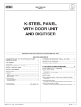
INSTALLATION
Calling module with repertory Ref. 1072/14 can be used alone or in
combination with a camera unit and/or alphabet keyboard add-on
Ref. 1038/73.
Examples of modular constructions using 2 or 3 module holder frames
with respective ush-mounting boxes are shown below.
The door unit module should be installed at a height of approximately
1.55 ÷ 1.60 metres.
Important
The module should not be illuminated from behind to make the calling
module display easier to read. Never direct the module towards
strong sources of light (e.g. the sun, lampposts, light bulbs, ashes
or glare).
FLUSH-MOUNTED VERSION
The ush-mounting box and respective frame must be used for ush-
mounted installation.
The available models, dimensions and box and frame installation
procedures are shown in Technical product manual - door phone and
video door phone systems - section “Modular Vandal-Proof Panel K-
Steel”.
1. Refer the protections from the hole to be used to pass the wires
only from the ush-mounting box.
X
G
D
A
J
H
E
B
I
F
C
h = 1,55 ÷ 1,60 m
X
7
4
1
0
8
5
2
9
6
3

6
−−−−
sec.2b
K-STEEL CALL MODULE
BIBUS 2
nd
Ed. VOP - Technical Manual
Ref. 1072/14K-STEEL CALLING MODULE WITH REPERTORY
6. Fasten the module holder frame to the ush mounting boxes by
means of the specic hinged attachment.
7. Fit the seal and close the frame.
K-STEEL CALLING MODULE WITH REPERTORY Ref. 1072/14
INSTALLATION
The holes in the upper part must only be used for introducing the
cables if overlapped to other boxes.
2. Flush the box and the required height considering the direction
and the indications provided for video systems.
Warning: During installation, protect all parts which will be
exposed to view from mortar, plaster and cement.
Never use abrasive detergents to clean units.
3. Fit the ush mounting box in line with the wall: it must not
project.
The wall surface on which the front rests must be as smooth as
possible (max. tolerance 1.5 mm).
4. If the internal production has been removed from the box for any
reason, insert it as shown in the gure. Fix it in the upper part not
used for xing the module holder frame.
IMPORTANT: the warranty conditions will be forfeited if the
protection is either not installed or installed incorrectly.
5. For tting, loosen the two tap screws and remove the crossbar
from the embedding box frame. Fit the modules in the frame.
§
§
max.
6 mm
n° 4 M4 x 16 mm
X
7
4
1
0
8
5
2
9
6
3
A
B
C
n° 7 M3

sec.2b
−−−−
7
K-STEEL CALL MODULE
BIBUS 2
nd
Ed. VOP - Technical Manual
Ref. 1072/14
K-STEEL CALLING MODULE WITH REPERTORY
WALL-MOUNTED VERSION WITH CASE AND
HOOD
Cases and hoods protect the calling module from the weather and
may be used for installation on walls without ush-mounted parts.
The case is provided with module holder frame.
The available models and the dimensions of cases and frames are
shown in Technical product manual - door phone and video door
phone systems section “Modular Vandal-proof panel K-Steel”.
8. Fasten the frame with the three screws provided.
The tool must only be used manually, and not tted on electrical
screwdrivers, to prevent damaging the screws and/or the tool.
K-STEEL CALLING MODULE WITH REPERTORY Ref. 1072/14
INSTALLATION
90°
OK
NO
X
7
4
1
0
8
5
2
9
6
3
1
1,55 m
2
n° 7 M3
3
4
5

8
−−−−
sec.2b
K-STEEL CALL MODULE
BIBUS 2
nd
Ed. VOP - Technical Manual
Ref. 1072/14K-STEEL CALLING MODULE WITH REPERTORY
K-STEEL CALLING MODULE WITH REPERTORY Ref. 1072/14
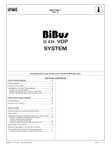
EXAMPLES OF MODULAR CONSTRUCTIONS
EXAMPLES OF MODULAR CONSTRUCTIONS
(*) A colour camera Ref. 1755/45 can be tted as an alternative.
S/N ......
S/N ......
1,55 - 1,60 m
Ref.
1072/14
Ref.
1072/14
Ref.
1755/30A
(∗)
Ref.
1755/30A
(∗)
Ref.
1755/30A
(∗)
Ref.
1755/30A
(∗)
Ref.
1038/73
Ref.
1038/73
Ref. 1155/62 Ref. 1155/61
Ref.
1072/14
Ref. 1155/62
S/N ......
Ref.
1072/14
Ref.
1072/14
Ref.
1038/73
Ref.
1038/73
Ref. 1155/61
S/N ......
Ref.
1072/14
Ref.
1072/14
S/N ......
Ref.
1038/73
Ref. 1155/63
Ref.
1072/14
Ref.
1072/14
X
7
4
1
0
8
5
2
9
6
3
X
7
4
1
0
8
5
2
9
6
3
X
7
4
1
0
8
5
2
9
6
3
X
G
D
A
J
H
E
B
I
F
C
X
G
D
A
J
H
E
B
I
F
C
X
7
4
1
0
8
5
2
9
6
3
Ref.
1038/73
Ref.
1072/14
X
G
D
A
J
H
E
B
I
F
C
X
7
4
1
0
8
5
2
9
6
3
Ref.
1155/62
Ref.
1155/63
Ref.
1755/30A
(∗)
Ref.
1755/30A
(∗)
/