Page is loading ...

sec.4c
−−−−
1
BIBUS 2
nd
Ed. VOP - Technical Manual
SECTION 4C
(REv.G)
CONCIERGE
SWITCHBOARD
PERFORMANCE ..............................................................................2
STRUCTURE ....................................................................................2
DESCRIPTION OF TERMINALS .......................................................3
TECHNICAL SPECIFICATIONS ........................................................3
WALL FITTING INSTALLATION ........................................................3
VIDEO MODULE SCAITEL INSTALLATION .....................................3
DESCRIPTION OF THE PARTS ........................................................3
Graphic display .............................................................................3
Keyboard ......................................................................................4
Ringer ........................................................................................... 4
TYPES OF USE ................................................................................4
Switchboard off ............................................................................4
Switchboard on ............................................................................ 4
Night service .................................................................................4
Day service ................................................................................... 4
OPERATING INSTRUCTIONS ..........................................................4
Switching on and off .....................................................................4
Day/night switchover ....................................................................5
Conversation service to and from internal stations ......................5
Storing calls ..................................................................................5
Stored call management ..............................................................6
Porter’s service .............................................................................6
Door opening functions ................................................................ 6
Audio line state indications during night service ..........................7
Special decoder management .....................................................7
Download from www.urmet.com Technical Manuals area.
SECTION CONTENTS
SPECIAL FUNCTIONS .....................................................................7
Adjusting date and time................................................................7
Keyboard lock ..............................................................................7
Other information on the display .................................................. 7
CONFIGURATION ............................................................................8
Programming steps ......................................................................8

SWITCHBOARD
Ref. 1072/42
2
−−−−
sec.4c
BIBUS 2
nd
Ed. VOP - Technical Manual
CONCIERGE SWITCHBOARD
SWITCHBOARD Ref. 1072/42
The door phone switchboard Ref. 1072/42 can exclusively be used in
Bibus II ed. systems for:
Communication from and to external stations with the possibility of
storing unanswered calls.
Day/Night porter’s lodge service (with or without the possibility of
intercepting calls from main stations directed to internal stations).
The switchboard Ref. 1072/42 is included in the SCAITEL range and
can be table or wall surface tted (see Installation chapter).
PERFORMANCE
Day/Night/Off service modalities.
User calls directly by entering number code or alphanumeric code
with letter prex or sufx from A to J.
User calls by selecting name stored in built-in repertory (max. 250
names).
Door phone call reception and storage (max. 50).
The switchboard can be programmed via built-in keyboard,
programming keyboard Ref. 1032/65 or PC.
Programmable door phone pick up time (10, 20, 30, 40s).
Programmable minimum conversation time (10, 20, 30, 40s).
Maximum conversation time: 250s.
Acoustic call made signal.
Busy function signalled by message on display.
Adjusting volume of speaker and handset.
Adjusting display contrast.
Switch-on signal management for video module in video door
phone systems.
Date/time function.
Multilingual message display without extra EEPROM.
Four special function keys (e.g. staircase lights).
Call tone level adjustment.
Recall signal management for controlling additional ringers.
Powered by Ref. 9000/230 (12Vca).
Messages in 15 languages: Italian, English, French, German,
Spanish, Portuguese, Swedish, Norwegian, Finnish, Dutch, Datch,
Slovak, Polish, Hungarian, and Russian.
•
•
•
•
•
•
•
•
•
•
•
•
•
•
•
•
•
•
•
•
•
•
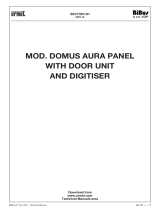
STRUCTURE
The switchboard consists of the following parts:
1 Switchboard casing.
2 Graphic display.
3 Multiple purpose keyboard.
4 Ringer volume adjuster.
5 Handset.
6 Handset part.
7 Table mounting stand.
8 Four holes for wall tting.
9 Two pairs of housings for brackets connecting to optional video
module Ref. 1732/1.
10 Boss connection wire.
11 Wire hole.
12 Casing cover catch.
13 Adhesive feet.
14 Support plate.
15 Connector protection ap.
16 Connector for printer or PC.
17 Connector for Programming terminal Ref. 1072/60.
18 Display contrast adjuster.
SHIFT
F1
4
F2
5
F3
6
J
O
A1 B2 C3
D4 E5 F6
G7 H8 I9
ON
OFF
MM M
1 2
220 mm
260 mm 69 mm
1234
5 6
714 8
88 12 11
8
9
13
9
10
13
15 17 1816
SWITCHBOARD Ref. 1072/42
PERFORMANCE - STRUCTURE

SWITCHBOARD
Ref. 1072/42
sec.4c
−−−−
3
BIBUS 2
nd
Ed. VOP - Technical Manual
CONCIERGE SWITCHBOARD
DESCRIPTION OF TERMINALS
The following terminals are provided on the wiring junction box:
~0 12Vac power
~12 12Vac power
L1 Bus Line 1st connector
L2 Bus Line 2nd connector
CV Video module control signal
RPCH Call repeat signal
GND Control signal earth
TECHNICAL SPECIFICATIONS
Power: 12vac nominal
Stand-by consumption: 140mAac max
Maximum consumption: 350mAac max
RPCH signal: Imax= 40mA
Operating temperature: -5 +45°C
Moisture: 90% RH at 30°C
WALL FITTING INSTALLATION
The switchboard is arranged at the factory to be table mounted. To t
the switchboard on the wall:
1) Remove the table stand (7) and the two feet (13).
2) Remove the catch (12) from the switchboard casing (1) with a
small screwdriver.
3) Remove the switchboard casing (1) from plate (14).
4) Open the handset part (6).
5) Fasten the base to the wall with the four bolts provided using the
holes (8).
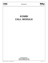
vIDEO MODULE SCAITEL INSTALLATION
The video module with bracket Ref. 1732/957 can be tted on the
right or on the left of the switchboard. Two brackets and four screws
are provided to be tted in the specic housings (9). Apply the
specic stand (38) and the two feet (39) provided on the video module
bracket.
DESCRIPTION OF THE PARTS
GRAPHIC DISPLAY
The switchboard features a back-lit graphic display with ve 10/20
character rows.
During operation, the available display characters are organised in the
following dedicated areas:
1) ee area (2 characters)
This area contains the main station code which is communicating
with the switchboard or standing-by.
2) iiii area (4 characters)
This area contains the code of the internal station called by the
main module.
3) f area (1 character)
This area contains a symbol indicating the type of voice connection.
Possible symbols are:
...
when the main station ee has called the internal station iiii and the
switchboard has intercepted the call but has not yet answered;
when the switchboard is communicating with main station ee;
when the switchboard is communicating with internal station iiii;
when main station ee is communicating with internal station iiii.
4)
area (1 character)
This area can contain a symbol indicating that internal station
iiii intercepted by the switchboard has not yet been called by the
switchboard operator. Internal station iiii will be called and the
symbol will disappear when the switchboard operator presses the
call button.
5) IIII area (4 characters)
This area contains the code of the internal station calling the
switchboard. The eld will be emptied and the code will be stored
if the switchboard operator does not take the call.
6) dddd area (4 characters)
This area contains the codes entered by the switchboard operator,
i.e. call codes, special codes, door opening call module codes.
Press button to clear the area. This area can also contain a
directory user’s code.
7) xxxxxxxxxxxxxxxx area (16 characters)
This area contains the name of the user concerned by a
communication.
8) dd/mm/yyyy HH:MM:ss area (20 characters)
Normally, this area contains the date and the time. This area is
temporarily used while scrolling the directory to display the user’s
name.
9) yyyyyyyyyyyyy area (13 characters)
This area, along with the nn rrrr area, is used to scroll the directory
and display the user’s name.
10) nn rrrr area (7 characters)
This area indicates the apartment station calls stored in the
switchboard:
nn is the number of calls;
rrrr is the code of the stored apartment station.
This area is also used to request conrmation before deleting
stored codes.
SWITCHBOARD Ref. 1072/42
DESCRIPTION OF TERMINALS - TECHNICAL SPECIFICATIONS - WALL FITTING INSTALLATION
vIDEO MODULE SCAITEL INSTALLATION - DESCRIPTION OF THE PARTS
eeiii
IIII dddd
xxxxxxxxxxxxxxxx
dd/mm/yyyy HH:MM:SS
yyyyyyyyyyyyynn rrrr
40
40
38
39
Bracket
Ref. 1732/957

SWITCHBOARD
Ref. 1072/42
4
−−−−
sec.4c
BIBUS 2
nd
Ed. VOP - Technical Manual
CONCIERGE SWITCHBOARD
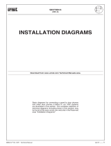
KEYBOARD
The keyboard features dual function numerical/alphabetical keys to
enter internal station call codes, door opening codes. Press
SHIFT
and the corresponding key to enter a letter. The keyboard also
features various function keys which are described in the following
paragraphs.
19 ON/OFF button with green LED.
20 DAY/NIGHT service switchover button with green LED.
21 Directory scrolling button Z...A
22 Internal station call button.
23 Directory scrolling button A…Z
24 Stored internal station code deletion button.
25 Stored user memory call button with red LED.
26 Stored user code scroll button.
27 Programmable function buttons.
28 SHIFT button to select the second button function.
29 Clock setting button.
30 Main door opening button.
31 Secondary door opening button.
32 Main station voice switch button.
33 Error correction button.
34 Button for though voice switching between main station and
internal station.
35 Button for voice switching towards internal station.
36 Button not used
37 Alphanumerical keyboard to dial call codes.
RINGER
The modulated electronic ringer volume can be adjusted to three
levels (MINIMUM-MEDIUM-MAXIMUM) by means of a lever (4) on the
front part of the handset (6).
TYPES OF USE
The way the switchboard works depends on how it was congured
when it was installed and its status. The switchboard can intercept
the calls from main stations only in ‘Day’ mode. Calls from apartment
stations will always be intercepted.
SWITCHBOARD OFF
When the switchboard is off, it behaves as if it were not present in
the system. Calls from main stations are directly sent to the internal
stations. Calls from internal stations are lost.
SWITCHBOARD ON
The switchboard can be switched on to operate in DAY service mode
or NIGHT service mode.
NIGHT SERvICE
In this condition, the porter’s service is inhibited and the calls from
main stations are directly sent to the internal stations. The switchboard
can call any internal station. Any calls to internal stations are normally
received by the switchboard. If required, the operator can deal with
them. If not, the calls will be stored.
DAY SERvICE
In this condition, the switchboard implements the concierge function
by intercepting the calls from main stations to apartment stations.
The switchboard can call any apartment station. Calls from apartment
stations are normally received by the switchboard. If required, the
operator can deal with them. If not, the calls will be stored.
OPERATING INSTRUCTIONS
SWITCHING ON AND OFF
CASE 1: SWITCHBOARD WITHOUT PASSWORD.
Press the
ON
OFF
button. The following message will appear on the display
for three seconds:
The software version number is shown in the top row. After three
seconds the switchboard will start working according to the mode
used when it was switched off. LED will light up if the switchboard
is in DAY mode. If the switchboard is in NIGHT mode, LED will not
come on. In any case, the following message will appear when the
switchboard is standing by:
The switchboard display is back-lit with a LED presenting a 30”
timeout. The light will come on when the handset is lifted, any key is
pressed or when a call or alarm is received.
Hold the
SHIFT
button pressed while pressing the
ON
OFF
button to
switch the switchboard off.
The message “TO BE CONFIGURED” will appear on the display
instead of the “SYSTEM OK” message if the switchboard has
not been congured.
CASE 2: SWITCHBOARD WITH PASSWORD
Press the
ON
OFF
button. The following message will appear on the display
for three seconds:
The software version number is shown in the top row. Enter the
password programmed by the installer (a sequence of asterisks will
appear in the last row) and press the call button . The switchboard
§
25/05/2000 08:10:54
SWITCHBOARD Ref. 1072/42
TYPES OF USE - OPERATING INSTRUCTIONS
REL.1.0
SYSTEM OK
STARTING password
1 2
SHIFT
F1
4
F2
5
F3
6
JO
A1 B2 C3
D4 E5 F6
G7 H8 I9
ON
OFF
MM M
36
35
34
32
30
28
33
31
29
37
19
20
21
23
25
27
22
24
26

SWITCHBOARD
Ref. 1072/42
sec.4c
−−−−
5
BIBUS 2
nd
Ed. VOP - Technical Manual
CONCIERGE SWITCHBOARD
will start working according to the mode used when it was switched
off. The switchboard will be switched off if either the password is
wrong or after one minutes from pressing the
ON
OFF
button.
If the switchboard is in DAY mode, LED will come on.
If the switchboard is in NIGHT mode, LED will not come on. In
any case, the following message will appear when the switchboard
is standing by:
The switchboard display is back-lit with a LED presenting a 30”
timeout. The light will come on when the handset is lifted, any key is
pressed or when a call or alarm is received.
Hold the
SHIFT
button pressed while pressing the
ON
OFF
button to
switch the switchboard off.
The message “TO BE CONFIGURED” will appear on the display
instead of the “SYSTEM OK” message if the switchboard has
not been congured.
DAY/NIGHT SWITCHOvER
Press
SHIFT
- to switch from DAY to NIGHT. The switchboard will
switch its service status.
CONvERSATION SERvICE TO AND FROM INTERNAL
STATIONS
The switchboard can call and be called by internal stations with this
service.
CALLS TO INTERNAL STATIONS
To call an internal station, lift the handset, dial the internal station
code with the number pad (37) and press the call button . If you
make a mistake, correct the entered data with the delete button
. Hold
SHIFT
pressed and press the respective key to enter a letter.
For example, to call a user whose code is “C126”, enter the following
key sequence ”
SHIFT
-3”, ”1”, ”2”, ”6” and then press button . The
entered code will appear in the second row. For example:
When the call is forwarded, the information displayed on the second
line will disappear and the called person’s name will appear (if present
in the directory).
The call will be forwarded only when the handset is off-hook.
If the user’s code is not known, the user can be selected using the
directory scrolling buttons and . The name will appear on the
third line of the display and the code on the second line.
CALLS FROM APARTMENT STATIONS
The calls from apartment stations will be managed by the switchboard
regardless of the service status (day/night). The device will store the
user code if the operator does not lift the handset before timeout
selected by the user.
When a call is received, the ringer will be operated for approximately
1 second and, at the same time, the apartment station code will
§
§
appear on the display along with the name of the caller as shown in
the following example:
Lift the handset within the pick up time. The switchboard can
communicate with the internal station and the following will appear
on the display:
To indicate that the switchboard is communicating with the internal
station 1634. At the end of the conversation, the information will
disappear from the display.
STORING CALLS
After receiving a call from an apartment station, the calling apartment
station code will be automatically stored by the switchboard if the
operator does not lift the handset before the timeout. The internal
memory dedicated to storing internal station call codes will not be
cleared if the switchboard is powered down. The switchboard can
store up to 50 internal station call codes.
Three buttons on the keyboard are exclusively dedicated to managing
booked calls (buttons
M
,
M
,
M
).
The stored call code and the total number of stored calls (from “1”
to “49”) are displayed on the bottom row as shown in the following
example:
In this case, the display shows that there are ten stored calls and that
the rst call was made by user “5748”. Calls from internal stations are
stored regardless of the switchboard mode (DAY/NIGHT) unless this
function was disabled when the switchboard was programmed. The
booking memory status is indicated by LED
M
. The LED will light
up if there are one or more calls stored. When the memory is full,
i.e. when 50 calls have been received, you should clear the booking
memory with the specic buttons (call or delete) because only up to
fty calls can be stored.
STORED CALL MANAGEMENT
vIEWING STORED CODES AND NAMES
The booking codes and names can be displayed by pressing the
specic scroll button
M
. For example, the following will appear if
calls were booked by users 1234 and A100:
SWITCHBOARD Ref. 1072/42
OPERATING INSTRUCTIONS
25/05/2000 08:10:54
C126
25/05/2000 08:10:00
1634
MARIO ROSSI
25/05/2000 08:10:00
1634
25/05/2000 08:10:00
25/05/2000 08:10:00
10 5748
MARIO ROSSI
25/05/2000 08:10:00
02 1234

SWITCHBOARD
Ref. 1072/42
6
−−−−
sec.4c
BIBUS 2
nd
Ed. VOP - Technical Manual
CONCIERGE SWITCHBOARD
opened when the handset is lifted:
The operator can speak to the caller and if required call internal
station 1234 or another station. The “bell” symbol indicates that
the switchboard can directly call code 1234 simply by pressing call
button without entering the code 1234. The following will appear
on the display:
When the called user answers, press button to put the main station
directly in communication with the internal station. The following will
appear on the display:
At the end of the conversation (when the internal station handset is
hang up), the information will disappear from the display.
When the switchboard enabled for the porter’s service is managing
a call between the main station and the internal station it can switch
to the main station at any time by pressing button and put the
internal station on hold. Alternatively, button can be pressed to
switch to the internal station and put the main station on hold.
DOOR OPENING FUNCTIONS
Any door can be opened from the switchboard (associated to a main or
secondary station) in any moment. This function is called “PRIORITY
DOOR OPENING”.
OPENING THE MAIN DOOR
Two conditions can occur:
Following a main station call: when the switchboard establishes
a communication with a main station or is managing the
communication between the apartment station and outside, simply
press the main door opening button .
In any other moment: enter the main station code (1-12) followed
by the main door opening button .
OPENING A SECONDARY DOOR
Enter the secondary door code (0-9) and press the secondary door
opening button .
AUDIO LINE STATE INDICATIONS DURING NIGHT
SERvICE
The state of the audio line is always shown on the switchboard display.
The state is that of the main unit and couplers; it is not possible to
see whether secondary units and decoders are engaged. The audio
channel state can be:
Free: no communication is in progress. Nothing is shown in the
•
•
•
Press button
M
once. The following will appear:
Press the button
M
again to return to the original display (1234).
After selecting the code as described above, the operator can either
call the selected internal station or delete the booking.
CALLING THE SELECTED INTERNAL STATION
Press the stored call button
M
.
The call will be forwarded only if the handset is lifted.
DELETING A STORED CALL
The operator can delete a stored call to clear all the calls (LED
M
off).
For example, to delete call code A100:
The following message will appear on the display after pressing
button
M
:
Press button
M
again within three seconds to delete. If the button is
not pressed the entire operation is ignored.
Deletion will be automatic if the switchboard calls the booked
user and the user picks up.
PORTER’S SERvICE
When the switchboard is in Day mode it is enabled to intercept calls
from main stations to the apartment stations, in addition to calling and
being called by apartment stations. When a call is received from the
main station, the tone will be different from that used for calls from
apartments stations. Furthermore, the calling code (from 001 to 012)
and the code entered by the user (from 0000 to 9999) will appear on
the display. For example, the following will appear if main station 010
calls user 1234 and the switchboard intercepts the call:
The video module will come on if the switchboard is connected to
one. The voice line to the main calling station will automatically be
§
§
10 1234
25/05/2000 08:10:00
SWITCHBOARD Ref. 1072/42
OPERATING INSTRUCTIONS
10...1234
25/05/2000 08:10:00
PAOLO BIANCHI
25/05/2000 08:10:00
02 A100
25/05/2000 08:10:00
OK
10 1234
25/05/2000 08:10:00
PAOLO BIANCHI
25/05/2000 08:10:00
02 A100
25/05/2000 08:10:00

SWITCHBOARD
Ref. 1072/42
sec.4c
−−−−
7
BIBUS 2
nd
Ed. VOP - Technical Manual
CONCIERGE SWITCHBOARD
respective row of the display.
Busy: a communication is in progress on the voice channel and it
cannot be interrupted since the busy timeout has not passed. The
message “BUSY” will appear in the respective row of the display.
Engaged: a communication is in progress on the voice channel and
it can be interrupted since it is lasting for a time exceeding the busy
timeout. The symbol will appear in the respective row of the
display.
If the channel is busy or engaged, the switchboard operator cannot tell
which devices are involved in the communication. Furthermore, if the
channel is busy, the communication between the two devices cannot
be interrupted while the call can be interrupted by the switchboard
operator if the channel is engaged.
Example: a main station calls an internal station:
If the call lasts for longer than the busy timeout:
SPECIAL DECODER MANAGEMENT
The switchboard is enabled to manage electrical actuators using for
the purpose special service decoders Ref. 1072/80. The switchboard
has 6 function buttons of which only the rst 4 are used (F1, F2, F3, F4)
for implementing appropriately congured special decoder functions.
The following appears when the button is pressed.
SPECIAL FUNCTIONS
ADJUSTING DATE AND TIME
Press the
SHIFT
- buttons at the same time to set/adjust the
date and the time. The following will appear on the display:
The rst row indicates the date format, the digits corresponding to the
day, month and year can be entered in the second row. Press the call
button to conrm. Enter the day, month and year to change the
date and press the call button .
•
•
The time can now be entered:
Enter the hours and the minutes and conrm by pressing the call
button .
After conrming the time, the message “WAIT” will appear on
the switchboard for approximately three seconds after which the
switchboard will return to its normal service.
KEYBOARD LOCK
The keyboard can be locked if the switchboard operator needs to
leave the service to prevent carrying out action with the keyboard.
To do this, press
SHIFT
and the main door opening button at the
same time. No commands from the keyboard will be accepted by
the switchboard when the keyboard is locked, including DAY/NIGHT
service switchboard. The message “XXXX” will appear in the user
code entry eld. Press the same keys to release the keyboard lock.
Without the password, the switchboard will remain locked also if
it is powered down and then re-powered.
OTHER INFORMATION ON THE DISPLAY
Calling an internal station which does not exist in the system. The
following will appear on the display:
Data line not connected or short-circuited:
The warning will appear until the error is solved.
§
SWITCHBOARD Ref. 1072/42
SPECIAL FUNCTIONS
BUSY
25/05/2000 08:10:00
DD/MM/YY
--/--/--
25/05/2000 08:10:00
OPERATION OK
25/05/2000 08:10:00
HH/MM
--/--
25/05/2000 08:10:00
WRONG CODE
25/05/2000 08:10:00
DATA LINE ERROR
25/05/2000 08:10:00
23/05/2000 08:10:00

SWITCHBOARD
Ref. 1072/42
8
−−−−
sec.4c
BIBUS 2
nd
Ed. VOP - Technical Manual
CONCIERGE SWITCHBOARD
CONFIGURATION
The conguration cycle can be activated:
1) With the switchboard powered and the handset on-hook, hold
the
SHIFT
button pressed, press button repeatedly until the
language conguration step appears on the display. Press button
for 3s to quit conguration mode.
2) With the programming adapter 1072/60 inserted in the connector
(17).
3) By connecting to a PC via connector (16).
The switchboard can be programmed and congured rapidly by means
of a personal computer suitably connected to the switchboard serial
port. Use B-BUS PC program to make switchboard programming
easier and faster. The B-BUS program (version 2.0 or higher) can be
downloaded from the URMET web site (http://www.urmetdomus.
com) free of discharge.
Minimum PC requirements are:
486 processor or above.
Windows 95 or 98 operating system.
Use of a mouse is recommended.
A cable with the following connections (not provided) is required:
PROGRAMMING STEPS
The programming steps are shown on the switchboard for conguring
via switchboard or programming adapter module 1072/60. Use
buttons and to go to the previous/next menu. Press button
to access the various switchboard programming steps.
The programming buttons refer to conguration via the
switchboard. Refer to the following table for the programming
adapter buttons:
•
•
•
§
STEP 1 - LANGUAGE
The following menu will appear on the switchboard:
Press buttons and to scroll the various languages. Press
to
select the required language.
STEP 2 - PICK UP TIME
The following will appear on the switchboard:
To change the parameter, simply press buttons 1-4 and press button
.
PICK UP TIME
The pick up time is the maximum time within which the user must
answer the door phone. The system is busy during this time. All
devices in the system must have the same pick up time.
If the switchboard call comes from an apartment station, the
calling stations will not be busy during the pick-up time.
STEP 3 - BUSY TIME
The following will appear on the switchboard:
Use 1-4 buttons to select and button to conrm.
BUSY TIME (MINIMUM CONvERSATION TIME)
When a user is called by the switchboard and answers the door
phone, or when the switchboard answers a door phone call, the call
stations will be busy for the minimum programmed conversation
time. A communication that has just started cannot be interrupted.
All devices in the system must have the same minimum conversation
time (busy time).
If a call is made from the door unit during a conversation between
user and switchboard, at the end of the minimum conversation
time the line will be freed and the switchboard may communicate
with the door unit. If instead, during a conversation between the
door unit and the switchboard a user makes a call, this event will
be stored by the switchboard. The switchboard operator will call
the user back.
§
§
SWITCHBOARD Ref. 1072/42
CONFIGURATION
DB9 FEMALE DB9 FEMALE
SWITCHBOARD 1072/42
P1
RS232 PC
P1
2
1
4
5
3
7
6
9
8
2
1
4
5
3
7
6
9
8
Function Local
External
keyboard keyboard
programming programming
Select menu and
buttons ← and → buttons
OK (Enter)
button ↵ button
Escape Hold
button
button
(return to upper menu) pressed for 3s
Blank Press characters SP button
Backspace Press characters BS button
(for correcting)
Select special Press characters / button
characters
Delete an
button BS button
associated code
booking
STEP 1
ENGLISH
STEP 2
20
Pick up time
(10,20,30,40 0)
STEP 3
20
Busy time
(10,20,30,40 0)

SWITCHBOARD
Ref. 1072/42
sec.4c
−−−−
9
BIBUS 2
nd
Ed. VOP - Technical Manual
CONCIERGE SWITCHBOARD
STEP 4 - CODE TYPE
The following will appear on the switchboard:
Use 1-3 buttons to select and button to conrm.
CODE TYPE
The switchboard can be used to call users with either a numeric code
(0001-9999), an alphanumeric code and letter prex (x000-x999) or
an alphanumeric code with letter sufx (000x-999x). Letters from
A to J.
STEP 5 - CALL REPEAT
The following will appear on the switchboard:
To change the parameter, simply press buttons 0-3 and press button
.
Set 0: the terminal is never active; set 1: the terminal is active during
rings for external calls; set 2: the terminal is active during rings for
internal calls; set 3: the terminal is active during all rings.
STEP 6 - PASSWORD PROGRAMMING
The following will appear on the switchboard:
To change the password, simply enter six numbers and press button
.
The system will ask for the password every time the switchboard is
switched on with the
ON
OFF
button.
The password is only numeral.
STEP 7 - ENTER CODES AND NAMES
The following will appear on the switchboard:
Enter the code and press to conrm.
Enter the name using buttons and and press to conrm.
Press the key or key to quit the menu.
The message “CODE ALREADY EXISTS” will appear if an existing
user code is inserted. Conrmation is required to proceed.
§
§
STEP 8 - EDIT CODES AND NAMES
The following will appear on the switchboard:
Press buttons and
to scroll the names.
Press button to access code editing mode.
Press button again to access name editing mode.
Press the key to quit the menu.
If a code is changed you will be asked to conrm. Press key to
conrm the operation; press the key to cancel the operation.
To change the name as well, repeat the edit sequence.
STEP 9 - DELETE CODES AND NAMES
The following will appear on the switchboard:
Key conrms the operation. The key cancels the operation.
STEP 10 - ASSOCIATING CODES TO DOOR PHONES
The following will appear on the switchboard:
Press buttons and to scroll the names.
Press : a symbol (triangle) will appear next to the name to conrm
the association:
Up to three extensions can be associated to each code.
Press button to remove the triangle symbols.
Hold pressed for 3 seconds to establish the association.
The switchboard will quit programming mode at the end of the
association.
§
•
•
§
•
•
SWITCHBOARD Ref. 1072/42
CONFIGURATION
STEP 5
0
CALL REPEAT
1=NUM 2=PREF 3=SUF
STEP 6
STARTING PASSWORD
STEP 7
CODE:
NAME:
STEP 8
CODE:1234_
NAME:
ROSSI
STEP 9
ERASE ALL
OK
STEP 10
CODE:1234
NAME:
ROSSI
STEP 10
CODE:1234
NAME:
ROSSI
STEP 10
DOOR PHONE PROG.
1234
STEP 4
1
Code type
1=NUM 2=PREF 3=SUF

10
−−−−
sec.4c
BIBUS 2
nd
Ed. VOP - Technical Manual
/