Page is loading ...

sec.5
−−−−
1
BIBUS 2
nd
Ed. VOP - Technical Manual
SECTION 5
(REV. H)
COUPLERS
POWER UNITS
VARIOUS DEVICES
BUS COUPLER WITH TRANSFORMER Ref. 1072/24 2
VIDEO VOP POWER UNIT Ref. 1074/20 3
EXTENDED DIFFERENTIAL VIDEO SIGNAL
REGENERATOR Ref. 1795/250 4
SECURITY TRANSFORMER Ref. 9000/230 5
ADDITIONAL POWER SUPPLY Ref. 789/2 5
SUPPLEMENTARY POWER UNIT 12Vdc - 15Vdc Ref. 1090/850 6
VOP VIDEO DISTRIBUTOR Ref. 1795/40 7
VOP FLOOR VIDEO DISTRIBUTOR Ref. 1074/54 7
PROGRAMMING KEYBOARD Ref. 1032/65 8
PROGRAMMING ADAPTER Ref. 1072/60 8
CABLE FOR PROGRAMMING DIRECTORIES
FROM THE PC Ref. 1072/57 9
PROGRAMMING KIT BIBUS 2ND EDITION Ref. 1072/58 9
Download from www.urmet.com Technical Manuals area.
SECTION CONTENTS
CALL REPEATER AUXILIARY RELAY Ref. 788/22 10
SUPPLEMENTARY RELAY Ref. 788/52 11
SPECIAL DECODER Ref. 1072/80 11
BIBUS PABX INTERFACE Ref. 1072/67 14
POWER LINE PROTECTION DEVICE 230Vac 4000VA
Ref. 1332/85 16
POWER LINE FILTER 230Vac 4000VA Ref. 1332/86 17
POWER LINE PROTECTION DEVICE Ref. 1332/80 17
MULTIPOLAR WIRE FOR VOP SYSTEMS Ref. 1074/90 18
SUPPLEMENTARY THREE-TONE RINGING FOR BIBUS
Ref. 1072/59 19
WIRELESS CALL REPEATER Ref. 4311/13 20
VOP 4-USER AUDIO VIDEO DISTRIBUTOR Ref. 1074/55 21

2
−−−−
sec.5
COUPLERS - POWER UNITS - VARIOUS DEVICES
BIBUS 2
nd
Ed. VOP - Technical Manual
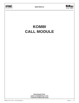
BUS COUPLER WITH TRANSFORMER
Ref. 1072/24
V
D E
PERFORMANCE
Powers the two-wire bus on main push-button panel side: up to 12
stations + 1 switchboard.
The bus on door phone side is called the “column” and is split into
two spines. The two spines are reciprocally equivalent and can be
separately cut off in the case of a failure. This event is indicated by
the two LEDs corresponding to the spines.
Powers the column (two spines and two wires): max. 50 door
phones + 1 secondary push-button panel. Up to 30 door phones +
1 secondary push-button panel can be connected if open door LED
feature is provided. In this case, an additional coupler cannot be
used to increase the number of door phones in the column if this is
connected to a secondary call station.
Repeats the data between the two buses.
Provides bus line impedance on main push-button panel side and
door phone side to allow audio modulation.
Provides the current needed to generate the door phone call and
the oor call.
Couples the voice of the two buses.
Powers electrical door lock and name tag lights.
Equipped with low voltage relay for controlling “staircase lights”.
Equipped with VOP video power unit controller (1074/20).
DESCRIPTION OF TERMINALS,
CONFIGURATIONS AND DISPLAYS
B1 Spine 1 working LED.
B2 Spine 2 working LED.
M/S Master/Slave conguration plug connector
L1, L2 Connection to bus on main push-button panel side
B1A, B1B Connection to column spine 1
B2A, B2B Connection to column spine 2
0, ~230 Mains.
~0, ~12 Can power the following alternatively:
• 1 calling module;
• 1 concierge switchboard;
• 1 electrical door lock (see technical specications);
• bulb or name tag lighting LED
(see technical specications).
C, NA, NC “Staircase lights” relay exchange.
CM, GND 1074/20 controller.
•
•
•
•
•
•
•
•
•
•
TECHNICAL SPECIFICATIONS
Power supply: 230Vac ± 10% 50Hz
Power: 37VA
L1, L2: 22Vdc 120mA
B1A, B1B: 22Vdc 60mA
B2A, B2B: 22Vdc 60mA
~0, ~12: 12Vac 1.1A
Relay contacts: 24Vdc 1.2 A - 24Vac 1.2A
Protections: PTC
(1)
Temperature: -5°C +40°C
(1)
Disconnect the mains power for at least 60 seconds to reset the
power unit if the PTC trips due to overload or short-circuit.
INSTALLATION AND CONFIGURATION
Install the coupler in a dry place. Keep slots open to prevent overheating
the device. Do not install the coupler near devices generating strong
magnetic elds.
The device can be tted on a DIN EN 43870 bar (12 modules).
The coupler is congured as a slave by default.
Insert the specic plug provided to congure the coupler as a master.
Only one coupler can be congured as a master in each system. All
other coupling devices must be congured as a slave.
Each coupler can be connected to up to 50 door phones (including
door phones in parallel) in two spines.
Organisation in spines is useful because if a spine fails (spine bus
short-circuit or faulty door phone), it can be cut off from the system
permitting the remaining spines to work normally.
STAIRCASE LIGHT CONTROLLER RELAY
The coupler is equipped with a low voltage contact controlled for one
second subsequent to the following events:
Pressing of “staircase lights” button on any door phone connected
to the respective spines.
Pressing of “staircase lights” button on secondary door unit
connected to the respective spines.
Pressing of “staircase lights” button on any main door unit (with
digitiser only).
Pressing on concierge switchboard button F1.
TROUBLESHOOTING
The bus coupler has two LEDs indicating the status of the respective
door phone spine. One or more coupler LEDs will go out to indicate a
short-circuit on the corresponding door phone spine.
•
•
•
•
BUS COUPLER WITH TRANSFORMER Ref. 1072/24
PERFORMANCE - DESCRIPTION OF TERMINALS, CONFIGURATIONS AND DISPLAYS -
TECHNICAL SPECIFICATIONS - INSTALLATION AND CONFIGURATION - TROUBLESHOOTING
90 mm
75 mm
216 mm
(12 DIN modules)
"Master" configuration
"Slave" configuration
BUS COUPLER WITH TRANSFORMER Ref. 1072/24

sec.5
−−−−
3
COUPLERS - POWER UNITS - VARIOUS DEVICES
BIBUS 2
nd
Ed. VOP - Technical Manual
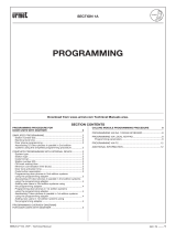
VIDEO VOP POWER UNIT Ref. 1074/20
The video VOP power unit is provided complete with a modulator.
The device takes a differential video signal from the camera and
outputs the VOP signal (power + video signal).
The main characteristics of this power unit are:
Two differential video inputs for signal reception from primary and
secondary cameras.
Video signal switching of two inputs via internal relay.
VOP column power output consisting of overlapped power and one
differential video signal.
Output to power a camera, a video signal converter and a relay
box.
Arrangement for connecting bus coupler Ref. 1072/24.
Possibility of equalising video signal from main station by setting
distance (via dip switch).
Possibility of connecting up to 50 video door phones in in/out mode
(*).
Possibility of connecting up to 13 oor distributors (*).
Maximum distance between power unit and last monitor: 200m (*).
Maximum distance between power unit and main camera: 400m.
Maximum distance between power unit and secondary camera:
200m.
(*) Conguration with maximum number of devices at maximum
distance may be obtained with Atlantico video door phones only;
see indications in section 1 for other congurations.
TERMINALS DESCRIPTIONS
VP
}
VOP column power terminals
VP
R2 Camera power positive
R1 Camera power negative
CM Modulator command from Ref. 1072/24
GND Modulator command negative from Ref. 1072/24
M Remote modulator command
R Video switching enable signal (from main to secondary)
R1 Video ground
A Main video signal
B Main video signal
AS Secondary video signal
BS Secondary video signal
TECHNICAL SPECIFICATIONS
Power supply: 230Vac ± 10% 50Hz
Power: 45W
R2, R1 output: 18Vdc ± 10% 200mA
VP output: 28Vdc ± 5% @700mA intermittent
(4 minutes on - 4 minutes off)
Temperature: 10°C / +40°C
•
•
•
•
•
•
•
•
•
•
•
INSTALLATION AND CONFIGURATION
The casing is suitable for tting on DIN bar and wall by means of
screws and bolts; in all cases, the power unit must be installed in
a dry place where it is sheltered from the elements, respecting the
safety standards.
The distance of the main camera must be set on the VOP video power
unit for the video signal to be correctly regenerated inside the video
power unit before being transmitted to the column.
Set the distance of the camera closest to the power unit in systems
with several cameras.
A signal regenerator Ref. 1795/250 must be installed for cameras at
further distances.
IMPORTANT:
Observe the instructions contained in section 1 for wiring and
maximum distances.
VIDEO VOP POWER UNIT Ref. 1074/20
TERMINALS DESCRIPTIONS - TECHNICAL SPECIFICATIONS -
INSTALLATION AND CONFIGURATION
1
2
3
4
1
2
3
4
AB
0-200m
AB
200-400m
75 mm
180 mm
(10 DIN modules)
90 mm
96
mm
1 2 3 4
Distance
0 ÷ 200 mt
(default)
VOP power unit dip-switch
200 ÷ 400 mt
1 2 3 4
VIDEO VOP POWER UNIT Ref. 1074/20

4
−−−−
sec.5
COUPLERS - POWER UNITS - VARIOUS DEVICES
BIBUS 2
nd
Ed. VOP - Technical Manual
EXTENDED DIFFERENTIAL VIDEO SIGNAL
REGENERATOR Ref. 1795/250
The video signal regenerator Ref. 1795/250 must be used in extended
differential video systems (VDE) or Video Over Power (VOP) systems
in the event of insufcient video compensation regulation on the VDE
brackets or VOP power unit.
The regenerator receives signals Ai and Bi (differential video input) to
be compensated and outputs signals Ao and Bo (differential video
output) which are compensated and adapted to the distance of the
wires leading to the brackets.
Use dip-switches 1 - 2 - 3 as shown below to adjust video compensation
according to distance.
Ignore dip-switch 4.
TECHNICAL SPECIFICATIONS
Power: 18Vdc
Uptake: 180mA max
§
INSTALLATION
The device may be fastened to the wall by means of the bracket
provided or tted on a DIN bar.
Lever as shown in the gure to access the connection terminals.
WIRING DIAGRAM
EXTENDED DIFFERENTIAL VIDEO SIGNAL REGENERATOR
Ref. 1795/250
TECHNICAL SPECIFICATIONS - INSTALLATION - WIRING DIAGRAM
1
0
-
200
m
2
3
1
200
-
450
m
2
3
1
450
-
700
m
2
3
1
700
-
1
0
0
0
m
2
3
S
c
h
.
1
7
9
5
/2
5
0
IN
OUT
90 mm
103 mm
36 mm
(2 DI
N
modules)
1
0 -
200 m
2
3
1
200 -
450 m
2
3
1
450 -
700 m
2
3
1
700 -
1000 m
2
3
1
0 -
200 m
2
3
1
200 -
450 m
2
3
Sch. 1795/250
IN
OUT
1 2 3 4
Distance
between
TV CAMERA
1 and VOP
power unit
Distance
between
TV CAMERA 2
and VOP
power unit
Distance set
on VOP
power unit
Distance set
on signal
regenerator
≤ 200 m ≤ 200 m 0 ÷ 200 m* Not required
≤ 200 m 200 ÷ 400 m 0 ÷ 200 m* 200 ÷ 450 m
200 ÷ 400 m 200 ÷ 400 m 200 ÷ 400 m Not required
* Default settings.
A
B
R2
R1
Ai
Bi
R2
R1
Ref. 1795/250
IN
Ao
Bo
R2
R1
OUT
From
camera unit
To riser
column
(relay box
or VOP
power unit)
1072/24 788/52
TV
CAMERA
2
column
200 ÷ 400 m
≤ 200m
1795/250
TV
CAMERA
1
1
2
3
4
1074/20
1
2
3
4
1
2
3
4
dip-switch
1
2
3
4
dip-switch
EXTENDED DIFFERENTIAL VIDEO SIGNAL REGENERATOR Ref. 1795/250

sec.5
−−−−
5
COUPLERS - POWER UNITS - VARIOUS DEVICES
BIBUS 2
nd
Ed. VOP - Technical Manual
ADDITIONAL POWER SUPPLY Ref. 789/2
The power unit Ref. 789/2 is required to power the main camera
and the video signal Ref. 1795/40 distributor in systems with several
column.
TECHNICAL SPECIFICATIONS
Power supply: 230Vac ± 10% 50/60Hz
Power: 28VA
Outputs: R2 out 0.65A int.
RL 0.02A
V2 0.02A
Protection: with PTC thermal cutout (*)
Operating temperature: -5°C ÷ +45°C
Dissipated power after 1 average working hour: 4,2W
(*) If the PTC thermal cutout is tripped due to overload, cut off mains
voltage for at least 60” to reset the power supply unit.
STYLING AND DIMENSIONS
The power supply can be installed on a DIN bar or wall surface
mounted using 2 screws and plugs.
Connections are made by means of screw type terminal blocks.
The terminal blocks can accept conductors with a maximum cross-
section of 1.5mm
2
.
SECURITY TRANSFORMER Ref. 9000/230
V
D E
URMET Ref. 9000/230 transformer is used to power Bibus 2nd Edition
locks in systems tting traditional push-button panels and door units
with digitiser. Suitable for DIN bar tting, the device was designed and
made in compliance with the laws in force concerning isolation and
safety transformers being protected from direct and indirect contact
as required by the electrical system standards in force.
It carries IMQ marking and respective certications.
The transformer can be used to power up to 5 bulbs per push-button
panel.
TECHNICAL SPECIFICATIONS
Power supply: 230Vac, 50/60Hz
Power: 18VA
Secondary: 12 Vac
Peak load: 1.1A
Protections: with PTC
Dissipated power after 1 average working hour: 1.8W
Disconnect for 60” to reset after a short-circuit.
SECURITY TRANSFORMER
Ref. 9000/230
TECHNICAL SPECIFICATIONS
ADDITIONAL POWER SUPPLY Ref. 789/2
TECHNICAL SPECIFICATIONS - STYLING AND DIMENSIONS
PRI
S
c
h
.
9
0
0
0
/2
3
0
Sch. 9000/230
58 mm
54 mm
83 mm
(3 DIN modules)
Sch. 789/2
75 mm
126 mm
(7 DIN modules)
90 mm
96 mm
SECURITY TRANSFORMER
ADDITIONAL POWER SUPPLY
Ref. 9000/230
Ref. 789/2

6
−−−−
sec.5
COUPLERS - POWER UNITS - VARIOUS DEVICES
BIBUS 2
nd
Ed. VOP - Technical Manual
SUPPLEMENTARY POWER UNIT 12Vdc - 15Vdc
Ref. 1090/850
The Ref. 1090/850 power unit supplies voltage at 12Vdc or 15Vdc.
Remove the jumper between terminals P1 and P2 to obtain 15 Vdc
voltage output. The output voltage will be 12Vdc if the jumper is not
removed.
TECHNICAL SPECIFICATIONS
Power supply: 230Vac ±10% 50/60Hz
Power: 5VA nominal
Uptake: max 30mA
Outputs: Vout= 12Vdc 0,18A
(with jumper P1 - P2) default
Vout= 15Vdc 0,18A
(without jumper P1 - P2)
Protection: Thermoprotector PTC (on secondary) (*)
Weight: 300g
Temperature: -10°C ÷ +40°C
(*) If the PTC thermal cutout is tripped due to overload, cut off mains
voltage for at least 60” to reset the power supply unit.
INSTALLATION
The connections are made using screw type terminal strips. The
maximum cross-section of the wires accepted by the terminal strips
is 1.5mm
2
.
The power unit and circuit breaker may be tted on DIN bar or on wall
with two bolts.
TERMINALS DESCRIPTIONS
~0
}
Mains 230Vac
~230
Vout
}
12Vdc or 15Vdc power output
GND
P1
}
Jumper connection to change output voltage
P2
45 mm
65 mm
(4 DIN modules
)
63 mm
69 mm
SUPPLEMENTARY POWER UNIT 12Vdc - 15Vdc Ref. 1090/850
TECHNICAL SPECIFICATIONS - INSTALLATION - TERMINALS DESCRIPTIONS
SUPPLEMENTARY POWER UNIT 12Vdc - 15Vdc Ref. 1795/250

sec.5
−−−−
7
COUPLERS - POWER UNITS - VARIOUS DEVICES
BIBUS 2
nd
Ed. VOP - Technical Manual
VOP FLOOR VIDEO DISTRIBUTOR
Ref. 1074/54
The Ref. 1074/54 distributor is used to share out the VOP video signal
from the column to four video door phones.
The device has one input (power unit signal), one passing output (for
distribution of signal to other distributors) and four outputs (extensions
to video door phones).
Monitors or other oor video distributors can be connected to the
extension outputs.
Up to 13 can be connected using the distributor passing
output.
TECHNICAL SPECIFICATIONS
VPI power: 14 ÷ 28Vdc
Temperature: -5 ÷ +45°C
TERMINALS DESCRIPTIONS
VPI Signal input
VPU Signal output
VP (I) Signal output for extension I
VP (II) Signal output for extension II
VP (III) Signal output for extension III
VP (IV) Signal output for extension IV
Important: Never t the video terminal resistors 82Ω 1/4W.
§
VOP VIDEO DISTRIBUTOR Ref. 1795/40
The video distributor Ref. 1795/40 shares out the differential video
signal from the main cameras on several riser columns (up to four).
Any number of distributors may be connected reciprocally in
series using the passing output.
Only up to 3 distributors can be connected in series using
extension outputs.
TECHNICAL SPECIFICATIONS
Power: 16 ÷ 23Vcc
Uptake: 100mA with 1 active output
280mA with 4 active output
Temperature: -5 ÷ +45°C
TERMINALS DESCRIPTIONS
R1 Video ground
R2 Video power
A, B (IN) Video signal input
A, B (OUT) Video signal output
A, B (I) Video signal output for extension I
A, B (II) Video signal output for extension II
A, B (III) Video signal output for extension III
A, B (IV) Video signal output for extension IV
Important: Never t the video terminal resistors 82Ω 1/4W.
§
VOP VIDEO DISTRIBUTOR Ref. 1795/40
TECHNICAL SPECIFICATIONS - TERMINALS DESCRIPTIONS
VOP FLOOR VIDEO DISTRIBUTOR Ref. 1074/54
TECHNICAL SPECIFICATIONS - TERMINALS DESCRIPTIONS
95 mm
28 mm
64 mm
POWER SUPPLY
Column
Column
Column
Column
Passing output
1795/40
R1R2
R1
A B
output
R2R1
R2A B R1
R2
A
B
B
A
R2
R1
B
A
R2
R1
B
A
R2
R1
Input
I II
IV
III
TC
95 mm
28 mm
64 mm
VOP VIDEO DISTRIBUTOR
VOP FLOOR VIDEO DISTRIBUTOR
Ref. 1795/40
Ref. 1074/54
UNTIL
EXHAUSTION

8
−−−−
sec.5
COUPLERS - POWER UNITS - VARIOUS DEVICES
BIBUS 2
nd
Ed. VOP - Technical Manual
PROGRAMMING ADAPTER Ref. 1072/60
PERFORMANCE
Programming adapter Ref. 1072/60 can be used in combination with
keyboard Ref. 1032/65 to program door unit and digitiser user codes
and conguration parameters.
The adapter can be used to program the following devices:
Ref. 1072/7 Sinthesi door unit and digitiser module.
Ref. 1072/5 K-Steel door unit and digitiser module.
Ref. 1072/19A 725, Domus Aura and Kombi door unit and
digitiser.
Ref. 1072/28 1128 door unit.
TECHNICAL SPECIFICATIONS
Intake: <5mA
Temperature: -10°C/50°C
Humidity: 90% RH at 30°C
•
•
•
•
PROGRAMMING KEYBOARD Ref. 1032/65
The programming keyboard Ref. 1032/65 is used to program the
following devices:
Bibus calling module Ref. 1072/12 Mod. Kombi.
Bibus calling module Ref. 1072/13 Mod. Sinthesi.
Bibus calling module Ref. 1072/14 Mod. K-Steel.
2-wire concierge switchboard Ref. 1072/42.
See the respective sections for parameters and programming methods
of these devices.
•
•
•
•
WIRING DIAGRAM
DISTRIBUTION ON COLUMN
DISTRIBUTION ON SEVERAL COLUMNS
Up to 2 distributors can be connected in series using the
extension outputs (see distributors A+B or A+C).
§
PROGRAMMING KEYBOARD Ref. 1032/65
PROGRAMMING ADAPTER Ref. 1072/60
PERFORMANCE - TECHNICAL SPECIFICATIONS
Sch.1072/60
Ref. 1032/65
Amplified
loudspeaking
unit
VIDEO POWER
SUPPLY
Ref.1074/54
Ref.1074/54
max 13 distributor
(input)
(input)
max 13 distributor
Ref.1074/54
Ref.1074/54
(input)
(input)
Ref.1074/54
(input)
VIDEO POWER
SUPPLY
Ref.1074/54
(input)
PROGRAMMING KEYBOARD
PROGRAMMING ADAPTER
Ref. 1032/65
Ref. 1072/60

sec.5
−−−−
9
COUPLERS - POWER UNITS - VARIOUS DEVICES
BIBUS 2
nd
Ed. VOP - Technical Manual
CABLE FOR PROGRAMMING DIRECTORIES
FROM THE PC Ref. 1072/57
The programming kit can be used to connect the calling modules to
a Personal Computer.
The Personal Computer must be equipped with B-Bus 2
nd
Edition
software which can be downloaded free of charge from the Urmet
web site at www.urmetdomus.com.
The software can also be used to program the concierge switchboard
using the specic serial wire.
PROGRAMMING KIT BIBUS 2 ND EDITION
Ref. 1072/58
The programming kit consists of the following devices:
N. 1 programming keyboard Ref. 1032/65
N. 1 programming adapter Ref. 1072/60
N. 1 Bibus-PC programming wire Ref. 1072/57
The product can be used to program all components in the system
(except for door phones), namely:
• Door unit with digitiser Ref. 1072/19A, Ref. 1072/7, Ref. 1072/28
and Ref. 1072/5 by means of adapter (Ref. 1072/60) and keyboard
(Ref. 1032/65).
• Calling module Ref. 1072/12, Ref. 1072/13, Ref. 1072/14 and
switchboard Ref. 1072/42 by means of keyboard (Ref. 1032/65) or
connection wire (Ref. 1072/57) connected to a Personal Computer
where the B-Bus 2
nd
Edition software is installed (the software can
be downloaded free of charge from the Urmet web site at www.
urmetdomus.com).
CABLE FOR PROGRAMMING DIRECTORIES FROM THE PC Ref. 1072/57
PROGRAMMING KIT BIBUS 2
nd
EDITION Ref. 1072/58
Sch.1072/60
Ref. 1032/65
Ref. 1072/57
Ref. 1072/60
CABLE FOR PROGRAMMING DIRECTORIES FROM THE PC
PROGRAMMING KIT BIBUS 2 ND EDITION
Ref. 1072/57
Ref. 1072/58

10
−−−−
sec.5
COUPLERS - POWER UNITS - VARIOUS DEVICES
BIBUS 2
nd
Ed. VOP - Technical Manual
CALL REPEATER AUXILIARY RELAY
Ref. 788/22
The Ref. 788/22 can be used to repeat calls to a door phone with
terminals for connecting a supplementary ringer (S+, S-).
TECHNICAL SPECIFICATIONS
Power: 12 - 20Vdc
Draw: stand-by: 20mA
with relay on: 80mA
Max. relay contact power: 1A @24V
Working temperature range: -5 to 45°C
INSTALLATION
The device can be wall mounted.
Use the two fastening holes on the box ap (screws are not
provided).
WIRING DIAGRAM
SC124-0138
Sch. 788/22
CH-
0L
C
NC
NA
+L
+
CH
+
50 mm
15 mm
60 mm
Sch. 788/22
TO DOOR
PHONE COLUMN
DOOR PHONE
FROM BUS
COUPLER
Floor
call button
Ref.788/22
CALL REPEATER
RELAY
POWER SUPPLY
Ref.1090/850
POWER
LOAD
24Vcc/1A
LINE~
CALL REPEATER AUXILIARY RELAY Ref. 788/22
TECHNICAL SPECIFICATIONS - INSTALLATION - WIRING DIAGRAM
CALL REPEATER AUXILIARY RELAY Ref. 788/22

sec.5
−−−−
11
COUPLERS - POWER UNITS - VARIOUS DEVICES
BIBUS 2
nd
Ed. VOP - Technical Manual
SUPPLEMENTARY RELAY Ref. 788/52
The device Ref. 788/52 consists of a relay with two toggle contacts
and is used to build Bibus 2nd Edition video door phone systems with
several main video door phone units.
N-1 relays Ref. 788/52 must be used in the system, where N is the
number of video door phone units to be connected to the video door
phone column.
TECHNICAL SPECIFICATIONS
Power: 12Vac nominal
12Vdc; 18Vac; 18Vdc
Consumption: 40mA @ 12Vdc
60mA @ 18Vdc
100mA @ 12Vac
150mA @ 18Vac
Max. relay contact power: 50A @ 100V
INSTALLATION
The device must be installed in a protective casing when it is used to
power voltage exceeding 24V to meet safety regulations.
The device can be DIN bar tted or wall tted using screws and
bolts.
The connections are made using screw-on terminal boards and
clamps.
The device can be fastened to a DIN bar or bolted to the wall.
SPECIAL DECODER Ref. 1072/80
PERFORMANCE
The decoder 1072/80 can be used in digital BiBus 1st and 2nd edition
systems to activated or deactivate electrical loads by means of a
double exchange relay whose operation can be:
Bistable.
Toggle timed (from 1 to 999s).
Possible applications include: switching staircase lights on,
operating supplementary locks, opening gates, etc. The load can
be controlled directly, since this is a power relay (see TECHNICAL
SPECIFICATIONS).
The special decoder is programmed by means of keyboard 1032/65
and adapter 1072/60.
STRUCTURE
The special decoder consists of the following parts:
1. White shock-proof plastic cover
2. Memo label
3. Fixed relay output terminal boards
4. Terminal protection cover
5. Bus connection terminal board: L1, L2
6. Programming adapter connector 1072/60
•
•
SUPPLEMENTARY RELAY Ref. 788/52
SPECIAL DECODER Ref. 1072/80
PERFORMANCE - STRUCTURE
1
2
4
3
6
5
SUPPLEMENTARY RELAY
SPECIAL DECODER
Ref. 788/52
Ref. 1072/80
P
S -
6
-
J
~
0
~1
2
54
m
m
64 mm
90
mm
(3 DIN modules)
P
S
-
6
-J
~
0
~1
2
CA
0~
6
2
(14)
(15)
C
12~

12
−−−−
sec.5
COUPLERS - POWER UNITS - VARIOUS DEVICES
BIBUS 2
nd
Ed. VOP - Technical Manual
TECHNICAL SPECIFICATIONS
L1, L2 consumption: 1mA
Working temperature range: -5°C to ÷+45°C
Toggle relay time: 1s ÷ 999s in 1s steps
Timing precision: ±2%
Relay contacts: 30Vdc 5A 250Vac 5Aac.
Dimensions (L x W x H): 142 x 108 x 38mm
OPERATION IN 2ND EDITION SYSTEMS
The following features are offered by use in a BiBus 2nd edition
system:
Possibility of controlling the special decoder via a switchboard
with four function buttons F1, F2, F3, F4 (each of which can be
deactivated on the special decoder);
Possibility of controlling the special decoder via the “staircase
lights” of the door phones as follows:
1) Via door phones programmed in special decoder only (up to
four).
2) Via all door phones in certain system columns (up to four
columns).
3) Via all door phones in the system.
4) Via door unit with digitiser (with the exception of Ref. 1072/18
and Ref. 1072/19) using a programmed button.
Extra operating combinations in addition to the four listed above can
be obtained according to how the special decoder is programmed
(see PROGRAMMING).
Bistable or toggle timed operation (from 1 to 999s); toggle: the relay
is operated for the programmed time; bistable: the relay is switched
on by the door phones and calling stations either by switchboard
button F1 or F2 and is switched off either by switchboard button
F3 or F4.
OPERATION IN 1ST EDITION SYSTEMS
The following features are offered by use in a BiBus 2nd edition
system:
Possibility of controlling the special decoder via a switchboard with
three function buttons F2, F3, F4 (each of which can be deactivated
on the special decoder).
Possibility of controlling the special decoder via the “staircase
lights” of the door phones.
Bistable or toggle timed operation (from 1 to 999s); toggle: the relay
is operated for the set time; bistable: the relay is switched by the
door phones and calling stations either by switchboard button F1 or
F2 and is deactivated either by switchboard button F3 or F4.
INSTALLATION
The special decoder presents four holes for wall fastening by means
of 6mm diameter bolts (not provided). The decoder can be wall tted
with the wires either ush or not.
•
•
•
•
•
•
•
Important: In both cases, the relay will directly control the high voltage
loads. The wires connected to the relay terminal boards must pass in
a separate channel from the rest of the system.
Terminals L1, L2 are used to connect to the bus. Connect indifferently
either to the main station side bus or to the door phone side bus.
The connection of the electrical load to be controlled is made by
means of xed terminal boards protected by a plastic cover. The
terminal boards lead to two reciprocally isolated contacts with the
following names:
NA: normally open relay contact
NC: normally closed relay contact
C: common relay contact
Consider the following table for cross-section areas of the wires to be
used to connect to the bus:
Maximum number of devices:
Three special decoders on door phone side for each coupler.
Three special decoders in total on main station side.
Proceed as follows to increase the number of special decoders:
Reduce the maximum number of door phones which can be
installed by one unit for each three additional special decoders on
door phone side (e.g. 6 special decoders and 49 door phones, 7
special decoders and 48 door phones, etc.).
Reduce the maximum number of main stations which can be
installed by one unit for each twelve additional special decoders
on main station side: (e.g. 12 special decoders and 11 stations, 24
special decoders and 10 stations, etc.).
PROGRAMMING
The special decoder is programmed at the factory as follows:
Operating mode: toggle timed for 1 s.
Switchboard function buttons: all enabled.
Control from all door phones and all calling stations in system.
Consequently, the special decoder may not need to be programmed
and may be ready for use.
Proceed as follows if you need to edit the programming parameters.
Insert the programming adapter Ref. 1072/60 in the minidin connector
(6). The special decoder will beep three times to conrm.
Program the parameters are described below with the keyboard
1032/65 connected to the Ref. 1072/60.
Press ↵ at the end of each command. The decoder will beep three
times to conrm if the conguration is correctly programmed. A longer
beep will indicate that the parameter is not congured properly.
Press ↵ to cancel the entered parameter before pressing .
The parameters can be programmed in any order.
Not all parameters need to be programmed. Extract the keyboard
at any time. The programmed values will be stored and the special
decoder will generate a longer beep.
OPERATING MODE
Use letter “M” for commands.
•
•
•
•
•
•
•
•
•
•
WIRES
BASE
COVER
WALL
DUCT + WIRES
BASE
COVER
WALL
DUCT + WIRES
WALL-FITTED
WITH FLUSH WIRING
WALL-FITTED
WITH EXTERNAL WIRING
SPECIAL DECODER Ref. 1072/80
TECHNICAL SPECIFICATIONS - OPERATION IN 2ND EDITION SYSTEMS
OPERATION IN 1ST EDITION SYSTEMS - INSTALLATION - PROGRAMMING
Maximum distance
Between:
− Special decoder (installed on door
phone bus side)
− Coupler
Between:
− Special decoder (installed on main
station bus side)
− Coupler
0.75 mm
2
50 m 100 m 200 m 400 m
0.75 mm
2
1.5
mm
2
2.5
mm
2
Value to be programmed Keyboard command
Toggle function M0↵
Bistable function M1↵
SPECIAL DECODER Ref. 1072/80

sec.5
−−−−
13
COUPLERS - POWER UNITS - VARIOUS DEVICES
BIBUS 2
nd
Ed. VOP - Technical Manual
RELAY ENERGISING TIME
The programming step is required for toggle operation only.
Use letter “D” for commands.
“n” must be comprised in the range from 1 to 999.
Example: D5↵, D60↵, D100↵.
ENABLING/DISABLING SWITCHBOARD FUNCTION
BUTTON
Use letter “F” for commands. Each button can be enabled/disabled
individually.
Switchboard button F1 will not be effective in 1st edition
systems, also if it is enabled by the special decoder.
PROGRAMMING SPECIAL DECODER CONTROL
FROM DOOR PHONES AND CALLING STATIONS
The special decoder control can be programmed to:
Receive the “staircase light” control from any door phone and any
calling station in the system: in this case, simply program “any”
and do not program codes (see programming step in the following
paragraph).
Receive the “staircase light” control from groups of door phones and
calling stations in certain columns (up to four columns): in this case,
program “column” and at least one user code for each required
column (see programming step in the following paragraph).
Receive the “staircase light” control from a group of up to four
calling stations and/or door phones in the system: in this case,
program “single” and four user codes or calling station IDs (see
programming step in the following paragraph).
Letter “O” identies the type of station:
PROGRAMMING DOOR PHONE STAIRCASE LIGHT
BUTTON USER CODES AND CALLING STATION IDS
The special decoder has four memory positions (X1, X2, X3, X4) for
programming user codes and calling station IDs.
Letter “C” is used for programming user codes.
§
•
•
•
“abcd” is any user code (either numeric or with letter prex from A to
J or with letter sufx from A to J).
Example: C1001X1↵, C0032X1↵, C178HX1, CG192X1↵.
Letter “P” is used for programming main calling station codes, letter
“S” is used for secondary stations.
nm is the main station number from 01 to 12.
b is the secondary station number from 0 to 9 or from A to J.
Example: P11X1↵, S1X1↵, SBX1↵.
2ND EDITION SYSTEM PROGRAMMING
EXAMPLES
1. Switching staircase lights on for 60s after receiving commands
from door phones in column 1 in the system.
Program the special decoder as follows:
(1) If the special decoder was previously programmed with codes
in memory locations X2, X3, X4, reprogram these locations
with the same value as cell X1 to avoid undesired activation.
2. Switching lights in common areas for 90s after receiving
commands from door phones in columns 2, 3 and 4 in the
system and switchboard button F1.
Program the special decoder as follows:
(2) If the special decoder was previously programmed with codes
in memory location X4, reprogram this location with the same
value as cell X1 (or X2 or X3) to avoid undesired activation.
3. Switching lights in common areas for 50s after receiving
commands from main calling stations with ID = 1 and ID = 2
only.
Program the special decoder as follows:
Value to be programmed Keyboard command
Relay energising for n seconds Dn↵
Value to be programmed Keyboard command
“Any” selection O2↵
“Column” selection O1↵
“Single” selection O0↵
Value to be programmed Keyboard command
User code abcd programmed
in position 1
CabcdX1↵
User code abcd programmed
in position 2
CabcdX2↵
User code abcd programmed
in position 3
CabcdX3↵
User code abcd programmed
in position 4
CabcdX4↵
Value to be programmed Keyboard command
Main station nm programmed
in position 1
PnmX1↵
Main station nm programmed
in position 2
PnmX2↵
Main station nm programmed
in position 3
PnmX3↵
Main station nm programmed
in position 4
PnmX4↵
Secondary station b programmed
in position 1
SbX1↵
Secondary station b programmed
in position 2
SbX2↵
Secondary station b programmed
in position 3
SbX3↵
Secondary station b programmed
in position 4
SbX4↵
Toggle M0↵
Time: 90s D90↵
Control: column O1↵
Column codes 1 C2000X1↵; C3000X2↵; C4000X3↵ (2)
Function button F1 active F1A1↵; F2A0↵; F3A0↵; F4A0↵
Toggle M0↵
Time: 60s D60↵
Control: column O1↵
Column codes 1 C1000X1↵ (1)
Deactivated function buttons
F1A0↵; F2A0↵; F3A0↵; F4A0↵
Toggle M0↵
Time: 50s D50↵
Control: single O1↵
Codes ID=1 and ID=2 P01X1↵; P02X2↵ (3)
Deactivated function buttons
F1A0↵; F2A0↵; F3A0↵; F4A0↵
SPECIAL DECODER Ref. 1072/80
2nd EDITION SYSTEM PROGRAMMING EXAMPLES
Value to be programmed Keyboard command
Enable button F1 F1A1↵
Enable button F2 F2A1↵
Enable button F3 F3A1↵
Enable button F4 F4A1↵
Disable button F1 F1A0↵
Disable button F2 F2A0↵
Disable button F3 F3A0↵
Disable button F4 F4A0↵
SPECIAL DECODER Ref. 1072/80

14
−−−−
sec.5
COUPLERS - POWER UNITS - VARIOUS DEVICES
BIBUS 2
nd
Ed. VOP - Technical Manual
BIBUS PABX INTERFACE Ref. 1072/67
PERFORMANCE
The PABX 1072/67 interface is used to connect a telephone
switchboard Mod. 1332 or 1342 to a BiBus 1st or 2nd edition column.
Features include:
A door phone call or oor call will make all the telephones connected
to the PABX ring.
The door can be opened from the call station which took the call.
Call to concierge switchboard.
Special decoder control.
Possibility of connecting two BiBus door phones in parallel (2nd
edition system only).
This device is used in door phone systems only.
STRUCTURE
The interface consists of the following parts:
1. Protective cover
2. Memo label
3. Bus connection terminal board and oor call button
4. Programming button and LED
5. Code clearing jumper (W1)
6. PABX and optional video module connection terminal boards
•
•
•
•
•
§
(3) If the special decoder was previously programmed with codes
in memory locations X3 and X4, reprogram these locations
with the same value as cell X1 (or X2) to avoid undesired
activation.
4. Switching lights in common areas for 35s after receiving
commands from all main calling stations in the system and
from switchboard button F4.
Program the special decoder as follows:
(*): The main calling stations are considered as belonging to the
same column (different from all other columns in the system).
(4) If the special decoder was previously programmed with codes
in memory locations X2, X3, X4, reprogram these locations
with the same value as cell X1 to avoid undesired activation.
5. Switching all lights on/off following command from all door
phones and calling stations (switchboard F1 switches on and
F4 switches off).
Program the special decoder as follows:
Toggle M0↵
Time: 35s D35↵
Control: column (*) O1↵
Main codes (*) P01X1↵ (4)
Deactivated function buttons
F1A0↵; F2A0↵; F3A0↵; F4A1↵
Bistable M1↵
Time:indifferent Do not program
Control: Any O2↵
Codes: indifferent Do not program
Function buttons
F1 and F4 active
F1A1↵; F2A0↵; F3A0↵; F4A1↵
Ref. 1072/80
Ref. 1072/80
Example with max. load 1kW
SC124-0029
Example with load exceeding 1kW
SC124-0029
Main
˜
Main
˜
max. load 1 KW
load > 1 KW
Relay
BIBUS PABX INTERFACE Ref. 1072/67
PERFORMANCE - STRUCTURE
1
2
3
5
4
6
BIBUS PABX INTERFACE Ref. 1072/67

sec.5
−−−−
15
COUPLERS - POWER UNITS - VARIOUS DEVICES
BIBUS 2
nd
Ed. VOP - Technical Manual
DESCRIPTION OF TERMINAL BOARDS
L1 Bus connection on door phone side
L2 Bus connection on door phone side
C1 Floor call button
C2 Floor call button
1 Speaker
2 Microphone
6 Earth reference
CA1 Door phone call
9 Door opener
C Switchboard call
X1 PABX staircase light control contact
X2 PABX staircase light control contact
CV Video brake control
TECHNICAL SPECIFICATIONS
Maximum stand-by consumption: 1.6mA
Working temperature range: -5°C +45°C
Humidity: 95% RH at 30°C
Dimensions (L x W x H) 124 x 99 x 38mm
OPERATION
Press the door telephone Mod. 1332 door opener button following
a door phone call to open the door.
If no door telephone is tted, key in the sequence indicated in the
PABX manual (e.g. R35 for PABX Mod. 1332). In this case, the
entered code must be completed within 3 seconds from when the
rst key is pressed (e.g. keys 3 and 5 must be pressed within three
seconds after button R for PABX Mod. 1332) for the door opener
command to be sent correctly.
To call a concierge switchboard, pick up the secondary station
handset and press the dedicated door telephone Mod. 1332 button.
If no door telephone is tted, key in the sequence indicated in the
PABX manual (e.g. R36 for PABX Mod. 1332).
To control a special decoder, pick up the secondary station handset
and press the dedicated door phone Mod. 1332 button. If no door
telephone is tted, key in the sequence indicated in the PABX
manual (e.g. R37 for PABX Mod. 1332).
Connected telephones will continue to ring until the PABX
time-out if BiBus door phones are connected in parallel to the
interface and a call is answered by the door phone.
INSTALLATION
The device must be installed as shown in the gure.
All terminal boards can be removed to facilitate maintenance
operations. Wire separators are provided.
•
•
•
•
§
WIRES
BASE
COVER
WALL
DUCT + WIRES
BASE
COVER
WALL
DUCT + WIRES
WALL-FITTED
WITH FLUSH WIRING
WALL-FITTED
WITH EXTERNAL WIRING
Maximum distance
Between:
− PABX
− PABX interface
Between:
− Bus coupler
− PABX interface
Between:
− Video module
− PABX interface
0.5 mm
2
10 m 50 m 100 m 200 m
0.75 mm
2
0.22
mm
2
Max. 10 m
6
CV
BIBUS PABX INTERFACE Ref. 1072/67
DESCRIPTION OF TERMINAL BOARDS - TECHNICAL SPECIFICATIONS
OPERATION - INSTALLATION
To remove the terminal boards, pull the upwards levering with a
screwdriver where needed (see gure).
Four holes are provided in the device for fastening to the wall with
expansion bolts diameter 6 mm (not provided).
WIRE CROSS-SECTION
CONNECTING THE VIDEO MODULE
The wire used for connecting the video bracket is NOT provided. Use
the wire provided with the bracket and proceed as follows.
1) Cut one of the two wire connectors.
2) Extend the wire.
3) Connect the wire to the 1072/67 respecting the polarity shown in
the gure.
BIBUS PABX INTERFACE Ref. 1072/67

16
−−−−
sec.5
COUPLERS - POWER UNITS - VARIOUS DEVICES
BIBUS 2
nd
Ed. VOP - Technical Manual
PROGRAMMING AND DELETING
The interface is equipped with a single integrated decoder.
Consequently, the programming sequence is the same as that of a
BiBus door phone.
Press the button on a door unit and digitiser (or the name button
on a call module with repertory), go to the interface and release the
programming button.
The LED will blink to conrm that the programming operation is
complete.
To delete programmed data, hold the programming button pressed
and short-circuit the W1 jumper.
The LED will blink to conrm that the deletion is complete.
The LED will blink also following a door phone call or oor call.
WIRING DIAGRAM
§
POWER LINE PROTECTION DEVICE 230Vac
4000VA Ref. 1332/85
This is a voltage surge varistor power line protection device. The
device immediately trips to limit amplitude and preserve the devices
installed downstream to the device in the presence of voltage surges
generated by atmospheric events. Install a power line lter 230V
4000VA Ref. 1332/86 downstream to the power protection device to
ensure better system operation.
Level of protection:
as per standard IEC 61643-1 and A1: class III with Uoc 6 kV
INSTALLATION
The device must be fastened on a DIN bar in a closed electrical
panel.
Check electrical connections before powering the circuit.
Locate the phase wire with a power phase nder connected to
terminal “1 ”, IN side.
IMPORTANT
The device must be protected by tting appropriate restricted earth-
fault protection with current ow equal to 18A and differential switch
with opening current equal to 30mA. The protection device must be
connected to earth. Device efcacy will be better at lower earth system
resistance. For this reason, the system must comply with standards
CEI 64-8/1 V1 edition 01/2001 booklet 5902.Implement specications
in CEI 64-8/4 edition 01/1998 booklet 4134 on safety.
SPECIFICATIONS
Power protection with tripping tension ≥300Veff.
On two self-extinguishing DIN modules.
Nominal voltage: 230Vac
Maximum voltage: 255Vac
Maximum current: 20A
Working frequency: 50Hz
Power: 4000VA
Ref. 1332/528
Ref. 1072/67
To door phone
column
From
bus coupler
Floor call button
SC124-0082
POWER LINE PROTECTION DEVICE 230Vac 4000VA Ref. 1332/85
INSTALLATION - SPECIFICATIONS
90 mm
103 mm
36 mm
(2 DIN modules)
L
N
1
2
1
2
1
2
L
N
MAIN
˜
EARTH
EARTH
IN
Ref. 1332/85
Ref. 1332/86
OUT UTILITY
PROTECTION FILTER
1= PHASE
2= NEUTRAL
POWER LINE PROTECTION DEVICE 230Vac 4000VA Ref. 1332/85

sec.5
−−−−
17
COUPLERS - POWER UNITS - VARIOUS DEVICES
BIBUS 2
nd
Ed. VOP - Technical Manual
POWER LINE PROTECTION DEVICE
Ref. 1332/80
The power line protection device protects electronic devices in
general - and telephone devices in particular - from power surges and
interference on the 230V power line.
The Urmet protection device Ref. 1332/80 is equipped with a re-
arming thermal switch.
The presence of output voltage is indicated by a red warning light.
The thermal switch trips and cuts off power to utilities in the presence
of output current in excess of 2A (eff). The power warning light goes
out and the re-arm button springs out from the casing. To re-arm the
device, press the re-arm button until it clicks. Re-arming will not be
possible in the presence of short-circuit or excessive output load.
The device is built according to the following standards:
CEI 103-1/12: Protection of indoor telephone systems.
CEI 70-1: Degree of protection classication for casings.
The device is CE marked.
INSTALLATION
The device may be fastened to the wall by means of the bracket
provided or tted on a DIN bar.
Lever as shown in the gure to access the connection terminals.
The connections are made using screw type terminal strips. The
maximum cross-section area of the wires to be connected to the
terminal boards is 1.5mm
2
.
Check electrical connections before powering the circuit.
Locate the live wire with a power phase nder and connected to
terminal “L”.
The device is equipped with a re-arming fuse which cuts off the circuit
in the presence of overload or short-circuit in the utility circuit.
Press the button on the top of the casing to re-arm the circuit.
The red warning light will indicate the presence of network voltage.
IMPORTANT
The ground terminal of the power line protection device must be
connected to the electrical system ground.
Device efcacy will be better at lower ground system resistance.
The system must comply with CEI 64-8/5, 10/1992, booklet 1920
standards.
Install in accordance with CEI 64-8/4 10/1992 booklet 1919 standards
concerning safety matters.
POWER LINE FILTER 230Vac 4000VA
Ref. 1332/86
This is a two-cell,high-attenuation,one-phase lter for frequencies >0.1
MHz active on common and differential mode interference.The device
is intended to prevent the propagation of external radiofrequency
interference on the power mains which could cause faults in the
electrical and electronic devices connected to the mains.Install a
power line protection device 230V 4000VA Ref.1332/85 upstream to
the power lter to ensure better system operation.
INSTALLATION
The device must be fastened on a DIN bar in a closed electrical
panel.
Check electrical connections before powering the circuit.
Locate the phase wire with a power phase nder connected to
terminal “1 ”, IN side.
IMPORTANT
The device must be protected by tting appropriate restricted earth-
fault protection with current ow equal to 18 A and differential switch
with opening current equal to 30mA. The power lter device must be
connected to earth.Filter efcacy will be better at lower earth system
resistance.For this reason,the system must comply with standards
CEI 64-8/1 V1 edition 01/2001 booklet 5902.Implement specications
in CEI 64-8/4 edition 01/1998 booklet 4134 on safety.
SPECIFICATIONS
One-phase, two-cell, high-attenuation lter for common and
differential interference f >0.1Mhz.
On two self-extinguishing DIN modules.
Nominal voltage: 230Vac
Maximum voltage: 255Vac
Working frequency: 50Hz
Attenuation: 60dB frequency 2MHz
Maximum current: 20A
Power: 4000VA
Temperature range: -25°C +40°C
See power line lter wiring diagram Ref. 1332/85.§
90 mm
103 mm
36 mm
(2 DIN modules)
POWER LINE FILTER 230Vac 4000VA Ref. 1332/86
INSTALLATION - SPECIFICATIONS
POWER LINE PROTECTION DEVICE Ref. 1332/80
INSTALLATION
90 mm
103 mm
36 mm
(2 DI
N
modules)
Sch. 1332/80
POWER LINE FILTER 230Vac 4000VA
POWER LINE PROTECTION DEVICE
Ref. 1332/86
Ref. 1332/80

18
−−−−
sec.5
COUPLERS - POWER UNITS - VARIOUS DEVICES
BIBUS 2
nd
Ed. VOP - Technical Manual
MULTIPOLAR WIRE FOR VOP SYSTEMS
Ref. 1074/90
A specic multipolar wire for connecting both the door phone and
the video signal is offered by Urmet for connecting column devices in
Bibus 2nd edition VOP systems.
Wire 1074/90 must be used to ensure video signal transmission to
maximum distance with maximum quality; characteristics of the wire
are:
Multipolar wire consisting of two twisted pairs in external PVC
sheath; one pair is used to connect L1, L2 (white, light blue
0.75mm
2
); the other is used to connect the VP video (red, black
1mm
2
).
Video pair impedance: 100Ohm.
The wire is provided in 100 metre reels.
•
•
Be careful to connect the live and neutral wires correct to the
respective terminals.
TECHNICAL FEATURES
Power voltage: 230Vac ± 10% 50/60Hz
Max Power: 400VA
Temperature: -5 +45°C
Casing material: self-extinguishing plastic
Humidity: 95% UR max
WIRING DIAGRAM
Ref. 1332/80
GROUND
UTILITY
MAIN
˜
INPUT
OUTPUT
GROUND
MULTIPOLAR WIRE FOR VOP SYSTEMS Ref. 1074/90
POWER LINE PROTECTION DEVICE 230Vac 4000VA Ref. 1
074/90

sec.5
−−−−
19
COUPLERS - POWER UNITS - VARIOUS DEVICES
BIBUS 2
nd
Ed. VOP - Technical Manual
SUPPLEMENTARY THREE-TONE RINGING FOR
BIBUS Ref. 1072/59
The two-tone supplementary ringer Ref. 1072/59 can only be used
with door phone or video door phone with the terminals (or wires) S+
and S- or with the switchboards Ref. 1072/42. The ringer power must
be self-standing (by means of 9V battery 6AM6-6LF22) because it
cannot be powered by the apartment station.
The ringer is equipped with two jumpers indicated by W1 and W2.
Remove one of the two jumpers for two-tone or one-tone operation
as shown in the following table:
Ringer connection on a door phone
SC124-0077A
Ringer connection on a video door phone
SC124-0077A
DOOR PHONE
RINGE
R
To door phone column
From bus coupler
T.C.P= floor call button
To bus
coupler
To call
stations
TRANSFORMER
Ref. 9000/230
DOOR PHONE
SWITCHBOARD
CONCIERGE STATION
RINGER
MAINS ~
SOUND TYPE
THREE-TONE X X Both jumpers inserted
TWO-TONE
ONE-TONE
X
X
Jumper W1 only; remove W2
Jumper W2 only; remove W1
JUMPERS
W1 W2
SUPPLEMENTARY THREE-TONE RINGING FOR BIBUS Ref. 1072/59
SUPPLEMENTARY THREE-TONE RINGING FOR BIBUS
Ref. 1072/59
Ringer connection on a switchboard
SC124-0077A
INSTALLATION
To fasten the device to the wall, use the xing holes on the housing
base (screws are not provided).
T.C.P.
VPU
VPI
VPI
L1
L2
C1
C2
S+
VPU
S-
S+
S-
VIDEO DOOR PHONE
RINGER
T.C.P= floor call button
COLUMN
80 mm
33 mm
83 mm

20
−−−−
sec.5
COUPLERS - POWER UNITS - VARIOUS DEVICES
BIBUS 2
nd
Ed. VOP - Technical Manual
WIRELESS CALL REPEATER Ref. 4311/13
TECHNICAL SPECIFICATIONS - INSTALLATION
WIRELESS CALL REPEATER Ref. 4311/13
The Ref. 4311/13 can be used to radio transmit the call signal from a
door phone system or video door phone to a Mistral receiver.
The Ref. 4311/13 call repeater can be used in combination with the
following ringers:
Ringer with a range of up to 200m,
ash and powering by batteries or power supply unit Ref. 4311/2
Ringer with a range of up to 150m,
ash and 230Vac powering from the electricity mains Ref. 4311/3
Refer to the “Product Technical Manual - Door Phone and Video Door
Phone systems” for ringers, features and installation procedures.
The product may be installed in parallel to door phones or video door
phones.
The device is ready to be powered by a 9V battery (not included)
which ensures system operation also in unfavorable conditions. The
battery must be replaced approximately every two years or when the
device performance degrades.
TECHNICAL SPECIFICATIONS
Power: alkaline 6LR61 9V battery
Transmission frequency: 868,35MHz
Dimensions (L x H x P): 85 x 85 x 30mm
Working temperature range: +5 ÷ 40°C
INSTALLATION
Install the device away from sources of heat and in a place protected
from humidity and water sprays.
Be very careful when handling printed circuit components and
particularly the metallic antenna during installation and programming.
The metallic antenna must not be moved from its original position.
Before nal installation of the device, make a test call to check that the
radio signal is correctly picked up by the receiver.
Open the product using a screwdriver as a lever in the points shown
(A).
•
•
•
Using the bolts and holes provided (B), fasten when screws the
product near the door phone or in a position where the connection
wires of the device it can be intercepted.
Connect to the terminal board as shown in the system diagram
below. Do not disconnect the 2-way battery cable from the terminal
board.
Connect the battery (D).
The signal can be sent to the receiver during programming by
pressing the button (C) on the printed circuit. The indicator LED will
start blinking.
For programming the receiver, refer to the wireless ringer instruction
paragraph.
WIRING DIAGRAM
The wireless call repeater can only be used with door phones or
video door phones with terminals (or wires) S+ and S-.
•
•
•
•
•
§
A
D C
B
B
Ref.4311/13
Cm
C+
C-
S+
S-
S+
FROM RISING COLUMN
WIRELESS CALL REPEATER
Ref. 4311/13
UNTIL
EXHAUSTION
/