Page is loading ...

Workrite Ergonomics | 800.959.9675 www.workriteergo.com 1 of 6
No tools are required if attaching to Cable
Management Trough
Benching Workcenters with installed Daisy Chain Power
System and Cable Management Trough
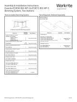
Parts Included: Chain Segments Trough Mount Kit Desk/Floor Mount Kit
Required & Sold Separately Required Tools
Assembly & Installation Instructions:
Cable Management Kit for Benching & Daisy Chain Power
Determine Cable Management Chain Length Needed:
Assemble Cable Management Chain Segments (A) to create chain needed for the following scenarios:
A Cable Management Chain Segments
Qty: 4 B Cable Trough Hanger
Qty: 2 D Floor Plate
Qty: 1
F #6 × " Phillips Washer-
Head Screw
Qty: 1
E Desk Mount
Receptacle
Qty: 1
C
Interchange Connector
Qty: 1
ACC-PWR-CBLCHAIN-X ACC-PWR-CHTRMT-X ACC-PWR-CHFLRMT-X
"Power In" Floor to Cable Trough : 28 (minimum*)–32 Links
Side to Side with Inlay Power Module Workcenters: 27 links
Side to Side with Recessed Power Module or Back to Back Workcenters: 28 links
a
a
b
c
b
c
b
1
8 Links + 8 Links + 8 Links + 3 Links = 27
8 Links + 8 Links + 8 Links + 4 Links = 28
8 Links + 8 Links + 8 Links + 4 Links 4 extra links = 28–32
Underside view 4-pack benching system with
Cable Troughs and Daisy Chain Power
Side to Side
or
Floor to Cable Trough:
* 28 links is minimum for full
height range of workcenter.
Back to Back
A
A
A

Workrite Ergonomics | 800.959.9675 www.workriteergo.com 2 of 6
Expand All Segments to Lock/Use Position
Chain Segments are shipped compressed, in a "Stored" position. Pull all links to lock into the Lock/Use position.
Your cable management chain will flex one direction and be rigid in the other.
Note: If links are not fully extended into
the Lock/Use position, the links will kink as
shown to the right. Simply pull the links until
the pin seats into the Use/Lock position.
Assemble Chain From Segments
To assemble your chain you will need to attach the eight link chain segments
together:
Align pin with grove.
Insert ball into socket.
Rotate the link 45° in the "assembly" position.
Pull the segments into the "Lock/Use" position. The link will *snap* into place.
Remove links on the last Chain Segment (A) to make the final desired length by
reversing the steps above.
2
3
a
aa
a
b
b
c
d
d
c
Groove Pin
Stored position
Socket Ball
Stored position
Assembly position
Lock/Use position
Lock/Use position
Pin not snapped into Lock/Use position Correct
Side view
Detail view
Pull

Workrite Ergonomics | 800.959.9675 www.workriteergo.com 3 of 6
Assemble Floor to Cable Trough Chain
Note: If you did not purchase the Cable Trough Kit,
skip to Step 11.
Slip the Cable Trough Hanger (B) over the male end
of the Chain (A).
Rotate 90° and lock in place by pulling.
Insert the Floor Plate (D) to the female end of the
chain, rotate and lock in place by pulling.
Place Cable Manager Chain Over Power In Feed Cable
With Benching Daisy Chain Power System installed, place Cable Manager Chain over the Power In Feed Cable
(#ACC-PWR-IN-HDWR-B). Slip the cables through the slits in the chain links making sure the Power In Feed
Cables are in the correct quadrant as shown below.
Note: Other cables, such as data are easier to install once Cable Mangers are in place.
Attaching Power Entry Cable Chain to Trough
Attach the Cable Trough Hanger (B) to the Cable
Trough by hooking the Mount onto the Cable Trough
Hook.
Note: Be sure to orient the Mount so the chain flexes
in the desired direction. For "power in" applications
the Mount will hang "side to side" so the chain and
associated cables will exit from underneath the
benching system.
90°
*snap*
90°
*
snap
*
90°
*snap*
Cable Trough Mount
Side to Side
Cable Trough Mount
Side to Side
4
5
6
a
b
c
ab
c
Cable Trough
Hooks
(side to side)
Cable Manager exits to side.
Cable Trough Mount
Side to Side
Power In Feed Cable
through this quadrant
B
B
A
A
D

Workrite Ergonomics | 800.959.9675 www.workriteergo.com 4 of 6
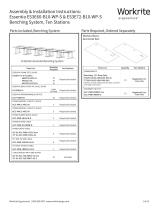
Assemble Side to Side and Back to Back Chain
Slip the Cable Trough Hanger (B) over the male
end of the chain. Rotate 90° and lock into place
by pulling.
Attach the Interchange Connector (C) to the
female end of the chain in the same manner as
the links attach creating a second male end.
Slip the Cable Trough Hanger (B) over the (now)
male end of the chain, rotate 90° and lock into
place by pulling.
You now have a chain with Cable Trough Hangers
(B) on both ends.
Place Cable Manager Chain Over Back to Back Power System Cable
Note: If you did not purchase the Benching Daisy Chain Power System, skip to Step 10.
With Benching Daisy Chain Power System installed, place Cable Manager Chain over the Back to Back Cable
(#ACC-PWR-JBBCBL-54-B). Slip the cables through the slits in the chain links making sure the Back to Back
Cable is in the correct quadrant as shown below.
Note: Other cables, such as data are easier to install once Cable Mangers are in place.
Cable Trough Mount
Back to Back
Back to Back
90°
90°
*snap*
*snap*
90°
90°
*snap*
*snap*
90°
*snap*
90° 90°
*snap*
*snap*
7
8
a
b
c
c
a
b
Male end
Female end converting to male end
Final Assembly
Cable Trough Mount
Back to Back
Back to Back Cable
through this quadrant
B
B
C
A

Workrite Ergonomics | 800.959.9675 www.workriteergo.com 5 of 6
Place Cable Manager Chain Over Side to Side Power System Cable
Note: If you are installing on a single pair of benching workstations, skip to Step 10.
With Benching Daisy Chain Power System installed, place Cable
Manager Chain over the Side to Side Cable (#ACC-PWR-JSSCBL-
50-B). Slip the cables through the slits in the chain links making
sure the Side to Side Cable is in the correct quadrant as shown
below.
Note: Other cables, such as data are easier to install once Cable
Mangers are in place.
Attaching Side to Side and Back to Back Chain to Trough
Attach the Cable Manager Chain with Cable Trough Hanger (B) to the Cable Trough by hooking the Hanger onto
the Cable Trough Hooks.
Note: Be sure to orient the Cable Trough Hanger so the chain flexes in the desired direction. For "Side to
Side" applications the Cable Trough Hanger will hang so the chain and associated cables will connect to the
workstation next to it. For "Back to Back" applications the Cable Trough Hanger will orient so the chain and
associated cables will connect to the workstation behind it.
9
Side to Side
10
Cable Trough Hooks
(side to side)
Cable Trough Hooks
(back to back)
Underside view 4-Pack benching system with
Cable Troughs and Daisy Chain Power
Cable Trough Mount
Side to Side
Side to Side Cable
through this quadrant
Cable Trough Mount
Side to Side
B
B

Workrite Ergonomics | 800.959.9675 www.workriteergo.com 6 of 6
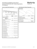
Drill, " drill bit, #2 tip Phillips screwdriver or
drill/driver.
Daisy Chain Power System, Cable Management Trough,
Rigid Modesty Panel
Assemble Floor to Desktop Chain
Insert any cabling in chain prior to mounting to Workcenter.
Assemble Cable Management Chain Segments (A) to create Floor to Desktop (no Cable Trough): 30–32 Links
Parts Included: Chain Desk/Floor Mount Kit
Required Tools
Optional & Sold Separately
Assembly & Installation Instructions:
Cable Management Kit for Freestanding Desk
ACC-PWR-CBLCHAIN-X ACC-PWR-CHFLRMT-X
Attaching Power Entry Cable Chain to Desktop
Attach the Desk Mount Receptacle (E) to the
underside of the desktop using the #6 × "
Phillips Washer Head Screw (F). Use ⅛" drill bit
to drill a pilot hole at the mounting locations.
You may wish to mark your drill bit so you do not
drill any more than ¾" deep and damage your
worksurface top.
*Do not drill all the way through worksurface!
Attach male end of chain onto Desk Mount
Receptacle (E). Rotate 45° and lock into place by
pulling.
Note: Be sure to orient the Receptacle so the
chain flexes in the desired direction. For typical
applications the Mount will hang "side to side"
so the chain and associated cables will exit from
underneath the benching system.
Insert the Floor Plate (D) to the female end of the
chain, rotate and lock in place by pulling.
1500296 Rev B
A Cable Management Chain Segments
Qty: 4 D Floor Plate
Qty: 1
F #6 × " Phillips Washer-Head
Screw
Qty: 1
E Desk Mount Receptacle
Qty: 1
Review Steps 2 & 3 for instruction on assembling chain segments.
90°
*snap*
11
12
8 Links + 8 Links + 8 Links + 6 Links + 2 links optional = 30–32
Exits to side.
a
a
b
b
Pre-drill*
F
E
A
c
cA
D
/