Page is loading ...

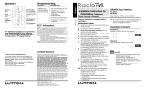
Emergency Lighting Interface LUT-ELI-3PH
|
Installation Guide
LUT-ELI-3PH Installation Guide Lutron® | 1
´FACP´ N/C
CONTACTS
´FACP´ N/O
CONTACTS
12 11 10 98765432112 11 10 987654321
CLASS 2 LOW VOLTAGE WIRING
GND
SENSE
DRAIN
MUX
MUX
+24VFW
COMMON
NOT USED
LED1
LED3
LED2
RADIOTOUCH
PHASE
FACF
S1
TEST
System Ratings
• Voltage:100-347V 50/60Hz30mA
• Current:20Amaximumcircuitbreaker
ForusewithLutron®:GRAFIK Eye®GP,LP,andXP
panels;LCP128TMpanels;Softswitch128panels;
EcoSystem®lightingcontrolsystem;EnergiSavr
NodeTM units;Quantum® systems;GRAFIK EyeQS
units,andRadioTouch®lightingcontrollers.
Note:Thisdevicedoesnotprovideemergencypower.
AnEmergency(Essential)powersourcemustbe
provided.
Please read this guide before installing.
Contents Page
Ratingsandmodelnumberoverview............................1
MountingtheInterface.................................................2
WiringOverviewforLUT-ELI-3PHunitson:
RadioTouchSystems...............................................2
Panel-BasedSystems..............................................4
EcoSystemorQuantumbussupplies.......................8
GRAFIKEyeQSunits...............................................9
EnergiSavrNodeunits..........................................10
EmergencyPowerModeSetup:LCPPanels..............11
NECClass2/PELVWiringtoFireAlarm
ControlPanel(FACP).............................................12
Troubleshooting
RadioTouch ............................................................13
PanelBasedSystems............................................14
EnergiSavrNode Installations................................15
EcoSystemorQuantumSystem............................16
GrakEyeQSInstallation.......................................17
Listing
TheEmergencyLightingInterface–LUT-ELI-3PHis
UL924Listedas“EmergencyLightingandPower
Equipment”.Theinterfaceshallbeusedwith:Lutron
GRAFIK EyeGP,XP,andLPpanels;LCP128panels;
Softswitch128panels;EcoSystem;Quantum;GRAFIK
Eye QS,RadioTouchcontrollers,andEnergi Savr
Nodeunits.
Description
TheLUT-ELI-3PHunitsensesthelinevoltageon
allthreephasesorasinglephaseandcontrolsthe
emergencysignaltothefollowingcompatibleLutron
products/systems:
• CircuitSelectorforGP,LP,XPpanels
• LCP/XPScontrollerforLCP128,and
Softswitch 128panels
• EcoSystemBusSupply
• QuantumBusSupply
• Grafik EyeQSunit
• RadioTouchcontroller
• Energi Savr Nodeunit
Whenoneormorephasesofnormalpowerarelost,
theLUT-ELI-3PHunitsendsasignaltotheaffected
device(s),activatingtheemergencymode.Anylights
controlledbythesedeviceswillgototheemergency
lightlevelsetting(factorysetto100%intensity).When
normalpowerisrestored,thelightswillreturntotheir
previousintensities.
Important Safeguards
• Followallnationalandlocalelectricalcodesandsafety
standards.
• Turnoffpowerbeforeinstallation.
• LinevoltageinputtotheLUT-ELI-3PHunitmustbe
fromtheNORMAL(non-essential)powersource.
• Readandfollowallsafetyinstructions.
• Forindooruseonly.
• Equipmentshouldbemountedinlocationsand
atheightswhereitwillnotreadilybesubjectedto
tamperingbyunauthorizedpersonnel.
• Donotusethisequipmentforotherthanintendeduse.
• Allservicingshouldbeperformedbyqualiedservice
personnel.
System Limits (per / LUT-ELI-3PH)
• 32circuitselectors
• 100RadioTouchControllers
• 32EcoSystembussupplies
• 32Quantumbussupplies
• 32Energi Savr Nodeunits
• 32LCP/XPSControllers

Emergency Lighting Interface LUT-ELI-3PH
|
Installation Guide
Lutron® | 2 LUT-ELI-3PH Installation Guide
Mounting the Interface
1. Turnpoweroff.
2. Wirethelinevoltageleadsthatprotrudefrombackof
LUT-ELI-3PHunitintothejunctionbox.
3. MounttheLUT-ELI-3PHunitontoa4x4-inch
(102x102mm)junctionbox(notincluded,but
available;Lutronpartnumber241-496).
4. Besureallthepowerwiresarecompletelyinsidethe
junctionboxbeforetighteningthemountingscrews.
5. Removefrontenclosurecovertoexposetheterminal
blocks,testswitch,andstatusLEDs.
6. InserttheNEC®Class2/PELVwiresthroughknockouts
intheLUT-ELI-3PHenclosureasshowninthediagram.
7. ConnecttheNECClass2/PELVwirestotheLutron®
productorsystem,whichtheLUT-ELI-3PHwillbe
controlling.Specicwiringtothesedeviceswillbe
describedinthefollowingsections.
8. Reinstallfrontenclosurecover.
Note:CalltheLutronTechnicalSupportCenterat
(800)523-9466forrestrictionsandwiringrequirements
foremergencyxtures(xturesthatneverturnoffor
haveabatterybackupballastinthexture).
InsertNECClass2/PELV
wiresthroughknockouts
4x4in
(102x102mm)
JunctionBox
SideView
(Cross-Section)
Installing a LUT-ELI-3PH Unit in a
RadioTouch® System
Line Voltage Connections
WARNING! Danger of shock. May result
in serious injury or death.DONOTWIRE
WHENLIVE!Switchoffpowertoallpower
feedsviacircuitbreakerorisolatorbefore
wiringorservicingtheLUT-ELI-3PHunitand
RadioTouchSystem
Buttons and LEDs in the unit are used for
troubleshooting. If wiring is exposed when accessing
buttons and LEDs, the unit must be accessed by a
certified electrician, following local codes.
Note: Providepropershort-circuitandovercurrent
protectionatthedistributionpanel.Maximumcircuit
breakerratingof20A.
Single-PhaseWiring
Ground
Neutral
Hot
Normal
Power
Normal
Lights
Red
Red
Red
White
Green
Three-PhaseWiring
Ground
Neutral
PhaseC
PhaseB
PhaseA
Normal
Power
Normal
Lights
Red
Red
Red
White
Green
WALL
LUT-ELI-3PH
UNIT
Figure #1 Figure #2

Emergency Lighting Interface LUT-ELI-3PH
|
Installation Guide
LUT-ELI-3PH Installation Guide Lutron® | 3
1234 5678 910111213141516
CLASS 2 LOW VOLTAGE WIRING
1 2345
Power
Status Program
Burn-In
123
378910 11 12 13 14 15 16
CLASS 2 LOW VOLTAGE WIRING
1 2345
Power
Status Program
Burn-In
123
4 5612
´FACP´N/C
CONTACTS
´FACP´N/O
CONTACTS
CLASS2LOWVOLTAGEWIRING
GND
SENSE
DRAIN
MUX
MUX
+24VFW
COMMON
NOTUSED
LED1
LED3
LED2
RADIOTOUCH
PHASE
FACF
S1
TEST
12 11 10 98765432112 11 10 987654321
RadioT o uch
TM
C o o p er sbur g, PA1 803 6 U S A
R T A-RX-F-SC
LISTED243C
Ind.Cont.Eq.
12
345678910
1 1
12 1 3 14
15 16
Occ.Com
OccSig
24V
CirCom
CCO1
CCO2
CCO3
CCO4
CCO5
CCOCom
+
_
PELV(Class2:USA)
PWR STAT
PROG
100Hr/100%
®
PSSig
P/N500-10634
©
2006LutronElectronicsCo.,Inc.
12345
ON
PowerWiringCableadod ePoderC âblaged'alimentation
DistributionPanel
PaneldeDistribución
PanneaudeDistribution
Ground/Tierra/Terre
Neutral/Neutro/Neutre
Black/Negro/Noir
Green/V erde/V ert
White/Blanco/Blanc
Red/Rojo/RougeOR
Orange/Anaranjado/Orange*
SwitchedHot/InterruptorVivo/CourantCommuté
DimmedHot/AtenuadorVivo/CourantTamisé*
Dimmed Hot is for use only with Lutron Hi-Lume FDB-series or Eco-10
ECO-series dimming ballasts.
El Atenuador V ivo es para ser utilizado únicamente con las series de balastos
de atenuaci ó n Hi-Lume FDB o Eco-10 ECO de Lutron.
Courant T amisé doit être utilisé seulement avec le Hi-Lume FDB-series ou avec
le ballast de gradation Eco-10 ECO-series de Lutron.
P/N 500-10634
*
*
*
Hot/Vivo/Chargé
For 120 V~ use black wire, cap red. For 277 V~ use red wire, cap black.
Blue/Bleu/Azul
120V277V
*
USA,Canada
1-800-523-9466
Mexico
1-888-235-2910
®
www .lutron.com
RTA-RX-F-SC
15V
CONFIGURACIONES
REGLAGES
SETTINGS
R e fertotheInstallersGuideformore
detailedinstructions.
ConsultelaGuíadeInstaladorespara
informaciónmásdetallada.
RéférerauGuided’installationpourplusde
renseignementsdétaillés.
120/277V60Hz
16AMax.
0-10
V
Red&Black/Rojo&Negro/Rouge&Noir
LUT-ELI-3PHUnit RadioTouchUnitA RadioTouchUnitB
120/277V
feedbackup/
Emergency
power
120/277V
feedbackup/
Emergency
power
FlipDip
Switch2to
thedown
position
FlipDip
Switch2to
thedown
position
(2)Signal
(6)CircuitCommon
Toadditional
RadioTouch
controllers
(100maximum)
AdditionalRadioTouchControllerforBackup/
EmergencyLight(s)
Availablepowerfromthisunit
fordaylightsensorsmustbe
deratedto15mA.
(8) (2)(7) (4)(1) (6)
Installing a LUT-ELI-3PH Unit in a
RadioTouch® System (continued)
NEC® Class 2/PELV Connections
Note: Whenwiringforabackup/emergencysourceof
power,theRadioTouchController(modelsRTA-RX-F,
RTA-RX-F-SC,RTA-RXSW),beingusedforthebackup/
emergencylights(UnitAandB)cannotbecontrolledby
anoccupancysensor.UnitsAandBDIPswitch2must
beinthedownposition.
NEC Class 2/PELV Wiring to RadioTouch
Controllers
OneLUT-ELI-3PHcanbeconnectedinparallelwithup
to100RadioTouchControllers.
1. FlipDIPswitch2ontheRadioTouchControllertothe
downposition.
2. Disconnectanyoccupancysensorswiredtothe
RadioTouchController.
3. Makethefollowingconnections.
From LUT-ELI-3PH Unit To RadioTouch Controller
Terminal8(+VInput) Terminal4(24V ),UnitAonly
Terminal7
(CircuitCommon)
Terminal6(CirCom)
Terminal1(Signal) Terminal2(OccSig)
Test the System
Pleaseperformthefollowingteststoensureproper
installation.
1. TurnoffoneoftheNormal(Non-Essential)phase(s)
breaker(s)thattheLUT-ELI-3PHunitismonitoring.
You should see the following:
•AlllightscontrolledbyEmergency(Essential)panel
willgotoFULLINTENSITY(factoryset).
•PHASEON/OFFstatusIndicator(green)willturn
OFFastheabovetestcreatesaphasefailure.
•Uponturningthebreakerbackon,alllightsshould
returntotheirpreviousintensity.
2. PressandholdswitchSW1ontheLUT-ELI-3PHunit.
You should see the following:
•TESTLED(orange)willturnON.
•AlllightscontrolledbyEmergencyRadioTouch
controllerwillgotoFULLINTENSITY(factoryset).
Note: PHASEON/OFFstatusindicator(green)will
notturnOFFastest#2doesnotcreateaphase
failure.
•UponreleasingswitchSW1,alllightswillreturnto
theirpreviousintensities.
Note:OnlyoneRadioTouchunitcanhaveits
24V (number4)terminalconnectedtoterminal
8(+VInput)ontheLUT-ELIunitregardlessofthe
numberofwiredRadioTouchunits.
(2) (6)

Emergency Lighting Interface LUT-ELI-3PH
|
Installation Guide
Lutron® | 4 LUT-ELI-3PH Installation Guide
Installing a LUT-ELI-3PH Unit in a
Panel-Based System
Line Voltage Connections
WARNING! Danger of shock. May result
in serious injury or death.DONOTWIRE
WHENLIVE!Switchoffpowertoallpower
feedsviacircuitbreakerorisolatorbefore
wiringorservicingtheLUT-ELI-3PHunitand
Panel-BasedSystem.
Buttons and LEDs in the unit are used for
troubleshooting. If wiring is exposed when accessing
buttons and LEDs, the unit must be accessed by a
certified electrician, following local codes.
Note: Providepropershort-circuitandovercurrent
protectionatthedistributionpanel.Maximumcircuit
breakerratingof20A.
WiringfromMainswithGP,LP,XP,andXPS/LCPPanels
PhaseA
Normal
Power
Normal
topanel
Red
Red
Red
White
Green
PhaseB
PhaseC
Neutral
Ground
WiringfromNormal(Non-Essential)GPPanel
DH1 SH1 H1 DH2 SH2 H2 DH3 SH3 H3
´FACP´N/C
CONTACTS
´FACP´N/O
CONTACTS
12 11 10 987654321
CLASS2LOWVOLTAGEWIRING
GND
SENSE
DRAIN
MUX
MUX
+24VFW
COMMON
NOTUSED
LED1
LED3
LED2
RADIOTOUCH
PHASE
FACF
S1
TEST
Red
Red
Red
White
Green(togroundlug)
Typicalload
circuit
Control
wiringto
circuit
selector
GP3panelshown
Branch
circuit
breakers
Normalpower
feedwiring
Terminal
blocks
Neutral
block
Groundlug
N

Emergency Lighting Interface LUT-ELI-3PH
|
Installation Guide
LUT-ELI-3PH Installation Guide Lutron® | 5
Installing a LUT-ELI-3PH Unit in a
Panel-Based System (continued)
NEC® Class 2/PELV: USA Connections
Notes
• PullNECClass2/PELVwiringforsystem
communications.
• NECClass2/PELVwiringmustbedaisy-chained.
• NECClass2/PELVwiringmustberunseparatelyfrom
line(mains)voltage.
• ALUT-ELI-3PHunitcanbeplacedanywhereonthe
powerpanellink.
Wiring Notes
• NECClass2/PELVwiringlinkis500to2000feet
(152to610m),useLutron®cableGRX-CBL-46L:
-Two12AWG(2.5mm
2
)forcontrolwiring
(+Vandcom)
-Onetwisted,shieldedpair22AWG(0.5mm
2
)
fordatalink
-One18AWG(1.0mm
2
)forsenselinebetween
panels.
• Lutronhasalsoapprovedsmaller-gaugecable
fromBelden®,LibertyWire&Cable®,AlphaWire
Company,andSignatureWireCorp.AskforLutron
GRAFIKEye®Cable.
Paneltopanelwiring
Seeaboveforwiringnotes
Dimmingpanel
Powerpanellink
LUT-ELI-3PHUnit
Processorpanel
Wallstationlinks

Emergency Lighting Interface LUT-ELI-3PH
|
Installation Guide
Lutron® | 6 LUT-ELI-3PH Installation Guide
´FACP´N/C
CONTACTS
´FACP´N/O
CONTACTS
CLASS2LOWVOLTAGEWIRING
GND
SENSE
DRAIN
MUX
MUX
+24VFW
COMMON
NOTUSED
LED1
LED3
LED2
RADIOTOUCH
PHASE
FACF
S1
TEST
DataAOKPower DataBOK
1234D5
Common
Common
+24VFW
Sense
MUX
MUX
Drain
Drain
MUX
MUX
Circuit
1
2
Link
A
1
2
3,4
5
1
2
3,4
DataAOKPower DataBOK
1234D5
CD
Common
Common
+24VFW
Sense
MUX
MUX
Drain
Drain
MUX
MUX
Circuit
1
2
1234D5
S
ELECT
C
IRCUIT
S
ELECT
C
IRCUIT
Link
B
Link
A
Link
B
1234D5
CD
12 11 10 98765432112 11 10 987654321
Shield/
Drain
Tolightingcontrols
orprocessors
Control
Wiring:
(2)12AWG
(2.5mm
2
)
1:Common
2:24V
DataLink:
(1)shielded,
twistedpair
18AWG
(1.0mm
2
)
3:MUX
4:MUX
Sense:
(1)18AWG
(1.0mm
2
)
5:Senseline
Installing a LUT-ELI-3PH Unit in a
Panel-Based System (continued)
NEC® Class 2/PELV Panel to Panel Wiring Notes
• EmergencyPower:Theadditional18AWG(1.0mm
2
)wire
isa“sense”linefromterminal12ontheLUT-ELI-3PH.This
senselineallowsanEmergency(Essential)lightingpanelto
“sense”whenNormal(Non-Essential)powerislost.Ifmore
thanoneemergencylightingpanelneedstosenseNormal
(Non-Essential)fromaspecicLUT-ELI-3PHunit,youmay
havetorunadedicatedwirebetweeneachLUT-ELI-3PH
unitandEmergency(Essential)panel(s).
• Shield/Drain:Connectshieldingasshownbelowinwiring
exampleA:
-DonotconnecttoGround(Earth)orcircuitselector.
-Connectthebaredrainwiresandcutofftheoutside
shield.
Connections
LUT-ELI-3PH Circuit Selector
Terminal12(Sense) Terminal5(Sense)
Terminal11(Drain) TerminalD(Drain)
Terminal10(MUX) Terminal4(MUX)
Terminal9(MUX) Terminal3(MUX)
Terminal8(+VInput) Terminal2(+24VFW)
Terminal7
(CircuitCommon)
Terminal1
(Common)
Panel1 Panel2
Data A OK
Data B OK
Power OK
12345D
2
1
Circuit
A B
Common
24VFW
MUX
MUX
Drain
Sense
Comm
Drain
MUX
MUX
C
1
234
D
5
D
Link Link
S
ELECT
C
IRCUIT
S
ELECT
V
ALUE
V
IEW
V
ALUE
(4)12AWG
(2.5mm
2
)
• EachNECClass2/PELVterminalcanacceptonly
two18AWG(1.0mm
2
)wires.Two12AWG
(2.5mm
2
)conductorswon'tt.Connectasshown
belowinwiringexampleB.
Wiring Example A
Wiring Example B

Emergency Lighting Interface LUT-ELI-3PH
|
Installation Guide
LUT-ELI-3PH Installation Guide Lutron® | 7
Installing a LUT-ELI-3PH Unit in a
Panel-Based System (continued)
Setting the Circuit Selector Normal/Emergency
Switch (SW6) Position
PanelsareshippedwithSW6(locatedatthebaseofeach
CircuitSelector)inthemiddleposition.Terminal5(sense)
hasnoaffectonthecircuitselectoroperation.
All Emergency Panels
• MoveSW6totherightEmergency(Essential)position.In
thisarrangement,theLUT-ELI-3PHunitwillbetheonlyunit
controllingthesenseline.Ifoneormorephasesgodown,
theLUT-ELI-3PHunitsendsasignalthroughthesense
linetoEmergency(Essential)panel(s).Thelightscontrolled
bythesepanelswillgoto‘ord’overridelevels(factoryset
tofullintensity).Whennormalpowerisrestored,lightswill
returntotheirpreviousintensities.
Note: Whenin‘ord’overridemode(factorysettofull
intensity),‘ord’willappearonvaluedisplaytoconrmthat
Emergency(Essential)positionisineffect.
Test the System
Pleaseperformthefollowingteststoensureproper
installation.
1. TurnoffoneoftheNormal(Non-Essential)phase(s)
breaker(s)thattheLUT-ELI-3PHunitismonitoring.
You should see the following:
•PHASEON/OFFstatusIndicator(green)willturnOFFas
theabovetestcreatesaphasefailure.
•CircuitselectoronEmergency(Essential)panelwillgoto
‘ord’overridemode.
•AlllightscontrolledbyEmergency(Essential)panelwillgo
toFullIntensity(FactorySet).
•ThecircuitselectorinEmergency(Essential)panelwillread
‘ord’onthevaluedisplaywheninEmergencymode.
•AlllightscontrolledbyNormal(Non-Essential)panelwill
freezeattheirrespectiveintensities.
2. PressandholdswitchSW1ontheLUT-ELI-3PHunit.
You should see the following:
• TESTLED(orange)willturnON.
Note: PHASEON/OFFstatusindicator(green)willnotturn
OFFastest#2doesnotcreateaphasefailure.
• CircuitSelectoronEmergency(Essential)Panelwillgoto
‘ord’overridemode.
• AlllightscontrolledbyEmergency(Essential)panelwillgo
toFULLINTENSITY(factoryset).
• ThecircuitselectoronEmergency(Essential)panelwill
read‘ord’onthevaluedisplaywheninEmergencyMode.
• AlllightscontrolledbyNormal(Non-essential)panelwill
freezeattheircurrentintensities.
• UponreleasingswitchSW1,alllightswillreturntotheir
originalintensities.
DataAOK
DataBOK
PowerOK
12345D
Load Type (See Instructions)
High-End Trim
Circuit Level
Low-End Trim
5
4
3
Value
Link A
Link B
2
1
Circuit
A B
Common
24VFW
MUX
MUX
Drain
Sense
Comm
Drain
MUX
MUX
C
1
234
D
5
D
Link Link
1-1
2-1
2-2
3-1
4-1
Incandescent
Neon / CC
Non-Dim
---
Unassigned
Fluorescent Lutron Tu-Wire
TM Ballast
Address ('Ad' displayed)
Zone Assignment w/ Circuit Schedule
Zone Assignment w/ Zone CaptureTM
Warning - Read instructions to set the Load
Type. Instructions show more load types.
Load Type Quick Reference:
S
ELECT
C
IRCUIT
S
ELECT
V
ALUE
V
IEW
V
ALUE
S
ELECT
V
ALUE
D
ISPLAYED
Normal Emergency
(Essential)(Non-Ess)
Fluorescent Lutron Hi-lume
R FDB Ballast
LINK 1 LINK 2
CircuitSelectorinNormal
(Non-Emergency)Panel
CircuitSelectorin
Emergency(Essential)Panel
Switchis
incenter
position
Switchis
movedto
theright
(emergency)
position

Emergency Lighting Interface LUT-ELI-3PH
|
Installation Guide
Lutron® | 8 LUT-ELI-3PH Installation Guide
Installing a LUT-ELI-3PH Unit in an
EcoSystem® or Quantum® System
Line Voltage and NEC® Class 2/PELV Connections
WARNING! Danger of shock. May result in
serious injury or death.DONOTWIREWHEN
LIVE!Switchoffpowertoallpowerfeeds
viacircuitbreakerorisolatorbeforewiringor
servicingtheLUT-ELI-3PHunitandEcoSystem
lightingcontrolsystemorQuantumsystem.
Buttons and LEDs in the unit are used for
troubleshooting. If wiring is exposed when
accessing buttons and LEDs, the unit must be
accessed by a certified electrician, following
local codes.
Note: Providepropershort-circuitandovercurrent
protectionatthedistributionpanel.Maximumcircuit
breakerinstallationof20A.
ALutron®PP-120HorPP-277Hpowerpackmustbe
usedtopowertheLUT-ELI-3PHunitwhenusedwitha
bussupply.Boththepowerpackandthebussupplies
mustbefedfromanormal/emergencysupply.
´FACP´N/C
CONTACTS
´FACP´N/O
CONTACTS
CLASS2LOWVOLTAGEWIRING
GND
SENSE
DRAIN
MUX
MUX
+24VFW
COMMON
NOTUSED
LED1
LED3
LED2
RADIOTOUCH
PHASE
FACF
S1
TEST
E2
E1
1
2
3
4
5
6
7
8
E2
E1
EM C
12 11 10 98765432112 11 10 987654321
24V
(Red)
Common
(Black)
Hot
Neutral
From120or277V
Normal/Emergencysupply
Common
Emerg.
signal
Connectupto8
Quantumhubs
100-277V
Normal/Emergency
supply
Power
pack*
WiringtoQuantumsystems
*PP-120HorPP-277H
WiringtoEcoSystemBusSupply
´FACP´ N/C
CONTACTS
´FACP´ N/O
CONTACTS
12 11 10 987654321
CLASS 2 LOW VOLTAGE WIRING
GND
SENSE
DRAIN
MUX
MUX
+24VFW
COMMON
NOT USED
LED1
LED3
LED2
RADIOTOUCH
PHASE
FACF
S1
TEST
100-347V
50/60Hz
3-phase
normalsupply
SeeFigure#1
orFigure#2
onpage2of
thisguide.
Common
24V
24V
(Red)
Common
(Black)
Common
(pin5)
Emerg.
signal
(pin6)
Hot
Neutral
Power
pack*
From120or277V
Normal/Emergency
supply
Bussupply Bussupply
Connectupto32
bussupplies
100-277V
Normal/
Emergency
supply
*PP-120HorPP-277H
(8) (7) (1)
(8) (7) (1)

Emergency Lighting Interface LUT-ELI-3PH
|
Installation Guide
LUT-ELI-3PH Installation Guide Lutron® | 9
Installing a LUT-ELI-3PH Unit in a
GRAFIK Eye® QS Unit
NEC® Class 2/PELV Connections
WARNING! Danger of shock. May result in
serious injury or death.DONOTWIREWHEN
LIVE!Switchoffpowertoallpowerfeeds
viacircuitbreakerorisolatorbeforewiringor
servicingtheLUT-ELI-3PHunitandGRAFIK Eye
QSunit.
Buttons and LEDs in the unit are used for
troubleshooting. If wiring is exposed when
accessing buttons and LEDs, the unit must be
accessed by a certified electrician, following
local codes.
WiringtoaGRAFIK EyeQSControlUnit
Notes
• Providepropershort-circuitandovercurrent
protectionatthedistributionpanel.Maximum
circuitbreakerinstallationof20A.
• Whennormalpowerlossisdetectedatthe
LUT-ELI-3PHunit,allzonesintheGRAFIK EyeQS
unitswillgototheiremergencystates.
• TheGRAFIK EyeQSunitMUSTbepoweredfroma
normal/emergencypowerfeed.
Note:For1-phase2-wireapplication,connectphaseA,B,andCwireson
LUT-ELI-3PHtogetherforphasesensing.
´FACP´N/O
CONTACTS
TAGEWIRING
GND
SENSE
NOTUSED
LED1
LED3
LED2
RADIOTOUCH
PHASE
FACF
S1
TEST
12 987654321
´FACP´
CP´N/O
C
CONTACTS
TAGEWIRING
S
ENS
E
N
O
T
US
E
D
LED
RADI
O
T
OUC
H
1
2
876543
7
98765432
1
´FACP´N/C
CONTACTS
´FACP´N/O
CONTACTS
CLASS2LOWVOLTAGEWIRING
SENSE
DRAIN
MUX
MUX
+24VFW
COMMON
NOTUSED
LED3
RADIOTOUCH
12 11 10 9 87654321
Signal
+24V
Common
(3)18AWG
GRAFIK EyeQSunitQSGRJmodel(backview)
Normal/Emergency
20A120V
1-Phase2-Wire
powerfeed
(3)12AWG(2.5mm²)
120-127V
or
220-240V
distributionpanel
100-347V
50/60Hz
3-phaseNormalsupply
SeeFigure#1orFigure#2
onpage2ofthisguide.
CCI SIG
24 V
CCI Com
(8) (7) (1)

Emergency Lighting Interface LUT-ELI-3PH
|
Installation Guide
Lutron® | 10 LUT-ELI-3PH Installation Guide
´FACP´ N/C
CONTACTS
´FACP´ N/O
CONTACTS
12 11 10 98765432112 11 10 987654321
CLASS 2 LOW VOLTAGE WIRING
GND
SENSE
DRAIN
MUX
MUX
+24VFW
COMMON
NOT USED
LED1
LED3
LED2
RADIOTOUCH
PHASE
FACF
S1
TEST
Installing a LUT-ELI-3PH Unit with an
Energi Savr NodeTM Unit(s)
NEC® Class 2/PELV Connections
WARNING! Danger of shock. May result
in serious injury or death.DONOTWIRE
WHENLIVE!Switchoffpowertoallpower
feedsviacircuitbreakerorisolatorbefore
wiringorservicingtheLUT-ELI-3PHand
Energi Savr Nodeunit.
Buttons and LEDs in the unit are used for
troubleshooting. If wiring is exposed when accessing
buttons and LEDs, the unit must be accessed by a
certified electrician, following local codes.
Notes: Providepropershort-circuitandovercurrent
protectionatthedistributionpanel.Maximumcircuit
breakerinstallationof20A.
• ALutron®PP-120HorPP-277Hpowerpackmustbe
usedtopowertheLUT-ELI-3PHunitwhenusedwithan
Energi Savr Nodeunit(s).Boththepowerpackandthe
Energi Savr Nodeunit(s)mustbefedfromanormal/
emergencysupply.
• WhennormalpowerlossisdetectedattheLUT-ELI-3-
PHunit,allzonesintheEnergi Savr Nodeunitwillgoto
theiremergencystates.
• TheEnergi Savr NodeunitMUSTbepoweredfroma
normal/emergencypowerfeed.
WiringfromEnergi Savr NodeUnits
Note: For1-phase2-wireapplication,connect
phaseA,B,andCwiresonLUT-ELI-3PHtogether
forphasesensing.
Connections
LUT-ELI-3PH Energi Savr Node Unit Power Pack
Terminal8(+VInput) ------------------------- RedWire
Terminal7
(CircuitCommon)
Com
(EmergencyCCIInput)
BlackWire
Terminal1(Signal) Emerg(EmergencyCCIInput) ---------------
*NECClass2/PELVWiring
18AWG(1.0mm²)
Note:
Upto32QSN-4T16-Sor
QSN-4S16-Sunitscanbe
connectedto1LUT-ELI-3PH
*Signal
*Common(Black)
*+24V (Red)
PP-120Hor
PP-277H
*Signal
*Common
*Common
2#12
InputPower
(120or277V )
Normal/EmergencyPower
(8) (7) (1)
100-347V
50/60Hz
3-phaseNormalsupply
SeeFigure#1orFigure#2
onpage2ofthisguide.

Emergency Lighting Interface LUT-ELI-3PH
|
Installation Guide
LUT-ELI-3PH Installation Guide Lutron® | 11
Emergency Power Mode
Setup: LCP128TM / Softswitch128®
with LUT-ELI-3PH
Thisstepisonlyperformedifanemergencypattern*is
neededwhennormalpowerislost.Allcontroldevice
inputsandtimeclockeventsareignoredwhilein
emergencypowermode.Thisstepwilldeneifthe
panelhasemergencycircuitsandhowtocongurethe
emergencypattern.
•Foralltheemergency(essential)lightingpanels,move
theemergency switchestotherightposition(see
illustrationbelow).
•Theessentialandnon-essentialpanelsmustbecon-
nectedbyasenselinewiredtoterminal 5onthelink
connectorontheLCP128/Softswitch128controller(see
illustrationbelow).Forwiringdetails,seetheInstallation
Guide.
*Inthisconguration,theemergency(essential)lighting
panelwill“sense”thenormalpanels’power.When
normalpowerislost,theemergencypanelwillgotothe
emergencypattern(factorysettoallcircuitsOn).When
normalpowerisrestored,lightingcircuitsandcontact
closureoutputsreturntotheirpreviousstate.
UseTerminal5toconnectasenseline
betweenemergencyandnormalpanels,
orbetweentheLUT-ELI-3PHunitandone
ormoreemergencypanels.An#18AWG
wireisrecommendedforthesenseline.
ThreepositionEmergency Switchislocatedatthe
bottomoftheLCP128/Softswitch128controller.
12345D
TopoftheLCP128/Softswitch128Controller
LeftPosition
RightPosition
(Non-Essential)
(Essential)
CenterPosition
(NoresponsetoEmergency)
Notes:
•IfUL924certicationisrequired,theLutron®
EmergencyLightingInterface(LUT-ELI-3PH)maybe
usedtomeetcode.TheLUT-ELI-3PHunitsenses
thenormal(non-essential)linevoltageonallthree
phases(3PH)ofnormalpower.Whenoneormore
phasesofpowerarelost,theLUT-ELI-3PHunitwill
sendasignaltoterminal 5ontheLCP128/Soft-
switch128controller(s).Whentheemergency
switchissettotherightposition(essential)the
emergencypatternwillberecalled.TheLUT-ELI-3-
PHunitcanbeusedwithoneormultiplepanel
systems.
•Lossofnormalpowercanbesimulatedbyturning
offallconnectednormal(non-essential)panelcontrol
breakers.
•Whentheemergencyswitchisinitscenterposition
(asshipped),terminal5thepaneldoesnotrespond
toemergency.

Emergency Lighting Interface LUT-ELI-3PH
|
Installation Guide
Lutron® | 12 LUT-ELI-3PH Installation Guide
´FACP´N/C
CONTACTS
´FACP´N/O
CONTACTS
CLASS2LOWVOLTAGEWIRING
GND
SENSE
DRAIN
MUX
MUX
+24VFW
COMMON
NOTUSED
LED1
LED3
LED2
RADIOTOUCH
PHASE
FACF
S1
TEST
12 11 10 98765432112 11 10 987654321
NormallyOpen
FACPInput
LUT-ELI-3PHunit
To24V power
FireAlarmControlPanel
(providedbyothers)
Common
Normally
open
NEC® Class 2/PELV Wiring to
Fire Alarm Control Panel (FACP)
• Useonlywithnormallyopen(terminals3and4)ornormally
closed(terminals5and6)drycontactclosure.Whenthe
propercontactstateistriggered,itmustbemaintained
fortheLUT-ELI-3PHunittogointoEmergencyMode.
Oncethecontactisreleased,theLUT-ELI-3PHunitwill
returntheGRAFIKSystemsTMGP,LP,XPpanels,XPS,
LCP,RadioTouch®controller,EcoSystem®BusSupply,
EnergiSavrNodeTMunit,orQuantum®BusSupplybackto
Normaloperationmode.
• TheLUT-ELI-3PHunitwillhaveafactoryinstalled
jumpertoprovidethenormallyclosedinputsignal
forthesupervisorycircuitwhenanormallyclosed
FACPinputisnotprovided.
• ConsultyourFireAlarmControlPanel’sinstruction
manualbeforeconnectingtotheLUT-ELI-3PHunit.
• DonotconnectanyvoltagesourcetotheFACP
inputsontheLUT-ELI-3PHunit.Ifvoltageis
providedbytheFACPandconnectedtotheLUT-
ELI-3PHunit,itcandamagetheLUT-ELI-3PHunit.
´FACP´N/C
CONTACTS
´FACP´N/O
CONTACTS
CLASS2LOWVOLTAGEWIRING
GND
SENSE
DRAIN
MUX
MUX
+24VFW
COMMON
NOTUSED
LED1
LED3
LED2
RADIOTOUCH
PHASE
FACF
S1
TEST
12 11 10 98765432112 11 10 987654321
SupervisoryCircuit
(NormallyClosed
FACPInput)
LUT-ELI-3PHunit
To24V power
FireAlarmControlPanel
(providedbyothers)
Common
Normally
closed

Emergency Lighting Interface LUT-ELI-3PH
|
Installation Guide
LUT-ELI-3PH Installation Guide Lutron® | 13
Troubleshooting RadioTouch®
Symptom Possible Cause Solution
Lightsareatfull
intensityandcan
notbecontrolled
byanaddressed
transmitter
LUT-ELI-3PHunitisnotconnected
toSignalontheRadioTouch
Controller
Connectterminal2‘OccSig’fromtheRadioTouch
Controllertoterminal1‘Signal’ontheLUT-ELI-3PHunit
Oneormoreofthephasesfeeding
theLUT-ELI-3PHunitareoff(phase
LEDontheLUT-ELI-3PHunitwill
beoff)
TurnONallnormalpowerphasestoLUT-ELI-3PHunit
Neutralisnotconnectedonthe
LUT-ELI-3PHunit(phaseLEDon
theLUT-ELI-3PHunitwillbeOFF)
Connectneutral
24V isnotconnectedonthe
LUT-ELI-3PHunit(phaseLEDon
theLUT-ELI-3PHunitwillbeOFF)
Connectterminal4‘24V ’fromRadioTouchControllerto
terminal8‘+VInput’ontheLUT-ELI-3PHunit
ThereisashortacrossFACPand
normallyopencontact(FACPLED
willbeON)
Removeshort
Lightsdonot
turnONanddo
notgotohigh
endwhenthe
testswitchis
pressed
DIPswitch2ontheRadioTouch
ControllerisintheUPposition
MoveDIPswitch2ontheRadioTouchControllertothe
DOWNposition
24V andsignalwiresare
swapped
Connectterminal4‘24V ’fromtheRadioTouch
Controllertoterminal8‘+VInput’ontheLUT-ELI-3PHunit
andconnectterminal2‘OccSig’fromtheRadioTouch
Controllertoterminal1‘Signal’ontheLUT-ELI-3PHunit
24V andcommonwiresare
swapped
Connectterminal4‘24V ’fromtheRadioTouch
Controllertoterminal8‘+VInput’ontheLUT-ELI-3PHunit
andconnectterminal6‘CirCom’fromtheRadioTouch
Controllertoterminal7‘CircuitCommon’ontheLUT-ELI-
3PHunit
Commonandsignalwiresare
swapped
Connectterminal6‘CirCom’fromtheRadioTouch
Controllertoterminal7‘CircuitCommon’ontheLUT-
ELI-3PHunitandconnectterminal2‘Occsig’fromthe
RadioTouchControllertoterminal1‘Signal’ontheLUT-ELI-
3PHunit
Lightsdonot
turnONanddo
notgotohigh
endwhenone
ormoreofthe
normalpower
phasesare
turnedOFF
DIPswitch2ontheRadioTouch
ControllerisintheUPposition
MoveDIPswitch2ontheRadioTouchControllertothe
DOWNposition
24V andsignalareswapped Connectterminal4‘24V ’fromtheRadioTouchController
toterminal8‘+VInput’ontheLUT-ELI-3PHunitand
connectterminal2‘OccSig’fromtheRadioTouchController
toterminal1‘Signal’ontheLUT-ELI-3PHunit
ThatRadioTouchControllerisnot
poweredbytheemergencycircuit
power
PowertheRadioTouchControllerfromtheemergency
circuitandnotfromnormal
Theemergencytransferswitchis
notswitchingover
Consulttransferswitchmanufacturefortroubleshooting
LUT-ELI-3PHunitisconnectedto
theemergencycircuit
ConnecttheLUT-ELI-3PHunittonormalpower
24V andcommonwiresare
swapped
Connectterminal4‘24V ’fromtheRadioTouch
Controllertoterminal8‘+VInput’ontheLUT-ELI-3PHunit
andconnectterminal6‘CirCom’fromtheRadioTouch
Controllertoterminal7‘CircuitCommon’ontheLUT-ELI-
3PHunit
Commonandsignalwiresare
swapped
Connectterminal6‘CirCom’fromtheRadioTouch
Controllertoterminal7‘CircuitCommon’ontheLUT-
ELI-3PHunitandconnectterminal2‘OccSig’fromthe
RadioTouchControllertoterminal1‘Signal’ontheLUT-ELI-
3PHunit

Emergency Lighting Interface LUT-ELI-3PH
|
Installation Guide
Lutron® | 14 LUT-ELI-3PH Installation Guide
Troubleshooting Panel Based Systems
Symptom Possible Cause Solution
Lightsareat
fullintensity
andcannotbe
controlledby
thewallstation
(Circuitselector/
controller
reads“ord”),or
controllerreads
Emergency
Mode
Sensewireisnotconnectedfrom
theCircuitselector/controllertothe
LUT-ELI-3PHunit
Connectterminal5‘Sense’fromtheCircuitselector/
controllertoterminal12‘Sense’ontheLUT-ELI-3PHunit
Oneormoreofthephasesfeeding
theLUT-ELI-3PHunitareoff(phase
LEDontheLUT-ELI-3PHunitwill
beOFF)
TurnONallnormalpowerphasestoLUT-ELI-3PHunit
Neutralisnotconnectedonthe
LUT-ELI-3PHunit(phaseLEDon
theLUT-ELI-3PHunitwillbeOFF)
Connectneutral
24VFWisnotconnectedonthe
LUT-ELI-3PHunit(phaseLEDon
theLUT-ELI-3PHunitwillbeOFF)
Connectterminal2‘24VFW’fromtheCircuitselector/
controllertoterminal8‘+VInput’ontheLUT-ELI-3PHunit
ThereisashortacrossFACPand
normallyopencontact(FACPLED
willbeON)
Removeshort
24VFWandsensewiresare
swapped
Connectterminal2‘24VFW’fromtheCircuitselector/
controllertoterminal8‘+VInput’ontheLUT-ELI-3PHunit
andconnectterminal5‘Sense’fromtheCircuitselector/
controllertoterminal12‘Sense’ontheLUT-ELI-3PHunit
Commonandsensewiresare
swapped
Connectterminal1‘Common’fromtheCircuitselector/
controllertoterminal7‘CircuitCommon’ontheLUT-ELI-
3PHunitandconnectterminal5‘Sense’fromtheCircuit
selector/controllertoterminal12‘Sense’ontheLUT-ELI-
3PHunit
Lightsdonot
turnONanddo
notgotohigh
endwhenthe
testswitchis
pressed
SW6ontheCircuitselector/
controllerisinthemiddlepositionor
farleftposition
MoveSW6ontheCircuitselector/controllertothefarright
position
24V andcommonwiresare
swapped
Connectterminal2‘24VFW’fromtheCircuitselector/
controllertoterminal8‘+VInput’ontheLUT-ELI-3PHunit
andconnectterminal1‘Common’fromtheCircuitselector/
controllertoterminal7‘CircuitCommon’ontheLUT-ELI-
3PHunit
Lightsdonot
turnONanddo
notgotohigh
endwhenone
ormoreofthe
normalpower
phasesare
turnedOFF
SW6ontheCircuitselector/
controllerisinthemiddlepositionor
farleftposition
MoveSW6ontheCircuitselector/controllertothefarright
position
24V andcommonwiresare
swapped
Connectterminal2‘24VFW’fromtheCircuitselector/
controllertoterminal8‘+VInput’ontheLUT-ELI-3PHunit
andconnectterminal1‘Common’fromtheCircuitselector/
controllertoterminal7‘CircuitCommon’ontheLUT-ELI-
3PHunit
ThatEmergencyPanelisnot
poweredbytheemergencycircuit
PowertheEmergencyPanelfromtheemergencycircuitand
notfromnormalpower
Theemergencytransferswitchis
notswitchingover
Consulttransferswitchmanufacturefortroubleshooting
LUT-ELI-3PHunitisconnectedto
theemergencycircuit
ConnecttheLUT-ELI-3PHunittonormalpower

Emergency Lighting Interface LUT-ELI-3PH
|
Installation Guide
LUT-ELI-3PH Installation Guide Lutron® | 15
Troubleshooting Energi Savr NodeTM Installations
Symptom Possible Cause Solution
Lightsareatfull
intensity.Unitwill
notrespondto
localcontrolor
inputsignals.
Signalwireisnotconnectedfrom
theLUT-ELI-3PHunittotheEnergi
Savr Nodeunit
Connect‘Emerg’terminalfromtheEnergi Savr Nodeunitto
terminal1‘Signal’ontheLUT-ELI-3PHunit
Oneormoreofthephasesfeeding
theLUT-ELI-3PHunitareoff(phase
LEDontheLUT-ELI-3PHunitwill
beOFF)
TurnONallnormalpowerphasestoLUT-ELI-3PHunit
Neutralisnotconnectedonthe
LUT-ELI-3PHunit(phaseLEDon
theLUT-ELI-3PHunitwillbeOFF)
Connectneutral
24VFWisnotconnectedonthe
LUT-ELI-3PHunit(phaseLEDon
theLUT-ELI-3PHunitwillbeOFF)
Connectredwire(24V )fromthePP-120HorPP-277H
unittoterminal8‘+VInput’ontheLUT-ELI-3PHunit
ThereisashortacrossFACPand
normallyopencontact(FACPLED
willbeON)
Removeshort
Lightsdonot
turnONanddo
notgotohigh
endwhenthe
testswitchis
pressed
24V andcommonwiresare
swapped
Connectredwire(24V )fromthePP-120HorPP-277H
unittoterminal8‘+VInput’ontheLUT-ELI-3PHunitand
connectblackwire(Common)fromthePP-120Hor
PP-277Hunittoterminal7‘CircuitCommon’onthe
LUT-ELI-3PHunit
Lightsdonot
turnONanddo
notgotohigh
endwhenone
ormoreofthe
normalpower
phasesare
turnedOFF
24V andcommonwiresare
swapped
Connectredwire(24V )fromthePP-120HorPP-277H
unittoterminal8‘+VInput’ontheLUT-ELI-3PHunitand
connectblackwire(Common)fromthePP-120Hor
PP-277Hunittoterminal7‘CircuitCommon’onthe
LUT-ELI-3PHunit
EmergencyPanelisnotpoweredby
theemergencycircuit
PowertheEmergencyPanelfromtheemergencycircuitand
notfromnormalpower
Theemergencytransferswitchis
notswitchingover
Consulttransferswitchmanufacturerfortroubleshooting
LUT-ELI-3PHunitisconnectedto
theemergencycircuit
ConnecttheLUT-ELI-3PHunittonormalpower

Emergency Lighting Interface LUT-ELI-3PH
|
Installation Guide
Lutron® | 16 LUT-ELI-3PH Installation Guide
Troubleshooting EcoSystem® or Quantum® System Installations
Symptom Possible Cause Solution
Lightsareatfull
intensity.System
willnotrespond
tolocalcontrol
orinputsignals.
Signalwireisnotconnectedfromthe
LUT-ELI-3PHunittotheEcosystem
bussupply
Connect‘CCI-EMERG’terminalfromtheEcosystembus
supplytoterminal1‘Signal’ontheLUT-ELI-3PHunit
Signalwireisnotconnectedfromthe
LUT-ELI-3PHunittotheQuantum
bussupply
Connect‘EM’terminalfromtheQuantumbussupplyto
terminal1‘Signal’ontheLUT-ELI-3PHunit
Oneormoreofthephasesfeeding
theLUT-ELI-3PHunitareoff(phase
LEDontheLUT-ELI-3PHunitwillbe
OFF)
Turnonallnormalpowerphasesto
LUT-ELI-3PHunit
NeutralisnotconnectedontheLUT-
ELI-3PHunit(phaseLEDontheLUT-
ELI-3PHunitwillbeOFF)
Connectneutral
24VFWisnotconnectedontheLUT-
ELI-3PHunit(phaseLEDontheLUT-
ELI-3PHunitwillbeOFF)
Connectredwire(24V )fromthePP-120HorPP-
277Hunittoterminal8‘+VInput’ontheLUT-ELI-3PH
unit
ThereisashortacrossFACPand
normallyopencontact(FACPLED
willbeON)
Removeshort
Lightsdonot
turnONanddo
notgotohigh
endwhenthe
testswitchis
pressed
24V andcommonwiresare
swapped
Connectredwire(24V )fromthePP-120HorPP-
277Hunittoterminal8‘+VInput’ontheLUT-ELI-3PH
unitandconnectblackwire(Common)fromthePP-120H
orPP-277Hunittoterminal7‘CircuitCommon’onthe
LUT-ELI-3PHunit
Lightsdonot
turnONanddo
notgotohigh
endwhenone
ormoreofthe
normalpower
phasesare
turnedOFF
24V andcommonwiresare
swapped
Connectredwire(24V )fromthePP-120HorPP-
277Hunittoterminal8‘+VInput’ontheLUT-ELI-3PH
unitandconnectblackwire(Common)fromthePP-120H
orPP-277Hunittoterminal7‘CircuitCommon’onthe
LUT-ELI-3PHunit
EmergencyPanelisnotpoweredby
theemergencycircuit
PowertheEmergencyPanelfromtheemergencycircuit
andnotfromnormalpower
Theemergencytransferswitchisnot
switchingover
Consulttransferswitchmanufacturerfortroubleshooting
LUT-ELI-3PHunitisconnectedto
theemergencycircuit
ConnecttheLUT-ELI-3PHunittonormalpower

Emergency Lighting Interface LUT-ELI-3PH
|
Installation Guide
LUT-ELI-3PH Installation Guide Lutron® | 17
Troubleshooting a GRAFIK Eye® QS Installation
Symptom Possible Cause Solution
Lightsareat
fullintensity.
Systemwillnot
respondto
localcontrolor
inputsignals.
LUT-ELI-3PHunitisnotconnected
to‘CCISIG’ontheGRAFIK EyeQS
unit
Connectthe‘CCISIG’terminalfromtheGRAFIK EyeQS
unittoterminal1‘Signal’ontheLUT-ELI-3PHunit
Oneormoreofthephasesfeeding
theLUT-ELI-3PHunitareoff(phase
LEDontheLUT-ELI-3PHunitwillbe
off)
TurnonallnormalpowerphasestoLUT-ELI-3PHunit
Neutralisnotconnectedonthe
LUT-ELI-3PHunit(phaseLEDonthe
LUT-ELI-3PHunitwillbeOFF)
Connectneutral
24V isnotconnectedonthe
LUT-ELI-3PHunit(phaseLEDonthe
LUT-ELI-3PHunitwillbeOFF)
Connectthe‘24V ’terminalfromtheGRAFIK EyeQS
unittoterminal8‘+VInput’ontheLUT-ELI-3PHunit
ThereisashortacrossFACPand
normallyopencontact(FACPLED
willbeON)
Removeshort
Lightsdonot
turnONanddo
notgotohigh
endwhenthe
testswitchis
pressed
24V andsignalareswapped Connectthe‘24V ’terminalfromtheGRAFIK EyeQS
unittoterminal8‘+VInput’ontheLUT-ELI-3PHunitand
connectthe‘CCISIG’terminalfromtheGRAFIK EyeQS
unittoterminal1‘Signal’ontheLUT-ELI-3PHunit
24V andcommonwiresare
swapped
Connectthe‘24V ’terminalfromtheGRAFIK EyeQS
unittoterminal8‘+VInput’ontheLUT-ELI-3PHunitand
connectthe‘CCICom’terminalfromtheGRAFIK EyeQS
unittoterminal7‘CircuitCommon’ontheLUT-ELI-3PH
unit
Commonandsignalareswapped Connectthe‘CCICom’terminalfromtheGRAFIK EyeQS
unittoterminal7‘CircuitCommon’ontheLUT-ELI-3PH
unitandconnectthe‘CCISIG’terminalfromtheGRAFIK
EyeQSunittoterminal1‘Signal’ontheLUT-ELI-3PHunit
GRAFIK EyeQSunit‘CCISIG’input
hasnotbeensetupasanemer-
gencyinput
RefertoprogrammingguidefortheGRAFIK EyeQSunit
onhowtoprogramthe‘CCISIG’inputasanemergency
input.
Lightsdonot
turnONanddo
notgotohigh
endwhenone
ormoreofthe
normalpower
phasesare
turnedOFF
24Vandsignalareswapped Connectthe‘24V ’terminalfromtheGRAFIK EyeQS
unittoterminal8‘+VInput’ontheLUT-ELI-3PHunitand
connectthe‘CCISIG’terminalfromtheGRAFIK EyeQS
unittoterminal1‘Signal’ontheLUT-ELI-3PHunit
TheGRAFIK EyeQSunitisnotpow-
eredbytheemergencycircuitpower
PowertheGRAFIK EyeQSunitfromtheemergencycircuit
andnotfromnormal
Theemergencytransferswitchis
notswitchingover
Consulttransferswitchmanufacturefortroubleshooting
LUT-ELI-3PHunitisconnectedto
theemergencycircuit
ConnecttheLUT-ELI-3PHunittonormalpower
24V andcommonwiresare
swapped
Connectthe‘24V ‘terminalfromtheGRAFIK EyeQS
unittoterminal8‘+VInput’ontheLUT-ELI-3PHunitand
connectthe‘CCICom’terminalfromtheGRAFIK EyeQS
unittoterminal7‘CircuitCommon’ontheLUT-ELI-3PH
unit
Commonandsignalwiresare
swapped
Connectthe‘CCICom’terminalfromtheGRAFIK EyeQS
unittoterminal7‘CircuitCommon’ontheLUT-ELI-3PH
unitandconnectthe‘CCISIG’terminalfromtheGRAFIK
EyeQSunittoterminal1‘Signal’ontheLUT-ELI-3PHunit
GRAFIK EyeQSunit‘CCISIG’input
hasnotbeensetupasanemer-
gencyinput
RefertoprogrammingguidefortheGRAFIK EyeQSunit
onhowtoprogramthe‘CCISIG’inputasanemergency
input.

Emergency Lighting Interface LUT-ELI-3PH
|
Installation Guide
LUT-ELI-3PH Installation Guide
NOTES:

Emergency Lighting Interface LUT-ELI-3PH
|
Installation Guide
LUT-ELI-3PH Installation Guide
NOTES:

Emergency Lighting Interface LUT-ELI-3PH
|
Installation Guide
LUT-ELI-3PH Installation Guide
PrintedintheU.S.A.
P/N031-353Rev.A09/10
Internet:www.lutron.com
WORLD HEADQUARTERS
LutronElectronicsCo.,Inc.
7200SuterRoad
Coopersburg,PA18036-1299U.S.A.
TOLLFREE:1.800.523.9466
(U.S.A.,Canada,andtheCaribbean)
Tel:+1.610.282.3800
Fax:+1.610.282.1243
EUROPEAN HEADQUARTERS
LutronEALtd.
LutronHouse
6SovereignClose
Wapping
London,E1W3JF,UK
FREEPHONE:0800.282.107(U.K.)
Tel:+44.(0)20.7702.0657
Fax:+44.(0)20.7480.6899
ASIAN HEADQUARTERS
Singapore
LutronGL,Ltd.
15HoeChiangRoad
#07-03TowerFiteen
Singapore089316
TOLLFREE:800.120.4491
Tel:+65.6220.4666
Fax:+65.6220.4333
HONG KONG SALES OFFICE
Tel:+852.2104.7733
Fax:+852.2104.7633
LutronElectronicsCo.,Inc.,reservestherighttomake
improvementsorchangesinitsproductswithoutprior
notice.Althougheveryattemptismadetoensurethat
thisinformationisaccurateanduptodate,please
checkwithLutrontoconrmproductavailability,latest
specicationsandsuitabilityforyourapplication.
Lutron Electronics Co., Inc.
One Year Limited Warranty
For a period of one year from the date of purchase, and subject to the exclusions and restrictions
described below, Lutron warrants each new unit to be free from manufacturing defects. Lutron
will, at its option, either repair the defective unit or issue a credit equal to the purchase price of
the defective unit to the Customer against the purchase price of comparable replacement part
purchased from Lutron. Replacements for the unit provided by Lutron or, at its sole discretion,
an approved vendor may be new, used, repaired, reconditioned, and/or made by a different
manufacturer.
If the unit is commissioned by Lutron or a Lutron approved third party as part of a Lutron
commissioned lighting control system, the term of this warranty will be extended, and any credits
against the cost of replacement parts will be prorated, in accordance with the warranty issued
with the commissioned system, except that the term of the unit’s warranty term will be measured
from the date of its commissioning.
EXCLUSIONS AND RESTRICTIONS
This Warranty does not cover, and Lutron and its suppliers are not responsible for:
1. Damage, malfunction or inoperability diagnosed by Lutron or a Lutron approved third party
as caused by normal wear and tear, abuse, misuse, incorrect installation, neglect, accident,
interference or environmental factors, such as (a) use of incorrect line voltages, fuses or circuit
breakers; (b) failure to install, maintain and operate the unit pursuant to the operating instructions
provided by Lutron and the applicable provisions of the National Electrical Code and of the Safety
Standards of Underwriter's Laboratories; (c) use of incompatible devices or accessories; (d)
improper or insufficient ventilation; (e) unauthorized repairs or adjustments; (f) vandalism; or (g)
an act of God, such as fire, lightning, flooding, tornado, earthquake, hurricane or other problems
beyond Lutron’s control.
2. On-site labor costs to diagnose issues with, and to remove, repair, replace, adjust, reinstall and/
or reprogram the unit or any of its components.
3. Equipment and parts external to the unit, including those sold or supplied by Lutron (which may
be covered by a separate warranty).
4. The cost of repairing or replacing other property that is damaged when the unit does not work
properly, even if the damage was caused by the unit.
EXCEPT AS EXPRESSLY PROVIDED IN THIS WARRANTY, THERE ARE NO EXPRESS OR
IMPLIED WARRANTIES OF ANY TYPE, INCLUDING ANY IMPLIED WARRANTIES OF
FITNESS FOR A PARTICULAR PURPOSE OR MERCHANTABILITY. LUTRON DOES NOT
WARRANT THAT THE UNIT WILL OPERATE WITHOUT INTERRUPTION OR BE ERROR
FREE.
NO LUTRON AGENT, EMPLOYEE OR REPRESENTATIVE HAS ANY AUTHORITY TO BIND
LUTRON TO ANY AFFIRMATION, REPRESENTATION OR WARRANTY CONCERNING THE
UNIT. UNLESS AN AFFIRMATION, REPRESENTATION OR WARRANTY MADE BY AN AGENT,
EMPLOYEE OR REPRESENTATIVE IS SPECIFICALLY INCLUDED HEREIN, OR IN STANDARD
PRINTED MATERIALS PROVIDED BY LUTRON, IT DOES NOT FORM A PART OF THE BASIS
OF ANY BARGAIN BETWEEN LUTRON AND CUSTOMER AND WILL NOT IN ANY WAY BE
ENFORCEABLE BY CUSTOMER.
IN NO EVENT WILL LUTRON OR ANY OTHER PARTY BE LIABLE FOR EXEMPLARY,
CONSEQUENTIAL, INCIDENTAL OR SPECIAL DAMAGES (INCLUDING, BUT NOT LIMITED
TO, DAMAGES FOR LOSS OF PROFITS, CONFIDENTIAL OR OTHER INFORMATION, OR
PRIVACY; BUSINESS INTERRUPTION; PERSONAL INJURY; FAILURE TO MEET ANY DUTY,
INCLUDING OF GOOD FAITH OR OF REASONABLE CARE; NEGLIGENCE, OR ANY OTHER
PECUNIARY OR OTHER LOSS WHATSOEVER), NOR FOR ANY REPAIR WORK UNDERTAKEN
WITHOUT LUTRON’S WRITTEN CONSENT ARISING OUT OF OR IN ANY WAY RELATED
TO THE INSTALLATION, DEINSTALLATION, USE OF OR INABILITY TO USE THE UNIT OR
OTHERWISE UNDER OR IN CONNECTION WITH ANY PROVISION OF THIS WARRANTY, OR
ANY AGREEMENT INCORPORATING THIS WARRANTY, EVEN IN THE EVENT OF THE FAULT,
TORT (INCLUDING NEGLIGENCE), STRICT LIABILITY, BREACH OF CONTRACT OR BREACH
OF WARRANTY OF LUTRON OR ANY SUPPLIER, AND EVEN IF LUTRON OR ANY OTHER
PARTY WAS ADVISED OF THE POSSIBILITY OF SUCH DAMAGES.
NOTWITHSTANDING ANY DAMAGES THAT CUSTOMER MIGHT INCUR FOR ANY REASON
WHATSOEVER (INCLUDING, WITHOUT LIMITATION, ALL DIRECT DAMAGES AND ALL
DAMAGES LISTED ABOVE), THE ENTIRE LIABILITY OF LUTRON AND OF ALL OTHER
PARTIES UNDER THIS WARRANTY ON ANY CLAIM FOR DAMAGES ARISING OUT OF OR IN
CONNECTION WITH THE MANUFACTURE, SALE, INSTALLATION, DELIVERY, USE, REPAIR,
OR REPLACEMENT OF THE UNIT, OR ANY AGREEMENT INCORPORATING THIS WARRANTY,
AND CUSTOMER'S SOLE REMEDY FOR THE FOREGOING, WILL BE LIMITED TO THE
AMOUNT PAID TO LUTRON BY CUSTOMER FOR THE UNIT. THE FOREGOING LIMITATIONS,
EXCLUSIONS AND DISCLAIMERS WILL APPLY TO THE MAXIMUM EXTENT ALLOWED BY
APPLICABLE LAW, EVEN IF ANY REMEDY FAILS ITS ESSENTIAL PURPOSE.
TO MAKE A WARRANTY CLAIM
To make a warranty claim, promptly notify Lutron within the warranty period described above
by calling the Lutron Technical Support Center at (800) 523-9466. Lutron, in its sole discretion,
will determine what action, if any, is required under this warranty. To better enable Lutron to
address a warranty claim, have the unit's serial and model numbers available when making the
call. If Lutron, in its sole discretion, determines that an on-site visit or other remedial action is
necessary, Lutron may send a Lutron Services Co. representative or coordinate the dispatch of a
representative from a Lutron approved vendor to Customer's site, and/or coordinate a warranty
service call between Customer and a Lutron approved vendor.
NEC is a registered trademark of National Fire Protection Association, Quincy, Massachusetts.
Belden is a registered trademark of Belden, Inc., Richmond, Indiana. Liberty Wire & Cable is a
registered trademark of Liberty Wire & Cable, Colorado Springs, Colorado.
Lutron, EcoSystem, GRAFIK Eye, Quantum, RadioTouch, Softswitch128, and the sunburst logo are
registered trademarks and Energi Savr Node and LCP128 are trademarks of Lutron Electronics
Co., Inc.
© 2010 Lutron Electronics Co, Inc.
/