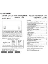
Lutron 697 User guide

Type
User guide

Lutron 697 is a lighting control device used with HomeWorks QS systems. It enables the control of Lutron EcoSystem digitally addressable fluorescent dimming ballasts and LED drivers. With a 2-wire non-polarized communication bus, it can control up to 128 EcoSystem drivers/ballasts with a maximum of 64 per EcoSystem link. The device supports grouping zones into a maximum of 64 zones per EcoSystem link and can be programmed using HomeWorks QS software. It also features auto-replacement for failed or replaced drivers/ballasts with its single-driver/ballast auto-replacement feature.

Lutron 697 is a lighting control device used with HomeWorks QS systems. It enables the control of Lutron EcoSystem digitally addressable fluorescent dimming ballasts and LED drivers. With a 2-wire non-polarized communication bus, it can control up to 128 EcoSystem drivers/ballasts with a maximum of 64 per EcoSystem link. The device supports grouping zones into a maximum of 64 zones per EcoSystem link and can be programmed using HomeWorks QS software. It also features auto-replacement for failed or replaced drivers/ballasts with its single-driver/ballast auto-replacement feature.

Using EcoSystem 1 Ballasts and Drivers in HomeWorks QS Systems
Application Note #697
Revision F
November 2021
1 www.lutron.com/support
Overview
Lighting fixtures that utilize Lutron EcoSystem digitally addressable fluorescent dimming ballasts and LED drivers can
be controlled in a HomeWorks QS system by using either DIN Rail Power Modules with EcoSystem (LQSE-2ECO-D)
or GRAFIKEye QS with EcoSystem (QSGRx-yE). Power Modules with EcoSystem are capable of controlling up to
128EcoSystem drivers / ballasts (64maximum per EcoSystem link). GRAFIK Eye QS with EcoSystem units are capable of
controlling up to 64 EcoSystem drivers / ballasts. Zones can be grouped together into zones either in the HomeWorksQS
software (for DIN rail power modules) or locally at the main unit (for GRAFIK Eye QS units). The DIN rail power modules
support up to 64 zones per EcoSystem link and the GRAFIK Eye QS units support up to 16 zones. EcoSystem
drivers / ballasts communicate over a 2-wire, non-polarized, topology-free, digital communication bus.
The purpose of this document is to explain how to design, program, activate, and troubleshoot a HomeWorks QS system
that utilizes EcoSystem drivers / ballasts. This document has two main sections: one focused on the Power Module with
EcoSystem solution and the other focused on the GRAFIK Eye QS with EcoSystem solution. Refer to the appropriate section
based on the control hardware being used in the application.
Note: Only HomeWorks QS software version 6.0.0 or later supports the use of Power Modules with EcoSystem and
GRAFIK Eye QS with EcoSystem.
Note: For optimal performance, Lutron recommends using HomeWorks QS software version 9.0.0 or later to program
EcoSystem devices. For more information, refer to Section 1.4.
Table of Contents
1.0 Power Module with EcoSystem ................................................................................................................. 2
1.1 Installation and Wiring ............................................................................................................................... 2
1.1.1 Wiring Tips ..................................................................................................................................... 2
1.1.2 Additional Notes ............................................................................................................................. 3
1.2 Adding and Configuring the Power Module in the Design Tab ...................................................................... 3
1.2.1 Creating EcoSystem Loads .............................................................................................................. 3
1.2.2 Adding Power Modules and Assigning Loads to EcoSystem Links ..................................................... 5
1.3 Activating the Power Modules and EcoSystem Drivers/Ballasts .................................................................... 6
1.3.1 Activate Power Modules .................................................................................................................. 6
1.3.2 Activate EcoSystem Drivers / Ballasts ............................................................................................... 6
1.4 Programming EcoSystem Zones in the HomeWorks QS Software............................................................... 10
1.4.1 Area Scene Programming Recommendations ................................................................................. 11
1.5 Replacing EcoSystem Modules ................................................................................................................ 12
2.0 GRAFIK Eye QS with EcoSystem ............................................................................................................ 13
2.1 Installation and Wiring ............................................................................................................................. 13
2.1.1 Wiring Tips ................................................................................................................................... 13
2.1.2 Additional Notes ........................................................................................................................... 13
2.2 Adding and Configuring the GRAFIK Eye QS with EcoSystem in the Design Tab ......................................... 14
2.3 Program and Activation Tabs ................................................................................................................... 15
Appendix A – Dimming Range of EcoSystem LED Drivers ......................................................................... 16
Lutron Contact Numbers ................................................................................................................................ 17
1 EcoSystem drivers are no longer available to order as of September 1, 2021.
2Customer Assistance — 1.844.LUTRON1
Application Note #697
1.0 Power Module with EcoSystem
The Power Module with EcoSystem is a QS wired device that resides on the QS link and counts as 1 device of the
available 99 devices on the link. Each module has 2 EcoSystem links and each EcoSystem link can have a maximum of
64EcoSystem drivers / ballasts that can be grouped together in up to 64 zones (128 maximum per module).
Below is a list of important technical documents pertaining to the Power Module with EcoSystem. Please review the
information contained within these documents as they will be referred to throughout this document.
Power Module with EcoSystem specification submittal (P/N 369611)
Power Module with EcoSystem install guide
DIN Panels and Accessories specification submittal (P/N 369788)
1.1 Installation and Wiring
Refer to the documents above for information regarding the installation and wiring of modules. See below for a system
example wiring diagram.
1.1.1 Wiring Tips
In addition to what is already called out in the Power Module with EcoSystem specification submittal and install guide, see
below for more EcoSystem wiring tips.
Do NOT connect line voltage to the 2-wire EcoSystem link
Do NOT connect the 2-wire EcoSystem link to earth ground. Connecting the EcoSystem link to earth ground will result in
fixtures flickering or being stuck at low-end.
EcoSystem wiring can be run in the same conduit as line voltage because it is treated as Class 1 wiring. Please follow all
Class 1 safety rules for EcoSystem wiring.
Any wiring topology (e.g., daisy-chain, star, home run, t-tap) can be used with EcoSystem wiring; however, for ease of
troubleshooting, Lutron recommends using daisy-chain wiring.
If using daisy-chain wiring for the EcoSystem link, Lutron recommends running a “loop back” wire from the last driver / ballast
on the link to the Power Module. Do not physically connect the wire to the Power Module. This “loop back” wire would only
be connected to the Power Module in the event of a wiring issue in the middle of the EcoSystem link.
Up to 64
drivers / ballasts
on each loop
QS Link
Eco Loop 1
Eco Loop 2
Driver
Driver
Power
Module
Power Module with
EcoSystem
HomeWorks QS
Processor
GRAFIK Eye
QS unit
QS
Contact
Closure
Interface
HomeWorks QS
Wallstation
Ballast
Ballast
120 / 230 V~
Control Power Up to 100 total
QS devices
QS
Power
Supply
Sivoia QS
Shade / Drapery
Continued on next page...
3www.lutron.com/support
Application Note #697
1.1 Installation and Wiring (continued)
1.1.2 Additional Notes
Each Power Module is 9 DIN modules wide and can be mounted in a 3rd party DIN rail panel or in a Lutron DIN rail Power
Module Enclosure.
Each Power Module counts as 1 device on the QS Link (PDU count = 0)
Each Power Module has 2 EcoSystem links and each EcoSystem link can control a maximum of 64 EcoSystem
drivers / ballasts.
Note: Lutron recommends not exceeding 63 drivers / ballasts on any given link. This is to take advantage of the single
driver / ballast auto-replacement feature. This feature automatically readdresses a new driver / ballast with the address of the
previous driver / ballast that failed or was replaced on the same link. This will work on any EcoSystem link with 63 or less
drivers / ballasts on the link. If more than 1 driver / ballast needs to be replaced, the new drivers / ballasts will need to activated
in the software. For more details on driver / ballast activation, see Section 1.3.
EcoSystem drivers / ballasts can be grouped together into lighting zones in the HomeWorks QS software. For more
information, see Section 1.2. A zone is a group of independently addressed drivers / ballasts which will operate and be
controlled as a single unit. Similar to traditional incandescent switch leg with multiple bulbs or fixtures on it.
Upon completion of the EcoSystem driver / ballast wiring, it is recommended to verify the wiring by using the “Test” button on
the Power Module. Refer to the Power Module with EcoSystem install guide for more information.
Use Area Scene programming. When multiple zones of EcoSystem controlled lighting is part of the same scene, it is best
to use HomeWorks QS software version 9.0 or newer to assign EcoSystem zones to the scene. This is accomplished by
using the Area Scene feature for the areas which contain the EcoSystem loads. In the Assignable Items drop-down menu,
these show up as Lighting – Areas instead of the more commonly used Lighting – Zones. Refer to Section 1.4 for more
information.
1.2 Adding and Configuring the Power Module in the Design Tab
1.2.1 Creating EcoSystem Loads
1. Click Design > Loads and verify that at least the columns listed below are visible. If not, click Customize Columns and
manually add them in.
a. Zone #
b. Zone Name
c. Load #
d. Fixture (required if using a Fixture Schedule)
e. Load Type (required if not using a Fixture Schedule)
f. Fixture Wattage
g. Fixture Qty
h. Emergency
Continued on next page...
4Customer Assistance — 1.844.LUTRON1
Application Note #697
1.2 Adding and Configuring the Power Module in the Design Tab (continued)
1.2.1 Creating EcoSystem Loads (continued)
2. Add the appropriate number of EcoSystem drivers / ballasts in a selected area by following the steps below.
a. Enter appropriate information in the Zone # and Zone Name fields (e.g., “1” and “Downlights” respectively). To group
multiple drivers / ballasts together in the same zone, modify the zone number of the selected driver / ballast to match the
drivers / ballasts already in the desired zone.
b. In the Load # field, enter the load number of each EcoSystem driver / ballast using the following format:
Power Module Panel #Power Module # in PanelEcoSystem Link #EcoSystem Address #
Example: The driver / ballast is connected to Panel 1, Power Module 1 in that panel, EcoSystem link 1 on the Power
Module, and the desired address for the driver / ballast is 1. The Load # would be “Power Module 1-1-1-1”. Using this
naming convention will help in the assignment, addressing, and troubleshooting process.
Note: For the address number, start with 1 and increase by 1 for each additional driver / ballast wired on the same
EcoSystem link. In order for the single ballast auto-replacement feature to work, do not exceed 63 drivers / ballasts on the
same link.
Note: On the ceiling plans, indicate the Load # of each EcoSystem fixture in the project to aid in the driver / ballast
addressing and activation process. Failure to do this will make driver / ballast addressing and troubleshooting very difficult.
c. If a Fixture Schedule was created in the project, assign the appropriate EcoSystem fixture to the load in the Fixture
field. Otherwise, set the Load Type column to an EcoSystem load type.
d. Enter the appropriate fixture wattage in the Fixture Wattage field and set the Fixture Qty field to “1” since each
EcoSystem driver / ballast needs its own unique address.
e. In the Emergency field, enter the emergency level for the fixture. The emergency level will trigger when the driver / ballast
is still receiving line voltage power but the EcoSystem link is disconnected or does not have power. EcoSystem
drivers / ballasts will go to their emergency level when one of the EcoSystem link wires is removed or the Power Module is
powered down which will remove power from the EcoSystem links.
3. Repeat step 2 for each additional EcoSystem driver / ballast. See below for an example of an area that contains
11EcoSystem drivers / ballasts and 3 lighting zones (Downlights, Sconces, Pendant).
Continued on next page...
5Customer Assistance — 1.844.LUTRON1
Application Note #697
1.2 Adding and Configuring the Power Module in the Design Tab (continued)
1.2.2 Adding Power Modules and Assigning Loads to EcoSystem Links
1. Navigate to design > equipment and add a “DIN Rail Power Module Eco” to the Toolbox. If the modules will be mounted in
Lutron DIN rail panels, add the panels to the Toolbox, too.
2. Add the appropriate number of Power Modules into the project and name them using the following format:
Power Module Panel #Power Module #
Example: 2 Power Modules mounted in Lutron DIN rail panels that house 2 Power Modules each (e.g., HQ-DP2). The first
module would be named “Power Module 1-1” and the second module “Power Module 1-2”.
3. Click on the Assign link in the Zone Name field for the Power Module that will have drivers / ballasts assigned to it. Assign
each driver / ballast to the appropriate EcoSystem link and address (1 64). See below for an example of drivers / ballasts
assigned to EcoSystem link 1. Notice how the Load # of each driver / ballast clearly defines the Panel #, Power Module #,
EcoSystem link #, and address.
4. After assigning all EcoSystem drivers / ballasts to the appropriate EcoSystem links, assign all Power Module to the QS link of
the processors on the design > Link Assignment screen. Remember that each Power Module counts as 1 of the available
99 devices on the QS link. Also, each zone of EcoSystem drivers / ballasts (not each driver / ballast individually) counts as 1 of
the available 512 zones on the QS link.
Continued on next page...
6www.lutron.com/support
Application Note #697
1.3 Activating the Power Modules and EcoSystem Drivers/Ballasts
1.3.1 Activate Power Modules
1. Navigate to activate > devices and select the processor QS links that the Power Modules are assigned to.
2. Activate the Power Modules on the QS links by either pressing and holding a button on each Power Module, manually
entering each Power Module serial number, or scanning each Power Module serial number. The Power Modules must be
activated before activating and addressing any EcoSystem drivers / ballasts.
1.3.2 Activate EcoSystem Drivers / Ballasts
1. Navigate to activate > drivers or activate > ballasts and select the EcoSystem link of the drivers / ballasts to be activated
from the Selected device loop drop-down menu.
2. After selecting the EcoSystem link to be activated, verify the wiring of all drivers / ballasts on the link by clicking High End,
Low-end, and Off. If any drivers / ballasts fail to respond as expected, correct the issue before proceeding.
Note: The EcoSystem link wiring can be tested at the Power Module by pressing the “Test” button on the unit. See
Section1.1 for more information.
Continued on next page...
7Customer Assistance — 1.844.LUTRON1
Application Note #697
1.3 Activating the Power Modules and EcoSystem Drivers/Ballasts (continued)
1.3.1 Activate Power Modules (continued)
3. Activate all new drivers / ballasts on the link. If an entire link of new drivers / ballasts are being activated for the first time,
select Activate all drivers / ballasts. If some of the drivers / ballasts on the link have already been addressed, select
Activate only new / unaddressed drivers / ballasts so that the drivers / ballasts that are already addressed do not get
unaddressed. Click Start Activation.
4. Verify that the number of drivers / ballasts detected on the link matches the number of drivers / ballasts assigned to that link in
the database.
5. Click Customize columns and click the box Show only unactivated drivers / ballasts. Notice how the last number in
each parentheses matches Address On Link. This will help in the addressing and troubleshooting process.
Continued on next page...
8www.lutron.com/support
Application Note #697
1.3 Activating the Power Modules and EcoSystem Drivers/Ballasts (continued)
1.3.1 Activate Power Modules (continued)
6. A random fixture on the link will begin to flash in order to identify itself. If there are multiple areas on the same EcoSystem
link (which is likely), it is easiest to address drivers / ballasts on an area by area basis rather than walking throughout the
residence trying to find the fixture that is flashing. To aid in this process, click Flash Next Driver / Ballast until a fixture in the
area to be activated starts to flash.
Example: Drivers / ballasts are being activated in the Great Room. Click Flash Next Driver / Ballast until a fixture in the
Great Room begins to flash. Using the ceiling plan with the load numbers of each EcoSystem fixture, identify the fixture that
is flashing and click Activate in the Action column for that fixture.
Note: If a flashing fixture is skipped before being activated, click Flash Previous Driver / Ballast to go back to that fixture.
7. After successfully activating a driver / ballast, the Status column will show Good and the Action column will show
Deactivate.
Continued on next page...
9Customer Assistance — 1.844.LUTRON1
Application Note #697
1.3 Activating the Power Modules and EcoSystem Drivers/Ballasts (continued)
1.3.1 Activate Power Modules (continued)
8. Repeat step 6 until all drivers / ballasts on the link have been successfully addressed and activated.
9. When all drivers / ballasts on a link have been addressed and activated, click Exit Activation to go back to the main
activation screen.
10. Verify that all drivers / ballasts were activated in the correct areas using the correct addresses. To do this, click Verify.
11. Click Start to begin the verification process. Once the verification process begins, the drivers / ballasts will flash one at a
time in the order that they are listed on the screen. The driver / ballast that is flashing will be highlighted in the grid. The grid
can be reordered by clicking the column headers. The verification process can be paused and resumed at any time.
12. Once all drivers / ballasts have been verified, click Exit.
13. Repeat steps 1 12 for all other EcoSystem links in the project.
10 www.lutron.com/support
Application Note #697
1.4 Programming EcoSystem Zones in the HomeWorks QS Software
EcoSystem zones can be programmed to any system trigger (e.g., keypad button, contact closure, timeclock event) or 3rd
party control similar to any other lighting zone.
Note: The HomeWorks QS software allows for a maximum fade time of 4 hours (14,400 seconds); however, EcoSystem
drivers / ballasts support a maximum fade time of 1 hour (3600 seconds). Any fade time for EcoSystem loads greater than
1hour will fade over the course of 1 hour.
For optimal performance, use HomeWorks QS software version 9.0 and newer with area scenes. area scenes are similar
to shared scenes but area scenes only applies to a single area of the area tree vs. shared scenes can span multiple
areas. Create area scenes by navigating to program > area scenes in the program tab drop down menu.
Each area has a default set of area scenes already created which adjusts all lighting zones in the area to common preset
levels (i.e., 100%, 75%, 50%, 25%, and 0%). These default presets can be renamed and re-programmed or new preset
scenes can be created in addition to the default presets. In the case of EcoSystem devices, presets would typically be
created and programmed to control only the EcoSystem devices within the space. Zones that are not to be affected by a
particular scene can be set to unaffected. When naming the preset, Lutron recommends naming it after the scene that it will
be assigned to (e.g., Goodnight, Welcome). Each area within the database can have 16 area scenes plus an off scene.
Once the area scenes have been defined, they can be assigned to the trigger by selecting Lighting – Areas under the
Assignable Items drop down menu.
Continued on next page...
11 Customer Assistance — 1.844.LUTRON1
Application Note #697
1.4 Programming EcoSystem Zones in the HomeWorks QS Software (continued)
1.4.1 Area Scene Programming Recommendations
Do not utilize different delays for zones within the same area. If a staggered or delayed on affect is desired, use standard
lighting zone programming to reduce transfer time. No warnings or pop-up messages will appear in the software because it
assumes that different delay times are intentional.
Raising the light level from off or lowering it to off may introduce a “popcorn” effect between zones even if area scenes have
been applied to the last button pressed. For applications with a lot of EcoSystem lighting, Lutron recommends disabling the
ability to raise from off and lower to off.
To disable the ability to raise from off and lower to off:
1. In the Tools drop down menu, select Project Settings.
2. Click the Programming tab and change Allow Lower to Off setting to Lower to Low-end. Lutron recommends only
doing this for Current Project Defaults so that only the current database is affected by this change.
3. Change Allow Raise From Off setting to Do Not Raise From Off. Lutron recommends only doing this for Current
Project Defaults so that only the current database is affected by this change.
Continued on next page...
12 www.lutron.com/support
Application Note #697
1.5 Replacing EcoSystem Modules
1. Navigate to Activate > Devices and select the processor QS link that the Power Modules are assigned to.
2. Find the Power Module that needs to be replaced and deactivate it.
3. Replace the Power Module and activate the new Power Module. See Section 1.3 for instructions.
4. Transfer the database with the new Power Module to the processors. At this point, the system will be up and running with
the new Power Module.
Note: For HomeWorks QS software versions older than 13.0, the drivers / ballasts will appear as unactivated until Activate
only new / unaddressed drivers / ballasts is selected.
Note: For HomeWorks QS software version 13.0 or newer, drivers / ballasts will show as activated once the new Power
Module is activated.
5. Click Start Activation and all the previously addressed drivers / ballasts will appear as activated.
Continued on next page...
13 Customer Assistance — 1.844.LUTRON1
Application Note #697
2.0 GRAFIK Eye QS with EcoSystem
GRAFIK Eye QS with EcoSystem units are available in a 6, 8, or 16 zone models. Zones 1, 2, and 3 on any GRAFIK Eye QS
with EcoSystem unit are integral line voltage dimming zones but can be configured to control EcoSystem lighting zones as
well. GRAFIK Eye QS with EcoSystem units can be used as either QS wired devices or as RF devices in the system.
Each GRAFIK Eye QS with EcoSystem unit can have a maximum of 64 EcoSystem drivers / ballasts connected to it using the
2-wire EcoSystem digital communication bus. EcoSystem drivers / ballasts can be grouped together into local zones at the
GRAFIK Eye QS with EcoSystem.
Below is a list of important technical documents pertaining to the GRAFIK Eye QS with EcoSystem unit. Please review the
information contained within these documents as they will be referred to throughout this document:
GRAFIK Eye QS with EcoSystem Specification Submittal
GRAFIK Eye QS with EcoSystem Installation and Operation Guide
2.1 Installation and Wiring
Refer to the documents above for information regarding the wiring, local addressing, and zone configuration of EcoSystem
drivers / ballasts connected to GRAFIK Eye QS with EcoSystem units. See below for a wiring example.
2.1.1 Wiring Tips
In addition to what is already called out in the EcoSystem documents, see below for more EcoSystem wiring tips.
Do NOT connect line voltage to the 2-wire EcoSystem link
Do NOT connect the 2-wire EcoSystem link to earth ground. Connecting the EcoSystem link to earth ground will result in
fixtures flickering or being stuck at low-end.
EcoSystem wiring can be run in the same conduit as line voltage because it is treated as Class 1 wiring. Please follow all
Class 1 safety rules for EcoSystem wiring.
Any wiring topology (e.g., daisy-chain, star, home run, t-tap) can be used with EcoSystem wiring; however, for ease of
troubleshooting, Lutron recommends using daisy-chain wiring.
If using daisy-chain wiring for the EcoSystem link, Lutron recommends running a “loop back” wire from the last driver / ballast
on the link to the Power Module. Do not physically connect the wire to the Power Module. This “loop back” wire would only
be connected to the Power Module in the event of a wiring issue in the middle of the EcoSystem link.
2.1.2 Additional Notes
Each GRAFIK Eye QS with EcoSystem unit counts as 1 device on the QS or RF Link (PDU count = 0).
Each GRAFIK Eye QS with EcoSystem unit has 1 EcoSystem link that can control a maximum of 64 EcoSystem
drivers / ballasts.
EcoSystem drivers / ballasts are grouped together into lighting zones at the GRAFIK Eye QS with EcoSystem unit. For more
information, refer to the EcoSystem Setup section of the GRAFIK Eye QS with EcoSystem Installation and Operation
Guide.
EcoSystem
Driver / Ballast
EcoSystem
Driver / Ballast
EcoSystem
Driver / Ballast
EcoSystem Bus
GRAFIK Eye QS with
EcoSystem
Up to
64drivers / ballasts
14 www.lutron.com/support
Application Note #697
2.2 Adding and Configuring the GRAFIK Eye QS with EcoSystem in the Design Tab
1. Navigate to design > controls and add a GRAFIK Eye QS with EcoSystem unit to the toolbox.
2. Navigate to design > loads and add the appropriate number of EcoSystem LED and / or fluorescent loads in each area.
Each GRAFIK Eye QS with EcoSystem unit can have a maximum of 64 EcoSystem drivers / ballasts connected to it and can
control a maximum of up to 16 zones. However, the Fixture Qty field is unable to be changed to anything other than 1 for
an EcoSystem load. For EcoSystem zones that contain multiple drivers / ballasts, leave the fixture quantity set to “1” and
enter the total fixture wattage in the Fixture Wattage field.
Example: 4 EcoSystem sconce fixtures that are 25 W each and in the same zone. Enter “100” in the Fixture Wattage field
and leave the Fixture Qty set to “1”.
Note: In the software it may appear that only 6, 8, or 16 ballasts are connected to the GRAFIK Eye QS with EcoSystem unit.
If there are multiple drivers / ballasts grouped into zones, each GRAFIK Eye QS with EcoSystem unit can not have more than
64 drivers / ballasts.
3. Add the appropriate number of GRAFIK Eye QS with EcoSystem units to each area on the design > controls screen and
assign each EcoSystem zone to the corresponding unit. The first 3 zones can be used as line voltage dimming zones or they
can be used to control EcoSystem drivers / ballasts.
15 Customer Assistance — 1.844.LUTRON1
Application Note #697
2.3 Program and Activation Tabs
EcoSystem drivers / ballasts can be programmed to any system triggers (e.g., keypad button, contact closure, timeclock
event) or 3rd party control like other load types.
Note: The programming suggestions for the Power Module with EcoSystem in Section 1.4 do not pertain to the GRAFIK
Eye QS with EcoSystem unit. The changes for EcoSystem programming in the HomeWorks QS software do not apply to
EcoSystem zones controlled by GRAFIK Eye QS with EcoSystem units.
Device activation of GRAFIK Eye QS with EcoSystem units can occur either before or after the EcoSystem drivers / ballasts
have been addressed and grouped into zones locally at the GRAFIK Eye QS with EcoSystem unit.
Note: All driver / ballast addressing and zoning is done locally at the GRAFIK Eye QS with EcoSystem unit, not in the
HomeWorks QS software. Refer to the GRAFIK Eye QS with EcoSystem Installation and Operation Guide for more
information on the wiring, local addressing, and zone configuration of the EcoSystem drivers / ballasts connected to each
GRAFIK Eye QS with EcoSystem unit.
16 Customer Assistance — 1.844.LUTRON1
Application Note #697
Appendix A – Dimming Range of EcoSystem LED Drivers
EcoSystem LED drivers support both a 1% and a more cost effective 5% low-end. Understanding low-end is critical to apply
LED lighting to areas of a residence. The 1% and 5% low-end values indicate that a fixture with one of those two options will
output 1% or 5% of its light intensity. Light intensity is defined as the luminance on a 1 ft2 (0.3 m2) surface of which there is a
uniformly distributed flux of one lumen. These percentages are measured using a light meter.
The most important aspect of understanding the dimming range is the difference between the low-end measured by a light
meter vs. the perceived low-end as observed by the human eye. The human eye is much more dynamic than a light meter
in that it can adjust to varying conditions within the environment. If the lights are dimmed to a low level, the human eye will
compensate by dilating the pupil to allow more light into the eye. The opposite is true at the brighter end of the range.
While a dimming range of 20 100% sounds like a large and satisfactory range, an understanding of measured vs. perceived
light will typically indicate that a 20% low-end will be inadequate in most lighting applications.
Measured Low-End Perceived Low-End
1% 10%
5% 22%
10% 32%
20% 45%
Home theaters, bedrooms, and dining rooms ideally require the ability to achieve a low-end of 1% or less; however, areas
like foyers, hallways, and stairwells may be fine utilizing 5% low-end. For most residential applications, low-end levels above
5% will likely produce an undesirable result because the eye will perceive the space to be brighter than what it actually is.
The chart below is a visual representation of the relationship between measured and perceived light levels across the entire
dimming range.
Perceived Light
0%
1%
5%
10%
20%
30%
40%
50%
60%
70%
80%
90%
100%
10% Light Management Dimming
5% High Perfomance Dimming
1% Architectural Dimming
22% 32% 60% 80% 90% 100%70%50%40%10%
Measured Light
Lutron Electronics Co., Inc.
7200 Suter Road
Coopersburg, PA 18036-1299 U.S.A.
P/N 048697 Rev. F 11/2021
Application Note #697
17
Lutron Contact Numbers
Lutron, HomeWorks, GRAFIK Eye, Sivoia, and EcoSystem are trademarks of Lutron Electronics Co., Inc., registered in the U.S. and other countries.
WORLD HEADQUARTERS
USA
Lutron Electronics Co., Inc.
7200 Suter Road
Coopersburg, PA 18036-1299
TEL: +1.610.282.3800
FAX: +1.610.282.1243
www.lutron.com/support
North & South America
Customer Assistance
USA, Canada, Caribbean:
1.844.LUTRON1 (1.844.588.7661)
Mexico:
+1.888.235.2910
Central/South America:
+1.610.282.6701
EUROPEAN HEADQUARTERS
United Kingdom
Lutron EA Limited
125 Finsbury Pavement
4th floor, London EC2A 1NQ
United Kingdom
TEL: +44.(0)20.7702.0657
FAX: +44.(0)20.7480.6899
FREEPHONE (UK): 0800.282.107
Technical Support: +44.(0)20.7680.4481
lutronlondon@lutron.com
ASIAN HEADQUARTERS
Singapore
Lutron GL Ltd.
390 Havelock Road
#07-04 King’s Centre
Singapore 169662
TEL: +65.6220.4666
FAX: +65.6220.4333
Technical Support: 800.120.4491
lutronsea@lutron.com
Asia Technical Hotlines
Northern China: 10.800.712.1536
Southern China: 10.800.120.1536
Hong Kong: 800.901.849
Indonesia: 001.803.011.3994
Japan: +81.3.5575.8411
Macau: 0800.401
Taiwan: 00.801.137.737
Thailand: 001.800.120.665853
Other Countries: +65.6220.4666
  • Page 1 1
  • Page 2 2
  • Page 3 3
  • Page 4 4
  • Page 5 5
  • Page 6 6
  • Page 7 7
  • Page 8 8
  • Page 9 9
  • Page 10 10
  • Page 11 11
  • Page 12 12
  • Page 13 13
  • Page 14 14
  • Page 15 15
  • Page 16 16
  • Page 17 17

Lutron 697 User guide

Type
User guide

Lutron 697 is a lighting control device used with HomeWorks QS systems. It enables the control of Lutron EcoSystem digitally addressable fluorescent dimming ballasts and LED drivers. With a 2-wire non-polarized communication bus, it can control up to 128 EcoSystem drivers/ballasts with a maximum of 64 per EcoSystem link. The device supports grouping zones into a maximum of 64 zones per EcoSystem link and can be programmed using HomeWorks QS software. It also features auto-replacement for failed or replaced drivers/ballasts with its single-driver/ballast auto-replacement feature.

Ask a question and I''ll find the answer in the document

Finding information in a document is now easier with AI