Page is loading ...

4-SeriesTM Low-Voltage Rough-In Enclosure
HWI-LV24-120
120 V , 50/60 Hz, 2 A
1
Please Read Before Installing
Installation Instructions
Overview
The 4 Series Low-voltage Rough-in Enclosure pro-
vides a compact housing for mounting the 4 Series
processor. The enclosure accepts one 120 V feed
to power the processor and its connected keypads.
The enclosure's main feed is self-contained in an
enclosed high-voltage area, eliminating exposure of
high voltage connections when the enclosure cover is
removed for low-voltage wiring. In addition to the
processor, up to 2 contact closure boards (HWI-CCO-
8 or HWI-CCI-8) and/or wire landing boards (HWI-
WLB) may be mounted in the 24 in. (70 cm) enclo-
sure. Contact closure outputs provide low-voltage con-
trol of motors and shades. Contact closure inputs
allow interfacing to photocells, security systems, and
other home systems. The wire landing board is a
wiring aid with three sets of four terminal blocks con-
nected pin-to-pin, simplifying home run wiring.
Important Notes
Codes: Install in accordance with all local and nation-
al electrical codes.
Note: Enclosure must be protected by an
appropriately rated (min. 15 A) circuit break-
er, to be supplied and installed in accordance
with local codes by the installer.
Mounting Location: Power supply will hum slightly
and internal relays will click while in use. Mount in a
location where such noise is acceptable.
Environment: Ambient operating temperature:
0-40°C, 32-104°F, 0-90% humidity, non-condensing.
Indoor use only.
Cleaning: To clean, wipe with a clean damp cloth.
DO NOT use any chemical cleaning solutions.
HWI-LV24-120
Knockout for
RS232 cable
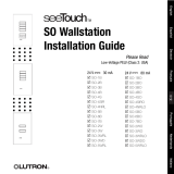
Mounting Diagram
24 in.
(61 cm)
15-1/8 in. (39 cm)
10-3/4 in.
(27 cm)
8 in.
(20 cm)
1-1/2 in.
(38 mm)
1-3/4 in.
(44 mm)
21-1/2 in.
(55 cm)
1-1/2 in.
(38 mm)
Screw
locations for
recess
mounting
5/16 in. dia.
(8 mm)
5/8 in. dia.
(16 mm)
keyholes
Mount
Enclosure
Vertically
Up

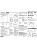
Wiring Diagram
Installation
1. Mount Enclosure using one of the following methods
(mounting hardware is not provided):
a. Surface Mount - Use keyholes shown in Mounting
Diagram (page 1)with bolts sufficient for 30 lbs. (14
kg) load (1/4 in. (M6) bolts recommended).
b. Recess Mount - Use screws sufficient for 30 lbs.
(14 kg) through the sides of the enclosure (see
Mounting Diagram, page 1). Mount enclosure flush to
or not more than 1/8 in. (3 mm) below the finished wall
surface. Enclosure is 3-7/8 in. (10 cm) deep past
cover mounting tabs. Enclosure cover dimensions are
24-1/2 in. x 15-7/8 in. (62 cm x 41 cm).
Danger - Locate and lock supply breaker in the
OFF position before connecting power input.
2. Remove high voltage cover and run power wiring
into the enclosure. Locations to run power wiring into
the enclosure are as shown in Wiring Diagram. Prepare
wires. When making wire connections, follow the recom-
mended strip lengths and combinations for the supplied
wire connectors. Note: Wire connectors provided are suit-
able for copper wire only.
Strip insulation 1/2 in. (10 mm) for 10 AWG
(6 mm
2
), 12 AWG (4 mm
2
) or 14 AWG (2.5 mm
2
).
Strip insulation 5/8 in. (16 mm) for 16 AWG
(1.5 mm
2
) or 18 AWG (1.0 mm
2
).
Use to join one or two 12 or 14 AWG supply wires
with one 10, 12, 14, 16 or 18 AWG control wire.
Connect Hot/Live feed to the black wire, Neutral feed to
the white wire, and Earth Ground to the green wire.
Replace high-voltage cover.
3. If the processor and the accessory boards are not to
be installed at this time, install the enclosure cover.
(Instructions for installing the processor and accessory
boards are supplied with the processor). Ensure product
identification label is at the bottom of the cover. Tighten
screws to 20 in.-lbs. (2.3 Nm).
Power wiring entry
(remove high-voltage
cover to access)
Low-voltage wiring
entry
Additional
Low-voltage wiring
entry
LIMITED WARRANTY
Lutron will, at its option, repair or replace any unit that is defective in materials or manufac-
ture within two years after purchase. For warranty service, return unit to place of purchase or
mail to Lutron at 7200 Suter Rd., Coopersburg, PA 18036-1299, postage pre-paid. Telephone
the Lutron Technical Support Center toll free at 800-523-9466. After the two year period, a
pro-rated warranty applies to this product until eight years after the purchase. For more infor-
mation regarding this warranty contact your Lutron representative.
THIS WARRANTY IS IN LIEU OF ALL OTHER EXPRESS WARRANTIES, AND THE
IMPLIED WARRANTY OF MERCHANTABILITY IS LIMITED TO TWO YEARS FROM PUR-
CHASE. THIS WARRANTY DOES NOT COVER THE COST OF INSTALLATION,
REMOVAL OR REINSTALLATION, OR DAMAGE RESULTING FROM MISUSE, ABUSE,
OR IMPROPER OR INCORRECT REPAIR, OR DAMAGE FROM IMPROPER WIRING OR
INSTALLATION. THIS WARRANTY DOES NOT COVER INCIDENTAL OR CONSEQUEN-
TIAL DAMAGES. LUTRON’S LIABILITY ON ANY CLAIM FOR DAMAGES ARISING OUT
OF OR IN CONNECTION WITH THE MANUFACTURE, SALE, INSTALLATION, DELIVERY,
OR USE OF THE UNIT SHALL NEVER EXCEED THE PURCHASE PRICE OF THE UNIT.
This warranty gives you specific legal rights, and you may also have other rights which vary
from state to state. Some states do not allow limitations on how long an implied warranty lasts,
so the above limitation may not apply to you. Some states do not allow the exclusion or limi-
tation of incidental or consequential damages, so the above limitation or exclusion may not
apply to you.
Lutron and HomeWorks are registered trademarks and 4 Series is a trademark of Lutron
Electronics Co., Inc.
© 2003 Lutron Electronics Co., Inc.
Technical and Sales Assistance
If you need assistance, call the toll-free Lutron
Technical Support Center. Please provide exact
model number when calling.
(800) 523-9466 (U.S.A., Canada and the Caribbean)
Other countries call:
Tel: (610) 282-3800
Fax: (610) 282-3090
Visit our Web site at www.lutron.com
Lutron Electronics Co., Inc.
7200 Suter Road
Coopersburg, PA 18036-1299
Made and printed in the U.S.A. 7/03 P/N 043-149 Rev. A 93-2605-04
High-voltage
section
No high-voltage in
shaded area
(Class 2 only)
/