Page is loading ...

R
Setup and Maintenance Guide
Dimming and
Switching
SS yy ss tt ee mm
LCP128
TM
LCP128
TM


R
LCP128
TM Setup and Maintenance Guide 3
Table of Contents
Page
Overview .........................................................................................................................................................14
STEP 1: Panel Configuration ..........................................................................................................................15
STEP 2: Time Clock Configuration ..................................................................................................................22
STEP 3: Scene Modification ............................................................................................................................27
STEP 4: Control Stations.................................................................................................................................29
STEP 5: Time Clock Events.............................................................................................................................36
STEP 6: Panel Contact Closure Inputs ............................................................................................................42
STEP 7: Emergency Power Mode ...................................................................................................................46
Page
Referenced Functions
Overrides...........................................................................................................................................49
Locking and Unlocking the Controller ................................................................................................53
Troubleshooting Guide
Troubleshooting Guide.......................................................................................................................55
Maintenance
Maintenance......................................................................................................................................60
Glossary of Terms
Glossary of Terms..............................................................................................................................61
Tables
Panel Tables ......................................................................................................................................62
Module Type Table.............................................................................................................................66
Load Type Table ................................................................................................................................67
Control Location Table.......................................................................................................................68
Control Station Table .........................................................................................................................69
Time Clock Event Table .....................................................................................................................71
Reference Information
Step-by-Step Programming Instructions
B
e
l
i
e
v
ei
t
o
r
n
o
t
,
t
h
i
s
i
s
s
u
p
p
o
s
e
d
t
o
l
o
o
k
l
i
k
e
a
d
i
c
t
i
o
n
a
r
y
!
T
h
i
s
i
c
o
n
w
a
s
c
r
e
a
t
e
d
b
y
B
r
e
n
t
M
.
N
y
e
,
J
u
l
y
6
,
1
9
9
5
.
B
e
l
i
e
v
e
i
t
o
r
n
o
t
,
t
h
i
s
i
s
s
u
p
p
o
s
e
d
t
o
l
o
o
k
l
i
k
e
a
d
i
c
t
i
o
n
a
r
y
!
T
h
i
s
i
c
on
w
a
s
c
r
e
a
t
e
d
b
y
B
r
e
n
t
M
.
N
y
e
,
J
u
l
y
6
,
1
9
9
5
,
u
n
d
e
r
t
h
e
d
i
r
e
c
t
i
o
n
o
f
D
e
r
e
k
R
.
T
h
o
m
a
s
.
T
h
i
s
i
c
o
n
w
a
s
c
r
e
a
t
e
d
b
y
B
r
e
n
t
M
.
N
y
e
,
J
u
l
y
6
,
1
9
9
5
.
B
e
l
i
e
v
e
i
t
o
r
n
o
t
,
t
h
i
s
i
s
s
u
p
p
o
s
e
d
t
o
l
o
o
k
l
i
k
e
a
d
i
c
t
i
o
n
a
r
y
!
T
h
i
s
i
c
on
w
a
s
c
r
e
a
t
e
d
b
y
B
r
e
n
t
M
.
N
y
e
,
J
u
l
y
6
,
1
9
9
5
.
B
e
l
i
e
v
ei
t
o
r
n
o
t
,
t
h
i
s
i
s
s
u
p
p
o
s
e
d
t
o
l
o
o
k
l
i
k
e
a
d
i
c
t
i
o
n
a
r
y
!
T
h
i
s
i
c
o
n
w
a
s
c
r
e
a
t
e
d
b
y
B
r
e
n
t
M
.
N
y
e
,
J
u
l
y
6
,
1
9
9
5
.
B
e
l
i
e
v
ei
t
o
r
n
o
t
,
t
h
i
s
i
s
s
u
p
p
o
s
e
d
t
o
l
o
o
k
l
i
k
e
a
d
i
c
t
i
o
n
a
r
y
!
T
h
i
s
i
c
on
w
a
s
c
r
e
a
t
e
d
b
y
B
r
e
n
t
M
.
N
y
e
,
J
u
l
y
6
,
1
9
9
5
.
u
n
d
e
r
t
h
e
d
i
r
e
c
t
i
o
n
o
f
D
e
r
e
k
R
.
T
h
o
m
a
s
.
T
h
i
s
i
c
o
n
w
a
s
c
r
e
a
t
e
d
b
y
B
r
e
n
t
M
.
N
y
e
,
J
u
l
y
6
,
1
9
9
5
.
B
e
l
i
e
v
ei
t
o
r
n
o
t
,
t
h
i
s
i
s
s
u
p
p
o
s
e
d
t
o
l
o
o
k
l
i
k
e
a
d
i
c
t
i
o
n
a
r
y
!
T
h
i
s
i
c
on
w
a
s
c
r
e
a
t
e
d
b
y
B
r
e
n
t
M
.
N
y
e
,
J
u
l
y
6
,
1
9
9
5
.
Page
How to Use this Guide .........................................................................................................................................4
System Specifications ...........................................................................................................................................5
System Start-Up Checklist.....................................................................................................................................7
Controller Overview ...............................................................................................................................................9
Introduction and System Startup

R
4 LCP128TM Setup and Maintenance Guide
Introduction
How to Use this Guide
This programming guide contains three main sections:
• Introduction - Includes system specifications, electrical contractor Start-Up Notice, and an overview of the
controller and how to use it.
• Step by Step Programming Instructions - Walks you through each step needed to program your system.
• Reference Information - Includes additional procedures that you may need to perform after the system is
programmed, including how to override system settings and lock/unlock the controller. This section also includes
troubleshooting tips, system maintenance, a glossary of terms, and system planning tables.
When programming the LCP128 system, you will need to know the following key information:
• How many panels are in this system and how many circuits are in each panel.
• How many modules are in the system and the module types.
• What the load schedule is.
• Where each wallstation and key switch is located and what each button or key turn should do.
• What each contact closure input and output should do.
• What the time clock should do.
Please read the guide completely before attempting to program the system.
Tables are provided at the back of this guide to record the above information. Photocopy the tables as
needed, and leave them for the occupant after they are completed.
Note: For mounting and wiring information, refer to the LCP128 Installation Guide, Lutron P/N 032-150.
LT-1
LT-1
Control Link 2000 ft. (600 m) maximum
LCP128 Panels
Control Stations:
Wallstations, key switches, contact
closure devices, and RS232 devices
System Overview Diagram

R
LCP128
TM Setup and Maintenance Guide 5
Introduction
System Specifications
LCP128 is a lighting control system designed for commercial buildings. It consists of up to 8 dimming panels
and up to 32 control stations. Control stations can be wallstations, key switches, contact closure input and
output devices (OMX-AV), contact closure output devices (OMX-CCO-8), or building management system
interfaces (OMX-RS232). All panels and control stations are connected by a digital communications link. Refer
to the LCP128 Installation Guide for wiring details. Other system specifications are described below.
Time Clock
• 7 weekly schedules.
• Up to 40 holiday schedules.
• Each holiday schedule can be 1-90 days.
• Up to 500 time clock events.
• Maximum of 25 time clock events per day.
• Up to 32 scenes and 1 Off scene.
• With each time clock event or control station input, you can select which circuits turn on or off and, for dimming
circuits, set specific dimming levels.
• Time clock events can occur at a fixed time of day or at a time relative to sunrise or sunset (astronomical).
• Events can be placed on either a weekly schedule (for example, occurring every Monday) or a holiday schedule
(for example, occurring only on January 1).
• Holiday schedules override weekly schedules.
• Time clock events can start and end afterhours mode. Afterhours is an energy saving mode where lights that
are set to be off will automatically, after a period of time, turn themselves off. Afterhours mode can be
temporarily overridden by any control station action. See STEP 5 for more information.
• Time clock events can enable and disable control stations.
Control Station - Wallstation
Wallstation buttons can be individually programmed to:
• Select a scene or custom scene. A scene is a combination of preset lighting levels used to automatically turn
on, off, or dim a circuit or group of circuits. Each time the wallstation button is pressed, the circuits go to the
programmed scene settings.
• Raise or lower circuits. Dimming circuits progressively raise or lower as long as the button is pressed. Circuits
stay at this setting until another event or control station input occurs.
• Toggle circuits on and off. Each press of the button alternates between turning the circuits on and off. If the
circuits are in a mixed state (some on and some off), the lights turn on.
• Turn off with a time delay. When the button is pressed, the circuits turn off after a preset amount of time.
• Enable or disable time clock.
Control Station - Key Switch
• The key switch (NTOMX-KS) can be programmed for clockwise and counterclockwise turns and with the same
functions as a wallstation button.
Control Station - Contact Closure Inputs
Two contact closure inputs are available on each LCP128 controller – more are available by purchasing a Lutron
OMX-AV control station (five inputs per OMX-AV that can be added anywhere on the digital control station link).
• The contact closure inputs can be programmed on the open and/or closure of the contact to perform the same
functions as a wallstation button.

R
6 LCP128
TM Setup and Maintenance Guide
Introduction
Control Station - Contact Closure Outputs
Contact closure outputs can be added with either a Lutron OMX-AV control station (five outputs per OMX-AV) or
with a Lutron OMX-CCO-8 (eight outputs per OMX-CCO-8). Either control station can be added anywhere on
the digital control station link.
• Each contact closure may be momentary or maintained.
• Each contact closure output can be assigned to an action that is programmed to a wallstation button, key turn,
contact closure input, timeclock event, or emergency state.
Integration through RS232
The LCP128 system can be integrated with a building management system through the Lutron RS232 interface
(OMX-RS232).
Emergency Power Mode
When a LCP128 panel is placed into emergency power mode (loss of normal power), circuits are changed to
emergency settings and remain at those settings until the controller exits emergency power mode (return of
normal power). All control station inputs and time clock events are ignored while in emergency power mode.
Emergency power mode can be activated using:
• Panel to panel emergency sense line. This method requires that the system have at least two panels. The
system must have at least one normal (non-essential) feed panel and at least one emergency (essential) feed
panel. When power to the normal panel is interrupted, the emergency panel(s) will go into emergency mode.
Note that the normal / emergency switches at the bottom of the controllers need to be set correctly.
• The Lutron emergency lighting interface (LUT-ELI-3PH), a UL 924 listed device, senses the normal (non-
essential) line voltage on all three phases (3PH) of normal power. When one or more phases of power are lost,
the LUT-ELI-3PH sends a signal to the LCP128 controller. If the LCP128 controller’s normal / emergency switch
is set to emergency, the emergency lighting scene or programmed circuit levels are activated.
For more information on emergency lighting applications, refer to Application Note #106. Available at
www.lutron.com.

LCP128 System Start-Up Checklist for Electrical Contractor
Important Note:
To ensure that the LCP128 System is ready for Start-Up, please complete the following checklist.
The LCP128 panel and control station(s) have been mounted in accordance with the installation instructions.
Control station(s) has been wired to the panel in accordance with installation instructions.
Feed and load wiring to panel have been installed in accordance with the installation instructions.
All load circuits have been activated in bypass mode (bypass jumpers installed) and are correctly and
permanently lamped.
Bypass jumpers have been removed and all circuits activated as default Non-Dim load type.
Load schedule for each panel has been completed.
Correct load type for each circuit has been determined and recorded.
When the above checklist is completed, please fax this sheet along with the completed load schedule
for each panel to Lutron Field Service Scheduling at (610) 282-0298.
Signature: ___________________________ Job Name: _________________________________________
Today’s Date: _________________________ Lutron Job Number: _________________________________
Printed Name: _______________________ Scheduled Startup Date: _____________________________
Phone Number: _______________________ Scheduled Startup Time: _____________________________
Fax Number: _________________________ Job Site Number: ___________________________________
Bill of Material (panels, control stations, etc.):
____________________________________ Qty. ___________
____________________________________ Qty. ___________
____________________________________ Qty. ___________
Lutron Electronics Co., Inc.
7200 Suter Road
Coopersburg, PA 18036-1299
Telephone: 800-523-9466 (Listen to menu for scheduling)
System Start-Up Checklist
R
LCP128
TM Setup and Maintenance Guide 7


R
LCP128
TM Setup and Maintenance Guide 9
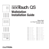
LCP128TM
LCP128 Controller Layout
Digital Control Station Link
and Emergency Sense Line
Connector
Panel Contact Closure
Inputs Connector
Digital Link Receive (RX) LED
Digital Link Transmit (TX) LED
24 VAC Power
Input Connector
Normal /
Emergency Switch
Module Control
Harness Connectors
Help Button
Home Button
Navigation Arrows
Right Soft Labeled
Button
LCD Screen
OK Button
Power OK LED
Controller Overview
Left Soft Labeled Button

R
10 LCP128
TM Setup and Maintenance Guide
Main Menu
Overrides
Time Clock Setup
Control Station Setup
Panel CCI Setup
Back
OK
Screen Title
Scroll Bar
Left Soft Label ( )
*
Right Soft Label ( )
Button Function
Navigate the screen and change highlighted values
Select an item
Left Soft-Labeled – Function defined on screen
Right Soft-Labeled – Function defined on screen
Go to the Home screen
On-Screen Help
?
*
OK
Navigation
The LCP128 controller uses certain methods for navigating, selecting, setting values, and so on. Please read
this section carefully before using the controller to program your system.
The LCP128 controller has nine buttons below the display. The table below explains their functions.
The Screen
All screens on the LCP128 controller have a
similar look with some common elements.
These are:
• A screen title
• Left and right soft button labels
• A scroll bar (only present if more information is
available than will fit on the screen.)
The example shows the Main Menu. The scroll
bar indicates that there is more information in the
menu than fits on the screen. Pressing
repeatedly scrolls through the menu and show
other choices. The shaded slider on the scroll
bar indicates what portion of the menu is being
displayed.
Help
Help on the current screen is always available by
pressing the button. If more information is
available than fits on the screen, use and
to scroll through the text. Pressing either ,
or returns you to the screen you were on.
*
OK
?
Help
The home screen shows the
current date and time. Press *
to go to the Menus, press # to go
to the Status screen.
Back
OK
Controller Overview

Main Menu
Overrides
Time Clock Setup
Control Station Setup
Panel CCI Setup
Back
OK
Getting to the Home Screen
Press from any screen to go back to the Home
screen.
Accessing the Main Menu
From the Home screen, press to go to the Main
Menu. If a password has been set, you need to
enter it before continuing (see “Locking and
Unlocking the Controller” in the reference section
later in this guide).
*
LCP128
TM
by Lutron
8:00 AM
Wednesday, Nov 3, 2004
Menu
Status
Press to Activate the Menu
*
Navigating the Menus
When in a menu, use and to change the
highlighted item and press or (OK) to select
that item. Pressing provides help on that item.
To go back to the previous screen, press (Back).
*
?
OK
Entering Data
One or more screens are used to program the
information required for each system feature.
If only one screen is required, the screen has the
soft labeled buttons “Cancel” and “Done”.
If multiple screens are required, the first screen has
the soft labeled buttons “Cancel” and “Next”.
Intermediate screens have the soft labeled buttons
“Previous” and “Next”, and the last screen has the
soft Labeled buttons “Previous” and “Done”.
Note: Data is not stored in the LCP128 system
database until “Done” is selected.
Afterhours Setup
Warn Time: min
Cancel
Next
Afterhours Setup
Flash Count: 0
Previous
Next
Afterhours Setup
Off Delay: min
Previous
Done
01
05
15
R
LCP128
TM Setup and Maintenance Guide 11
Controller Overview
(continued)

R
12 LCP128
TM Setup and Maintenance Guide
Getting Started - The Home
Screen
• When the controller is first powered or is not used
for 20 minutes, the display shows the Home
screen. Pressing (the Home button) always
takes you back to this screen. From the Home
screen, pressing displays the Main Menu and
pressing displays the Panel Status screen.
• The Home screen shows the current day, date and
time set on the controller. If either of these are
incorrect, refer to STEP 2 to set the date, time, and
location.
• The backlight on the LCD turns off after 25 minutes
of no activity. Pressing any button on the control
turns the backlight on and displays the Home
screen.
*
Unlocking the Controller
If the controller has been locked (see “Locking the
Controller” in the referenced function section) you
are prompted to enter the password before the
Main Menu is activated. Press and to select
the digit to change. Then press and to
change each digit. When you have entered the
password, press .
If you forget the password, contact Lutron technical
support at 1 (800) 523-9466 to unlock the
controller.
OK
LCP128
TM
by Lutron
8:00 AM
Wednesday, Nov 3, 2004
Menu
Status
Press to Activate the Menu
*
Unlock Panel
Enter Password
0 0 0 0
Cancel
OK
0
Controller Overview
(continued)
Language Select Screen
When the controller is first powered, you are
prompted to choose a language for the screens.
Use the navigation arrows to select a language,
then press or (Done).
OK
Choose Language
English
Francais
Espanol
Italiano
Done
Deutsch
Nederlands
Portugues

R
LCP128
TM Setup and Maintenance Guide 13
The Panel Status Screen
Pressing from the Home screen displays the
Panel Status screen. The Panel Status screen
shows:
• Your location.
• Sunrise and sunset times for the current system
date (note that the time, date, and location must be
configured correctly).
• Whether time clock events are enabled or disabled.
• Whether control stations are enabled or disabled.
Panel Status
Philadelphia, Pennsylvania
Today’s Sunrise: 05:59AM
Today’s Sunset: 6:07PM
Time Clock : Enabled
Back
Link Detail
The Wallstation Status Screen
Pressing from the Panel Status screen displays
the Wallstation Status screen. The Wallstation
Status screen shows:
• If the station is present and is recognized, the
control is labeled by its type (for example,
“seeTouch”).
• If a station is not present, it is labeled as “No
Station”. This could also indicate a control station
address conflict.
• If the unit is present and is not a control that is
known to the system, the control is labeled as
“???”. This could also indicate a control station
address conflict.
Wall Station Status
A01 - No Station
A02 - seeTouch
A03 - NT/KS/FOMX
A03 - ???
Back
OK
Controller Overview
(continued)

R
14 LCP128TM Setup and Maintenance Guide
Step by Step Programming Instructions
Overview
Programming your LCP128 system is done in seven steps.
1. Panel Configuration
This step selects a language for the controller LCD and configures the load setup. For multiple panel systems,
this step also assigns panel addresses and configures the number of circuits in each panel.
2. Time, Date, and Location
Required if the time clock will be used. This step shows how to set the clock.
3. Scene Modification
Required if changes are needed to the default scene settings.
4. Control Stations
Required if there is a remote wallstation, key switch, contact closure device, and/or RS232 device. This step is
performed to configure their function.
5. Time Clock Events
Required if the time clock will be used. This step is used to automatically dim or turn circuits on/off at either a
specific time of day or at a time relative to sunrise or sunset.
6. Panel Contact Closure Inputs
Required if the panel contact closure inputs are used. This step defines what each input will do.
7. Emergency Power Mode
Required if emergency lighting is needed when normal power is lost. Control station inputs and time clock
events are ignored while in emergency power mode. This step defines if the panel has emergency circuits and
how to configure the emergency lighting.
The following pages explain how to perform each of the programming steps.

R
LCP128
TM Setup and Maintenance Guide 15
Panel
Address 1
12
Circuits
System
Circuits
1-12
Panel
Address 2
24
Circuits
System
Circuits
13-36
Panel
Address 3
16
Circuits
System
Circuits
37-52
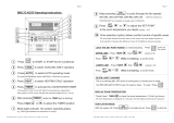
STEP 1
Panel Configuration
To program a LCP128 panel, you need to:
• Choose a language for the controller LCD.
• Set the panel configuration, including:
• Panel address
• First circuit number in the panel
• Number of circuits in the panel
Each circuit in the system is identified by a system circuit number. This number will be used to identify the
circuit for programming purposes. For example, if Panel 1 has 12 circuits, the first circuit in Panel 2 will be
circuit 13 on the LCP128 controller. The figure below shows a sample system.
Note: If your system has only one panel, you do not need to set the panel configuration. The panel address,
first system circuit number, and number of circuits are preprogrammed. However, for multi-panel systems,
you must set the panel configuration from the master panel (address 1) and then from each remote panel.
• Configure the load setup, including:
• Module type setup
• System size
• Load type
• High end trim
• Low end trim
All system programming (covered in programming STEPS 2-7) is performed at panel address 1. In a multi-
panel system, panel address 1 becomes the master programming panel and all other panels are remote panels.
Remote panels have limited menu options and functionality.
Before proceeding with STEP 1, complete the Panel, Module Type, Load Type, and Control Station
Tables located at the back of this guide.
Master Panel:
All system
programming
must take place
at this panel
First circuit in
this panel
First circuit in
this panel
First circuit in
this panel

R
16 LCP128TM Setup and Maintenance Guide
STEP 1 (continued)
Choose a Language
A. From the Main Menu use and to highlight
Panel Setup and press or (OK).
B. Use and to highlight Choose Language and
press or (OK).
C. Use and to set the Language and press or
(Done). The default is English.
OK
OK
OK
Panel Setup
Choose Language
Load Setup
Emergency Setup
Afterhours Setup
Back
OK
B.
Main Menu
Control Station Setup
Panel CCI Setup
Panel Setup
Scene Setup
Back
OK
A.
Choose Language
Cancel
Done
C.
Set System Size
You can set the system size so that controller
screens display only the circuits used by your
system. The default system size is 128 circuits.
A. From the Main Menu use and to highlight
Panel Setup and press or (OK).
B. Use and to highlight Load Setup and press
or (OK).
C. Use and to highlight System Size and press
or (OK).
D. Use and to set the total number of system
circuits and press or (Done).
OK
OK
OK
OK
System Size
How many circuits
are in this system?
Cancel
Done
52
D.
Load Setup
System Size
Chicago Setup
Low End Trim Setup
High End Trim Setup
Back
OK
C.
English
Francais
Espanol
Italiano
Deutsch
Nederlands
Portugues

R
LCP128
TM Setup and Maintenance Guide 17
STEP 1 (continued)
Set Panel Configuration -
Multi-Panel Systems Only
For multi-panel systems, you must set the address
and number of circuits for each panel, beginning
with the master panel.
A. From the Main Menu at the master panel
controller, use and to highlight Panel Setup
and press or (OK).
B. Use and to highlight Panel Addressing and
press or (OK).
C. Use and to set the Panel Address and press
or (Next).
Master panel address = 01
D. Use and to set the first system circuit number
in the panel, and press or (Next).
E. Use and to set the number of circuits in the
panel and press or (Done) to update the
database.
F. Repeat this procedure at each remote panel to set
the panel address and number of circuits.
Panel 2 address = 02
Panel 3 address = 03
Etc.
OK
OK
OK
OK
OK
Panel Setup
Panel Addressing
Load Setup
Emergency Setup
Afterhours Setup
Back
OK
Panel Addressing
Panel Address:
Master Programming Panel
Cancel
Next
01
B.
C.
Circuit Offset Setup
What is the first
system circuit number
in this panel?
Previous
Next
D.
001
Circuit Offset Setup
How many circuits
are in this panel?
Previous
Done
E.
36
Main Menu
Control Station Setup
Panel CCI Setup
Panel Setupetup
Scene Setup
Back
OK
A.

R
18 LCP128TM Setup and Maintenance Guide
STEP 1 (continued)
Module Type Setup
Your LCP128 system contains modules configured
with one or more outputs (circuits). The module
types are set by the model numbers of the panels
in the system. Complete the Module Type Table at
the back of this guide and then program the
module types for your system. The factory default
module type is X (4 Switches).
A. From the Main Menu use and to highlight
Panel Setup and press or (OK).
B. Use and to highlight Load Setup and press
or (OK).
C. Use and to highlight Module Type Setup and
press or (OK).
D. The Module Type Setup screen lists all the circuits.
To program a module, use and to select the
first circuit number in the module and and to
set the module type.
Module type options include:
X: Four-Circuit Switching (Relay) Module (XP)
S: One-output (circuit) Dimming Module (1U)
D: Two-output (circuit) Dimming Module (2U)
Q: Four-output (circuit) Dimming Module (4U)
E: Four-output (circuit) Electronic Low Voltage
Dimming Module (4E)
M: Four-output (circuit) Motor Module (4M)
F: Four-output (circuit) Quiet Fan Speed Module
(4FSQ)
Notes:
As you set each module type, the appropriate
circuit numbers are automatically assigned to the
module.
If you set the system size earlier in STEP 1, the
Module Type Setup screen lists only the circuits
used in your system.
E. When all the module types are set press or
(Done).
OK
OK
OK
OK
Load Setup
Module Type Setup
Chicago Setup
Low End Trim Setup
System Size
Back
OK
C.
Module Type Setup
001-004 - E:4 ELV
005-006 - D:2 dimmers
007-010 - X:4 switches
Cancel
Done
D.
011-014 - Q:4 dimmers
Panel Setup
Load Setup
Panel Addressing
Emergency Setup
Afterhours Setup
Back
OK
B.

R
LCP128
TM Setup and Maintenance Guide 19
STEP 1 (continued)
Load Type Setup
Complete the Load Type Table at the back of this
guide and then program the load types for your
system circuits. The factory default load type for
each circuit is Non-Dim.
Note: If you are unsure of the load type for a
particular circuit, set the load type to Non-Dim
until the correct setting is determined.
A. From the Main Menu use and to highlight
Panel Setup and press or (OK).
B. Use and to highlight Load Setup and press
or (OK).
C. Use and to highlight Load Type Setup and
press or (Next).
D. The Load Type Setup screen lists all the circuits.
For each circuit, use and to select the circuit
and and to select the load type.
Load type options depend on the module type
assigned to the circuit:
Switching: Non-dim, DSI, 0-10V, DALI, PWM
Dimming: Incandescent, MLV (Magnetic Low
Voltage), Tu-Wire (ballasts), Neon, ELV (Electronic
Low Voltage), Non-dim, DSI, 0-10V, DALI, PWM
Motors: Motor
Fans: Fan
E. When all the load types are set press or
(Done).
Load Type setup is now complete and all
settings are saved in the event of a power
failure.
OK
OK
OK
OK
Panel Setup
Load Setup
Panel Addressing
Emergency Setup
Afterhours Setup
Back
OK
B.
Load Setup
Load Type Setup
High End Trim Setup
Low End Trim Setup
Chicago Setup
Back
OK
C.
Load Type Setup
001 Dim - Incandescent
002 Dim - ELV
003 Relay - Non-Dim
Cancel
Done
D.
004 Dim - Tu-Wire
Caution! Failure to correctly assign load types
may damage loads–especially certain
electronic transformers, electronic ballasts,
and motors. Verify with the transformer or
ballast manufacturer that the product can be
dimmed with phase control dimming before
setting to any load type other than Non-Dim.

R
20 LCP128TM Setup and Maintenance Guide
STEP 1 (continued)
High/Low End Trim Setup
High and low end trim settings limit the maximum
and minimum output of a dimming circuit. Levels
are set automatically when the load type is
assigned. You should change the high or low end
trim for a circuit only if the default setting needs to
be adjusted.
A. From the Main Menu use and to highlight
Panel Setup and press or (OK).
B. Use and to highlight Load Setup and press
or (OK).
C. Use and to highlight High End Trim Setup or
Low End Trim Setup and press or (Next).
D. For each dimming circuit, use and to select
the circuit and and to set the trim level. Non-
dimming, motor, and fan circuits are set to NA (not
any).
E. When all the trim levels are set press or
(Done).
OK
OK
OK
OK
Load Setup
High End Trim Setup
Load Type Setup
Low End Trim Setup
Chicago Setup
Back
OK
C.
High End Trim Setup
001 Dim - 90%
002 Dim - 95%
003 Relay - NA
Cancel
Done
D.
All Circuits -
Caution! Do not reduce the low end trim on a
fluorescent load type. This will decrease lamp
life and may damage ballasts.
/