Page is loading ...

™
Innovative Prebuilt R/C Trainer Aircraft
• The video “Getting to the
Flying Field” makes mastering
Radio Control even easier –
watch it before getting started
• Builds with 2 tools in 1 evening
• We guarantee your success
Assembly Instructions
© Copyright 1998 HCAZ1176 for HCAA2200 V 1.0

2
We are so confident that the Hobbico AirVista is the best almost-ready-to-fly trainer
available that we make this guarantee: You will successfully learn how to fly with the
Hobbico AirVista or we will replace it with your choice of another Hobbico trainer of
up to equal value. All we ask is that you learn under the supervision of a qualified,
club-designated instructor, follow normal safety precautions, fly at an AMA-
chartered club and construct the kit as outlined in the included instruction manual.
If for some reason, you find the design and/or workmanship of the AirVista is not
conducive to learning to fly under the conditions outlined above, contact Hobby
Services, Monday through Friday, 9AM to 5PM central time to request a AirVista
replacement verification form. This form will verify that all
terms and conditions of the
flight guarantee have been followed and signatures
from you and your AMA-club
qualified instructor have been obtained.
This guarantee is effective for 60 days after you receive the kit and does not cover
incidental items (engines, radio equipment and hardware, etc.). The kit, along with
the replacement verification form and original purchase receipt must be returned to
Hobby Services for inspection no later than 60 days after receipt of the kit. Hobbico
reserves the right to verify all information provided. The AirVista Success Guarantee
is only good for kits purchased and flown in the United States. Replacement trainer
kit options are limited to flat-bottom wing
trainer models available from Hobbico and
only one replacement kit per customer.
Contact Hobby Services at:
Hobby Services
Attn: Service Department
1610 Interstate Drive
Champaign, IL 61821-1067
(217) 398-8970
SUCCESS GUARANTEE INFORMATION
™

3
Thank you for purchasing the prebuilt AirVista Trainer. You
have taken the first step into the exciting hobby of Radio
control. You are about to build in just one evening what took
aviation pioneers years – a powered machine that flies. The
AirVista was created especially for first time radio control
modelers. This easy to build, easy to fly model will help you
develop skills to take you anywhere you want to go in this
exciting hobby.
Please take some time to watch the video and read through
this assembly manual to familiarize yourself with the AirVista
kit and assembly methods.
Your AirVista is not a toy, but rather a sophisticated, working
model that functions very much like an actual airplane.
Because of its realistic performance, the AirVista, if not
assembled and operated correctly, could possibly cause injury
to yourself or spectators and damage property.
To make your R/C modeling experience totally enjoyable,
we
recommend that you get help from an experienced,
knowledgeable modeler for your first flights. You will learn
faster and avoid risking your model before you’re truly ready to
solo. Your local hobby shop has information about flying clubs
in you area whose membership includes qualified instructors.
You can also contact the national Academy of Model
Aeronautics (AMA), which has more than 2500 chartered
clubs across the country. Through any one of them, instructor
training programs and insured newcomer training are
available.
Contact the AMA at:
You only need two tools to build the AirVista:
❏ (1) Medium Phillips Screwdriver (#1)
❏ (1) Pliers
For convenience, these additional tools will make the job a
little easier:
❏ (1) Hobby knife with #11 blade
❏ (1) Adjustable wrench
❏ (1) Large Phillips Screwdriver (#2)
❏ (1) Scissors
❏ (1) Diagonal Cutter
❏ 4-channel radio system with 4 servos
❏ We recommend the Top Flite
®
Power Point
®
brand of props
(see the engine manufacturer’s recommendations)
❏ .40-size two-stroke engine
NO GLUE REQUIRED!
ACCESSORIES REQUIRED TO
FINISH YOUR AIRVISTA
OPTIONAL TOOLS
REQUIRED TOOLS
Academy of Model Aeronautics
5151 East Memorial Drive
Muncie, IN 47302
Office: (765) 287-1256
Toll Free: (800) 435-9262
Fax: (765) 741-0057
Web Site: http://www.modelaircraft.org
PROTECT YOUR MODEL, YOURSELF &
OTHERS...FOLLOW THESE IMPORTANT
SAFETY PRECAUTIONS
INTRODUCTION
0" 1" 2" 3" 4" 5" 6" 7"
0 10 20 30 40 50 60 70 80 90 100 110 120 130 140 150 160 170 180
Inch Scale
Metric Scale
O.S.
®
.40 LA
OSMG0040

4
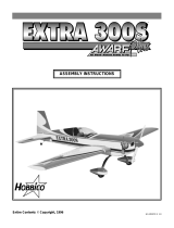
1 (1) Right Wing Panel
2 (1) Left Wing Panel
3 (1) Steel Wing Joiner Rod
4 (1) Plywood Center Rib Assembly
5 (1) Fuselage
6 (1) Fin/Rudder Assembly
7 (1) Stab/Elevator Assembly
8 (2) 4mm Landing Gear Wire
9 (1) 4mm Nose Gear Strut
10 (3) Wheels
11 (4) Plastic Dowel Caps
12 (2) Wing Dowels (Wood)
13 (1) Plywood Servo Tray
14 (1) 1.5mm Wire for Nose Gear Steering
15 (1) Spinner Assembly
16 (1) Steering Arm
17 (14) #64 Rubber Bands
18 (1) Foam Sheet
Hardware included with the kit:
(7) 3 x 5mm Screws
(1) 3 x 8mm Screw
(4) Nylon Torque Rod Horns
(4) Nylon Servo Connectors
(5) Nylon Clevis
(1) Fuel Tubing
(5) Clevis Retainer
(2) Brass Pushrod Connector
(2) Nylon Retainers For Brass Pushrod Connectors
(2) 2-56 Wire Pushrod for Elevator/Rudder
(2) 2-56 Wire Pushrod for Aileron
(1) 2-56 Wire Pushrod for Throttle
(1) Plywood Control Throw Gauge
(7) Metal Wheel Collars
(1) White Decal Strip
(1) Window Decal Sheet
(12) 2.5 x 10mm Sheet Metal Screws
(4) #4 x 5/8" Sheet Metal Screws
(2) 4-40 Lock Nuts
(1) #48 Drill Bit
(2) 4-40 x 1/8" Phillips Head Screw
(6) #4 Washers
(1) Fuel Tank Assembly
(2) Flat Landing Gear Straps
(4) 4 x 20mm Screws
(4) 4mm Washers
(4) 4mm Lock Washers
(4) 4mm Nuts
(1) Metal “T” Pin
(1) Video “Getting To The Flying Field”
(1) Small Rubber Band
(2) Metal Landing Gear Straps
Replacement Parts:
In the event that you need replacement parts, contact your hobby
dealer and ask for the following:
Right Wing Panel (HCAA3546)
Left Wing Panel (HCAA3548)
Aileron Servo Tray and Wing Joiner Rod (HCAA3550)
Fuse and Servo Tray (HCAA3552)
Tail Assembly (HCAA3554)
Landing Gear with Strap and Wheels (HCAA3556)
Cowl (HCAA3558)
Turtle Deck (HCAA3560)
1
2
5
9
3
4
11
12
17
13
18
11
14
10
15
15
16
6
7
8
AirVista Parts List
Take a moment to familiarize yourself with the parts of the AirVista.
If you need help or have any questions
during assembly, please contact us at:
(217) 398-8970
or e-mail us at
See more of our products at
www.hobbico.com
Need Help?
These items will not be
used in this kit:

5
Install the rubber grommets with brass
inserts to each of the four servos.
NNoottee::
Your system may look slightly
different. Consult your radio instructions.
CC..
Turn off your receiver switch followed by
the transmitter. Your servos are now
properly centered.
NNoottee::
If you bump or move your servos
during assembly, simply repeat this step.
SECTION 1
SECTION 1
Radio System Preparation
STEP 1: Unpack your Radio System
STEP 2: Connect your Radio System
BB..
Install the Brass Pushrod
Connectors onto
TTWWOO
of the arms.
CC..
Squeeze the nylon retainers in place
using your pliers.
AA..
From your radio system, select four
arms that look like an “X” or Star and
snap off the sides with your pliers.
(A diagonal cutter works well also).
STEP 3: Choose the Control Arms
AA..
Connect your radio
system and turn it on.
BB..
Position the “trim levers”
and sticks as shown.
ON
Throttle
Receiver
Battery
Servos
Transmitter
Switch
(Off)
Receiver
Brass Connector
Brass Connector (2)
4-40 Screw
4-40 Screw (2)
Nylon Retainer
Nylon Retainer (2)
Actual Size
Elevator
Enlarge
Enlarge
Enlarge
Tip! Hold the drill
bit with a pliers and
turn the arm.
Aileron
Rudder
Throttle
“X” Horn
Remove the wheels.
Charge your radio system following the
manufacturer’s instructions. This is usually
an overnight process.
Your grommets
may install like
one of these.
Throttle Trim
Star Horn
or
DD..
Enlarge the selected holes in the
servo arms using the drill
bit provided.

6
AA..
Connect the three servos to the receiver
according to the manufacturer’s instructions.
BB..
Connect the battery to the receiver switch
harness and the switch to the “battery”
socket on the receiver (the extra wire on the
switch is for charging your system).
CC..
Connect the extension
wire to the aileron socket.
STEP 5: Connect the Servos to the Receiver
Install the remaining
servo in the plywood
aileron servo tray. Note
the orientation and
routing of the
servo wire.
STEP 7: Install the Aileron Servo
STEP 6: Install the Receiver and Battery
AA..
Position the servos
where shown. Note
the orientation.
BB..
Using the screws
that came with
the radio system,
attach the servos
to the tray. Do not
overtighten.
CC..
Attach the servo
arms as shown in
the drawing.
STEP 4: Install the Servos
DD..
Tear or cut the foam
sheet in half and wrap
the receiver and the
receiver battery.
Use two #64 rubber
bands to secure the
receiver to the top and
the battery to the bottom
of the servo tray.
Elevator
Servo
Throttle
Servo
Plywood
Servo Tray
Receiver
Battery
Unwrap the
antenna wire.
Servo Tray
Aileron
Servo
Plywood Aileron
Servo Tray
Rudder
Servo

7
SECTION 2
SECTION 2
Wing Assembly
Assemble the wing together with the
steel rod and small alignment peg.
STEP 2: Assemble the Wing
Apply the white tape around
the center of the wing to hold
the assembly together.
STEP 3: Apply the Tape
Install the nylon torque rod
horns to the Ailerons, Rudder
and Elevator.
Use the “L” shaped plywood
gauge to set the height of the
horns, on each torque rod.
STEP 1: Install the FOUR Torque Rod Horns
Steel Rod
Wing Panel
The servo wire
should exit along the
edge of the servo
tray as shown.
Wing Panel
Alignment Peg
Nylon Torque Rod Horn (4)
Actual Size
1
2
4
AAiilleerroonn
Right Wing
(Upside Down)
Left Wing
(Upside Down)
RRuuddddeerr
Fin
EElleevvaattoorr
Horizontal
Stabilizer
Plywood
Aileron Tray
3

8
SECTION 3
SECTION 3
Fuselage Assembly
Tail and Wing Dowel Installation
Part
Part
The nylon horn
should be towards
the fuselage bottom.
Align the holes in the
fuselage with the holes
in the stab.
Insert the Stabilizer into the Fuselage.
STEP 1: Install the Horizontal Stabilizer
Insert the Fin into the fuselage. Use the
two 4-40 lock nuts along with washers
to hold the tail in place.
STEP 2: Install the Fin
STEP 3: Install the Wing Dowels
Fuselage Bottom
4-40 Lock Nut (2)
#4 Washer (2)
Actual Size
2.5 x 10mm Screw (4)
Actual Size
AA..
Install the
window decals.
B. Use the
screwdriver to
open the
dowel holes.
CC..
Insert the two
wood dowels
into the fuselage.
Install the Plastic
Dowel Caps.
You may need to hold one screw with a pliers
while installing the other side.
Note: Replace page 8 in
the Instruction Manual
with this page.

9
AA..
Insert the Black Nozzle into the Rubber “Stopper.”
BB..
Cut the fuel line to 2-3/4" (70mm) and install it onto the black nozzle and to
the Metal fuel pickup (commonly referred to as the “clunk”).
CC..
Insert the stopper into the tank and tighten the cap. You may need to
lubricate the stopper with skin oil (best found on the sides of your nose) to
help it install easier.
STEP 1: Assemble the Fuel Tank
Fuel Tank and Radio Tray Installation
Part
Part
T
T
wo
wo
CC..
Carefully install the fuel
tank into the fuselage
while pulling the tubing
from the front.
AA..
Insert the fuel tubing
into the holes located
on the firewall.
STEP 2: Install the Fuel Tank
Insert the two longest Pushrods into
the tubes from inside the fuselage.
The longer
of the two
pushrods
goes here.
If the pushrod guides are not pre-installed,
cut the pushrod guides approximately 1/2"
ahead of the bulkhead.
STEP 3: Insert the Pushrods
DD..
Slide the fuel tank in place. Make sure the fuel line
is not pinched during installation. This will cut off
the fuel supply to the engine.
BB..
Attach the tube that
goes through the left
hole to the black
nozzle. Attach the
tube that goes
through the right hole
to the top nozzle on
the tank.
NNoottee::
The
middle nozzle will
not be used.
Cut to 2-3/4” long.
Pushrod
Rubber Stopper
Cap
Black
Nozzle
Clunk
Actual Size
Fuel Line
NNoottee::
“Left” and
“Right” are as
viewed from the rear
of the airplane.

10
BB..
Secure it in place with four #4 x 5/8" screws
and washers.
CC.. NNoottee::
If you bump the servo arms, re-center
them as shown in section 1.
STEP 4: Install the Radio Tray
AA..
Insert the pushrods from the bottom of the servo arms
(for easier installation remove the arms from the servos).
BB..
Install the nylon pushrod retainers.
STEP 5: Hook Up the Servos
Nylon Pushrod Retainer (2)
AA..
Install the radio tray into
the fuselage.
#4 x 5/8” Screw (4)
#4 Washer (4)
Actual Size
Actual Size
Make sure the
servo wires do
not get pinched.
Cut the white
tubes if they are
in the way.

AA..
Install the two remaining clevises with retainers
onto the short pushrod wires.
BB..
Connect the rods using the nylon retainers.
CC..
Adjust the clevises so the ailerons are centered
when the servo is centered.
STEP 8: Install the Aileron Pushrods
CC..
Attach the switch to the
left side of the fuselage.
STEP 7: Attach the Switch
AA..
Slide a silicone clevis retainer onto each
wire pushrod. Attach the clevises onto
the threads using the tool provided.
BB..
Make sure the servos do not move.
CC..
Screw the clevises on so that the control
surfaces are centered. Attach the clevises
to the horns.
DD..
Slide the retainers over the
clevises.
STEP 6: Attach the Clevises to the Control Surfaces
Nylon Clevis (2)
Silicone Clevis
Retainer
Nylon Clevis
Silicone Clevis
Retainer
Silicone Clevis
Retainer
Clevis Tool
Antenna Wire
Actual Size
Retainer
Silicone Clevis
Retainer (2)
11
AA..
Position a nylon
strap on
the
antenna wire about
6" away from the
receiver. This is
called “strain
relief.”
BB..
Route the antenna
wire through the
longer slot where
you installed
the switch.
Nylon Strap (1)
Actual Size

12
AA..
Insert the steering pushrod wire through the outer hole in
the nylon steering arm. Slide the wire into the tube so
that it will extend through the brass connector on the
rudder servo.
BB..
Place a 4mm metal collar over the nose gear strut. Slide
the strut in place capturing the steering arm between the
bottom bracket and engine mount.
CC..
Tighten the steering arm screw so the end of the steering
arm is positioned about 3/8" (10mm) from the firewall while
the nose gear is straight.
DD..
From the inside fuselage, tighten the screw to secure the
pushrod to the brass connector.
STEP 1: Install the Steering Hardware
Landing Gear Installation
Part
Part
AA..
Insert the two main landing
gear wires into the slots on the
bottom of the fuselage.
BB..
Secure the landing gear using
two metal straps and four
2.5 x 10mm screws.
CC..
Attach the wheels using the
4mm metal collars with the
3 x 5mm screws.
STEP 2: Install the Main Landing Gear and Wheels
4mm Metal Collar (1)
4mm Metal Collar (6)
3 x 5mm Screw (1)
3 x 5mm Screw (6)
2.5 x 10mm Screw (4)
Metal Strap (2)
3 x 8mm Screw (1)
3 x 8mm Screw
Nylon Steering
Arm
Metal Collar
2.5 x 10mm Screw
3 x 5mm
Screw
3 x 5mm
Screw
Pushrod
Tube
Nose Gear
Strut
3 x 5mm Screw
Pushrod
Use drill bit to
enlarge the
outside hole.
Actual Size
Actual Size
Actual Size
IMPORTANT! Check and
retighten the engine
mount screws.

13
AA..
Attach a clevis with retainer onto the remaining
pushrod wire.
BB..
Insert the wire into the fuselage so that it passes
through the brass connector on the throttle servo.
STEP 2: Install the Throttle Control Linkage
Place the engine onto the engine
mount. Use the plywood gauge
to set the distance from the
firewall. The engine should be
positioned straight or slightly to
the right (NEVER LEFT).
Cut the fuel tubing
so that each tube
sticks out about 6".
Engine Installation
Part
Part
Four
Four
STEP 1: Install the Engine
CC..
Attach the clevis to the
throttle arm and slide the
retainer in place.
4 x 20mm Screw (4)
4 x 20mm Screws
Tip! If installing an O.S.
®
40
LA engine, install the back
two screws with plates first.
Next, slide the engine into
position and install the
front screws. This is because
access is restricted due to
the remote needle valve.
4mm Nut (4)
4mm Nuts
Brass Connector
Carburetor arm
4mm Split Washer (4)
4mm Split Washers
Mounting Plates
Distance Gauge
Position the
engine straight
or slightly right.
Actual Size
Nylon Clevis (1)
Cut the pushrod
tube off to
approximately 1/8"
from the firewall.
Silicone Clevis
Retainer (1)
Actual Size

14
AA..
Position the cowl so the thrust
washer on the engine sticks out
1/8" (3mm). Make sure the
spinner does not contact the
cowl at any point.
STEP 4: Attach the Cowl and Install the Spinner
Attach the fuel tube that
comes out of the “left” hole in
the firewall, to the nozzle on
the carburetor.
Attach the remaining fuel
tubing to the muffler. This is
called the “vent line” or
“muffler pressure line.”
STEP 5: Attach the Fuel Lines
Note: For some
engines, you may
need to trim the
cowl to provide
access to the
needle valve.
BB..
At the holes in the cowl, use
the four 2.5 x 10mm screws to
attach the cowl in place.
If there is a lot of
extra tubing, you
may cut off some of
the excess.
STEP 3: Position the Cowl, Install the Muffler
Work the cowl around the
engine. Install the muffler.
TTIIPP!!!!!!
Position the prop so it is horizontal when you can feel
compression. (This way, if your engine quits in flight, the prop will
stop horizontal, therefore reducing the chance of prop breakage
due to a hard landing.)
Make sure the
prop is tight!
Muffler Pressure tap
To Carburetor
2.5 x 10mm Screw (4)
Thrust
Washer
Actual Size

15
STEP 2: Apply the Decals
STEP 3: Attach the Wing
BB..
Thread the second nylon strap near the end
of the antenna wire. Tie the small rubber
band to the strap.
STEP 1: Attach the Antenna to the Fin
Final Assembly
Part
Part
Five
Five
CC..
Place the rubber band over the pin
head and adjust the strap so there is a
slight amount of tension on the
antenna wire.
AA..
Insert the T- Pin into
the top of the fin just in
front of the plastic tip.
Nylon Strap (1)
Longer
Slot
Strain
Relief
4
4
2
2
IImmppoorrttaanntt!!
Plug the aileron servo wire into
the receiver.
Attach the wing to the Fuselage using twelve
#64 rubber bands. Attach four on each side
and criss-cross the remaining four.
Actual Size
Apply the stripes to the cowl sides.
Wrap the excess inside the back part
of the cowl.
Reinstall the screws.
Temporarily remove the bottom cowl screws.

16
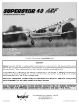
Note: We recommend that you have your instructor help you
with the set up of your radio system.
CHECK THE CONTROL DIRECTIONS
1. Turn on the transmitter and then the receiver. Standing
behind the plane, make the following movements with the
transmitter and observe the control surfaces:
If any of the servo movements are wrong, reverse the servo
direction with the servo reversing switches on the
transmitter.
ADJUST THE THROTTLE
2. For added safety and convenience, the throttle should be
set up so that the engine can be stopped using the throttle
trim. To do this, loosen the pushrod connector screw and move
the throttle pushrod so that the carburetor is completely
closed with the throttle stick and trim lever on the transmitter
fully back. (Note: If the carburetor does not fully close, adjust
the idle stop screw on the carburetor until it will.) Next, tighten
the screw on the pushrod connector. Test the trim lever by
advancing it to full. This will be a fast idle position with the
carburetor barrel open slightly (about 1/32" or .8mm).
Now move the throttle stick forward to full. Make sure that the
carburetor barrel opens all the way. (See sketch.) If it doesn't
open far enough or opens too far (bending the rod) move the
pushrod connector in or out on the servo arm and/or the
carburetor arm to gain or reduce movement. The throw will be
correct when the carburetor barrel will stop fully open at the
same time the throttle stick reaches full. With the throttle set
up properly, you should be able to run the engine with the trim
lever set midway to the full position (adjusted for a smooth but
slow idle). Then when it is time to stop the engine, simply pull
back on the trim to close the carburetor and the engine will
stop running.
ADJUST THE NOSE WHEEL
3. With the radio system on, adjust the steering pushrod at the
rudder servo, so that the nose wheel is straight. Tighten the
screw on the brass connector.
ADJUST THE CONTROL THROWS
4. Check the movement of the control surfaces. Use a ruler to
match our measurements listed below. If your radio features
dual rates, set up both the high and low rates following the
radio system's instructions. If your radio does not have dual
rates, set up the plane using low rates first and increase the
throws as you get familiar with the plane.
Low Rate High Rate
Aileron 1/2" (13mm) up 5/8" (16mm) up
1/2" (13mm) down 5/8" (16mm) down
Elevator 3/8" (10mm) up 1/2" (13mm) up
3/8" (10mm) down 1/2" (13mm) down
Rudder 1" (25mm) left Same as low rate
1" (25mm) right Same as low rate
These are the suggested deflections from center.
4-CHANNEL
TRANSMITTER
4-CHANNEL
TRANSMITTER
4-CHANNEL
TRANSMITTER
4-CHANNEL RADIO SET-UP
(STANDARD MODE 2)
TRANSMITTER
4-CHANNEL
ELEVATOR MOVES UP
RIGHT AILERON MOVES UP
LEFT AILERON MOVES DOWN
RUDDER MOVES RIGHT
FRONT WHEEL MOVES RIGHT
CARBURETOR WIDE OPEN
RADIO SYSTEM SET-UP
Open Slightly (Idle)
Barrel Fully Open
SECTION 4
SECTION 4
Preparing For Flight

17
If you need more control movement, you can move the nylon
horn closer to the control surface or you can move the rod at
the servo away from the center of the servo horn. If you have
too much movement, reverse the process.
One leading cause of crashes is flying an airplane with its
control throws set differently from those recommended in the
instructions. The Great Planes AccuThrow
™
lets you quickly
and easily measure actual throws first, so you can make
necessary corrections before you fly. Large, no-slip rubber feet
provide a firm grip on covered surfaces without denting or
marring the finish. Spring tension holds AccuThrow’s plastic
ruler steady by each control surface. Curved to match control
motions, the ruler provides exact readings in both standard or
metric measurements. GPMR2405.
CHECK THE LATERAL BALANCE
Now that you have the model completed, this is a good time to
balance the airplane laterally (side-to-side). Here is how to
do it:
❏ 1. Attach the wing to the fuselage.
❏2. With the airplane sitting level, lift the model by the engine
propeller shaft and the bottom of the fuselage at the tail (this
may require two people). Do this several times.
❏ 3. If one wing always drops when you lift the model, it
means that side is heavy. Balance the airplane by attaching
weight to the lighter wing tip. Note: An airplane that has been
laterally balanced will track better in loops and other
maneuvers. Balancing weight is available from your local
hobby dealer.
CHECK THE FORE-AFT BALANCE (CENTER OF GRAVITY)
Note: This section is VERY important and must NOT be
omitted! A model that is not properly balanced will be unstable
and possibly unflyable.
❏ 1. Accurately mark the balance point on the bottom of the
wing on both sides of the fuselage. The balance point is
located 3-3/8” (85mm) back from the leading edge. This is the
balance point at which your model should balance for your first
flights. Later, you may wish to experiment by shifting the
balance up to 1/4" (6mm) forward or back to change the flying
characteristics. Moving the balance forward may improve the
smoothness and arrow-like tracking, but it may then require
more speed for takeoff and make it more difficult to slow down
for landing. Moving the balance aft makes the model more
agile with a lighter and snappier “feel”. In any case, please
start at the location we recommend and do not at any time
balance your model outside the recommended range.
❏ 2. With the wing attached to the fuselage, all parts of the
model installed (ready to fly), and an empty fuel tank, position
your fingertips at the marked balance point.
❏ 3. Lift the model. If the tail drops when you lift, the model is
“tail heavy” and you must add weight* to the nose. If the nose
drops, it is “nose heavy” and you must add weight* to the tail
to balance.
Note: Nose weight may be easily installed by using a Heavy
Spinner Hub or gluing lead weights to the firewall. Tail weight
may be added by using Great Planes (GPMQ4485) “stick-on”
lead weights.
*If possible, first attempt to balance the model by changing the
position of the receiver battery and receiver. If you are unable
to obtain good balance by doing so, then it will be necessary
to add lead weights to the nose or tail to achieve the proper
balance point.
CG
3-3/8"
(85mm)
BALANCE YOUR MODEL
IMPORTANT!

18
Improve the flight of your AirVista with the Great Planes C.G.
Machine’s exact balancing. The C.G. Machine’s stable,
“hands-off” operation eliminates the potential for error. It works
with all airplanes weighing up to 40 pounds–regardless
of size or
wingspan. GPMR2400.
If you are a novice, there is one thing that you will need to fly
your AirVista safely that is not furnished with the kit: You will
need a qualified instructor to teach you how to fly. No model
ever made will let you teach yourself to fly safely. It can be
done, but you would be seriously risking more than just the
airplane. To find an instructor, you should join an R/C flying
club. If there is not a club nearby, then you should find an
experienced model pilot who is willing to help you. The chosen
instructor should fly well enough to allow you to concentrate on
your own flying. If you are worried about your instructor
crashing your model, you will not be able to concentrate on
learning to fly. After you have found an instructor, you should
spend some time just talking about what you will be trying to
learn. They should inspect the model to be certain that it is
ready to fly. Listen to them and learn from their experience.
Now that you have a good model and an instructor that you
can trust, you can go out and start learning to fly. You can
expect to be very nervous at first, and will make some
mistakes. There will be several instances where the instructor
will prevent you from crashing. This will be unsettling, but the
thing to do is jump right back into flying the model (after your
knees stop shaking, of course). This is one of the most
important things about learning to fly model airplanes...you
have to fly! Fly as often as you can. Be sure to make several
flights each time you go to the flying field, but give yourself
time after each flight to calm down and discuss the flight with
your instructor. Spending some time after each flight talking
about what happened and what you need to work on to
improve your skills will pay off with greater confidence in your
own growing abilities.
CHARGE THE BATTERIES
Follow the battery charging procedures in your radio
instruction manual. You should always charge your transmitter
and receiver batteries the night before you go flying, and at
other times as recommended by the radio manufacturer.
BALANCE THE PROPELLER
Balance your propellers carefully before flying. An unbalanced
prop is the single most significant cause of damaging
vibration. Not only will engine mounting screws and bolts
vibrate out, possibly with disastrous effect, but vibration will
also damage your radio receiver and battery. Vibration may
cause your fuel to foam, which will, in turn, cause your engine
to run rough or quit.
We use a Top Flite
®
Precision Magnetic Prop Balancer
(#TOPQ5700) in the workshop and keep a Great Planes
®
Fingertip Balancer (#GPMQ5000) in our flight box.
FIND A SAFE PLACE TO FLY
The best place to fly your R/C model is an AMA (Academy of
Model Aeronautics) chartered club field. Ask your hobby shop
dealer if there is such a club in your area and join. Club fields
are set up for R/C flying and that makes your outing safer and
more enjoyable. The AMA also can tell you the name of a club
in your area. We recommend that you join the AMA and a local
club so you can have a safe place to fly and have insurance to
cover you in case of a flying accident. (The AMA address is
listed on page 3 of this instruction book).
If a club and its flying site are not available, you need to find a
large, grassy area at least 6 miles away from any other R/C
radio operation like R/C boats and R/C cars and away from
houses, buildings and streets. A schoolyard may look inviting
but it is too close to people, power lines and possible radio
interference.
GROUND CHECK THE MODEL
If you are not thoroughly familiar with the operation of R/C
models, ask an experienced modeler to check to see that you
have the radio installed correctly and that all the control
surfaces do what they are supposed to. The engine operation
also must be checked and the engine “broken-in” on the
ground by running the engine for at least two tanks of fuel.
Follow the engine manufacturer’s recommendations for break-
in. Check to make sure all screws remain tight, that the hinges
are secure and that the prop is on tight.
PREPARING TO FLY YOUR AIRVISTA

19
RANGE CHECK YOUR RADIO
Check the operation of the radio before each time you fly. First,
make sure no one else is on your frequency (channel). With
the transmitter antenna collapsed and the receiver and
transmitter on, you should be able to walk at least 100 feet
away from the model and still have control. Have someone
help you. Have them stand by your model and, while you work
the controls, tell you what the models various control surfaces
are doing.
Repeat this test with the engine running at various speeds with
an assistant holding the model. If the control surfaces are not
always acting correctly, do not fly! Find and correct the
problem first.
ENGINE SAFETY PRECAUTIONS
Note: Failure to follow these safety precautions may result in
severe injury to yourself and others.
Keep all engine fuel in a safe place, away from high heat,
sparks or flames, as fuel is very flammable. Do not smoke
near the engine or fuel; and remember that the engine exhaust
gives off a great deal of deadly carbon monoxide. Therefore do
not run the engine in a closed room or garage.
Get help from an experienced pilot when learning to operate
engines.
Check the engine bolts occasionally and retighten.
Use safety glasses when starting or running engines.
Do not run the engine in an area of loose gravel or sand, as
the propeller may throw such material in your face or eyes.
Keep your face and body as well as all spectators away from
the rotation of the propeller as you start and run the engine.
Keep items such as these away from the prop: loose clothing,
shirt sleeves, ties, scarfs, long hair or loose objects (pencils,
screwdrivers) that may fall out of shirt or jacket pockets into
the prop.
Use a “safety stick” device or electric starter; follow
instructions supplied with the starter or stick. Make certain the
glow plug clip or connector is secure so that it will not pop off
or otherwise get into the running propeller.
Make all engine adjustments from behind the rotating
propeller. IMPORTANT: Never reach around a rotating
propeller.
The engine gets hot! Do not touch it during or after operation.
Make sure fuel lines are in good condition so fuel will not leak
onto a hot engine.
To stop the engine, cut off the fuel supply by closing off the fuel
line or follow the engine manufacturer’s recommendations. Do
not use hands, fingers or any body part to try to stop the
engine. Do not throw anything into the propeller of a
running engine.
Read and abide by the following Academy of Model
Aeronautics Official Safety Code:
GENERAL
1. I will not fly my model aircraft in sanctioned events, air
shows, or model flying demonstrations until it has been proven
to be airworthy by having been previously successfully flight
tested.
2. I will not fly my model aircraft higher than approximately 400
feet within 3 miles of an airport without notifying the airport
operator. I will give right of way to, and avoid flying in the
proximity of, full scale aircraft. Where necessary an observer
shall be used to supervise flying to avoid having models fly in
the proximity of full scale aircraft.
3. Where established, I will abide by the safety rules for the
flying site I use, and I will not willfully and deliberately fly my
models in a careless, reckless and/or dangerous manner.
7. I will not fly my model unless it is identified with my name
and address or AMA number, on or in the model.
9. I will not operate models with pyrotechnics (any device that
explodes, burns, or propels a projectile of any kind).
RADIO CONTROL
1. I will have completed a successful radio equipment ground
check before the first flight of a new or repaired model.
2. I will not fly my model aircraft in the presence of spectators
until I become a qualified flier, unless assisted by an
experienced helper.
3. I will perform my initial turn after takeoff away from the pit or
spectator areas, and I will not thereafter fly over pit or
spectator areas, unless beyond my control.
4. I will operate my model using only radio control frequencies
currently allowed by the Federal Communications
Commission (FCC).
The moment of truth has finally arrived. You’ve put a lot of
effort into building your model and it looks great! Protect your
investment by following a few simple tips:
1. If possible, have an experienced modeler look over your
work before you head out to your flying field. It’s easier to fix
problems in the workshop instead of the flight line.
FLYING YOUR AIRVISTA
AMA SAFETY CODE (excerpt)

20
2. Become familiar with starting your engine, and break it in
before going for your first flight. Be sure the engine will stop
when the trim lever is pulled all the way back.
3. Assemble a simple flight kit (a shoe box is fine to start with)
which should include a starting battery and glo-plug clip
(or ni-starter), “chicken stick” for flipping the prop, fuel and a
means of filling the
tank, a couple of small screwdrivers, #64
rubber bands,
spare prop and glo-plug, 6” adjustable wrench,
and a pair of needle nose pliers. In addition to tools, you
should also take along some paper towels and spray window
cleaner to remove fuel residue after each flight.
4. When you load up to go to the flying field be sure that the
batteries have charged for at least 14 hours, and that you have
your fuselage, wing, transmitter, and flight box. And, most
important, you have your AMA license.
5. Range check the radio! See page 19.
USING RUBBER BANDS
The rule of thumb is to use two #64 rubber bands per pound
of model weight. If your model weighs in at 6 pounds, you
need 12 rubber bands. It doesn’t matter too much how many
you run straight across the wing or how many are criss-
crossed, so long as the last two are criss-crossed. This trick
stops the other bands from popping off. Do not use oily rubber
bands for more than a few flying sessions. Check each rubber
band before using it; discard any that have cracks. Rubber
bands can be conditioned by storing the oily ones in a zip-top
storage bag partially filled with talcum powder or corn starch.
Both products will absorb the oil.
TAXIING
Start the engine and set the throttle trim for a slow, steady idle.
Have your instructor or a helper hold the plane while you work
the controls. Upon release, advance the throttle slightly to start
rolling, then back-off the power to prevent going too fast and
possibly taking off. Stand behind the plane as it taxies away
from you and note the direction it turns as you move the rudder
control. One thing to keep in mind with R/C models (whether it
be cars, boats, or planes) is that the steering controls may
seem to “reverse” when the model is moving toward you. For
example, if you are flying toward yourself, and you give a right
control input (ailerons or rudder), the model will move off to
your left. The fact of the matter is of course, that the controls
are not reversed and the aircraft did actually enter a right turn.
The plane does move off to your left from your vantage point,
but if you imagined yourself in the cockpit you would realize
the plane turned to the right as commanded. All it takes is a
little practice to maintain proper orientation of your aircraft, but
that’s why we recommend finding an instructor.
When you feel comfortable, advance the throttle a little while
standing behind the plane to get the feel of a takeoff roll, but
pull back on the power before the model lifts off. Try this
several times, adding a little more power each time. If the
plane starts to veer off, immediately cut the power to prevent
a mishap.
Although many R/C pilots have taught themselves to fly, we
strongly recommend that you find an instructor to help get you
started. Although trainer airplanes offer the greatest
opportunity of success for the self-taught, there is a high
probability that you will crash your airplane on the first flight.
Protect your investment of time and money—obtain the
assistance of an experienced R/C pilot.
TAKEOFF
Your first flights should be made in little or no wind. If you have
dual rates on your transmitter, set the switches to “low rate” for
takeoff. Taxi into position, pointing directly into the wind.
Although this model has good low speed characteristics, you
should always build up as much speed as your runway will
permit before lifting off, as this will give you a safety margin in
case of a “flame-out.” Advance the throttle smoothly to the
wide-open setting. When the plane has sufficient flying speed
(you won’t know until you try), lift off by smoothly applying a
little up elevator (don’t force it off into a steep climb!), and
climb out gradually, trying to keep it straight and the wings
level. Climb to about 100 feet before starting a VERY gentle
turn by moving the aileron stick. Apply a little more back
pressure on the elevator stick as the model turns. Stop the turn
by moving the aileron stick in the opposite direction until the
wings are level, then return the stick to the neutral position.
Pull the power back to 1/2 throttle.
FLYING
We recommend that you take it easy with your model for the
first several flights and gradually “get acquainted” with the
plane as your engine becomes fully broken-in. Trainers are
designed to fly level with neutral elevator trim at approximately
1/3 - 1/2 throttle — this is the best speed for learning to fly. On
later flights, if you want your model to maintain level flight at
full throttle, you will need to give it a little down trim.
Your first flights should consist of mostly straight and level
flight with gentle turns to keep the model over the field. These
flights will give you practice at coordinating your control inputs
and maintaining the proper orientation of the airplane. As
mentioned earlier, turns are accomplished by banking the
aircraft with the ailerons (rudder will accomplish this on a
3-channel airplane) then gently adding some back stick (up
elevator). Enough back stick should be held in to keep the
aircraft at a constant altitude. To stop turning, apply opposite
aileron (or rudder) to level the wings, then release the sticks.
There is a memory aid that may help keep you out of trouble
when the plane is flying toward you — “put the stick under the
low wing.” In other words, move the stick in the direction of the
low wing to raise that wing. When you are comfortable flying
the aircraft, you can practice using the rudder along with the
ailerons to “coordinate” the turns — usually, a small amount of
rudder applied in the direction of the turn will keep the tail
following in the exact same track as the nose.
The most common mistake when learning to fly is “over
control.” Think of pressure instead of large movements of the
control sticks. Remember, most trainers will recover from
almost any over control situation (given enough altitude) if you
simply let go of the sticks.
/