Page is loading ...

Entire Contents © Copyright, 1996
HCAZ3078 V 1.0
™
ASSEMBLY INSTRUCTIONS

Take a moment now to
match the box contents
with the items listed
below. Following the
Extra 300S assembly
instructions will be
quite easy if you
identify and organize
the parts before you
begin. You may also
want to review the
glossary of special
modeling terms that
starts on page 33 of
this manual. Words in
your instructions that
appear in bold italic
type are explained in
this section.
Replacement Parts Available
HCAA3621...Wing Kit HCAA3625....Wheel Pants Set
HCAA3622...Fuselage Kit HCAA3626....Canopy
HCAA3623...Cowl Set HCAA3627....Spinner
HCAA3624...Fin Set HCAA3628....Landing Gear Set
2
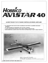
Landing Gear
Part # Quantity
15 Main landing gear .....................2
5 Tail gear wire.............................1
4 Tail wheel ..................................1
14 Main wheels..............................2
13 Wheel pants..............................4
48 4 x 18mm bolts..........................2
49 3 x 10mm sheet metal screws..2
50 Axles .........................................2
51 3mm nuts ..................................6
Wing Assembly
Part # Quantity
6 Wing fairing..............................................1
7 Right wing panel......................................1
8 Left wing panel.........................................1
28 *Clevises..................................................2
39 Fiberglass tape........................................1
40 4mm washers ..........................................2
41 4 x 35mm bolt..........................................2
42 4mm O-ring..............................................2
43 Plywood front plate..................................1
44 Plywood rear plate...................................1
45 Servo tray supports..................................2
46 Servo tray ................................................1
47 *Aileron control horns ..............................2
51
40
42
43
44
47
46
45
39
49
48
50
You’re about to build in just days what took aviation
pioneers years—a powered machine that flies. Specially
created for you and other experienced radio control
modelers, Hobbico’s Extra 300S offers nearly all the
excitement of piloting a real airplane...and develops skills
that will take you anywhere you want in your hobby.
41
*Parts marked with an asterisk are found on the plastic parts tree.
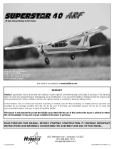
Know Your Model’s Parts
Tail Assembly
Part # Quantity
1 Stabilizer and elevator...................1
16 Rudder and fin ..............................1
28 *Clevises.......................................5
29 *Control horns...............................2
30 Pushrods.......................................2
31 2mm x 18 mm machine screws....4
48 Elevator splitter plate ....................1
30
28
48
31
29
28

Engine Mounting Parts
Part # Quantity
11 Engine mount ....................................2
32 4 x 18mm bolts..................................4
33 4mm washers....................................4
34 4 x 25mm bolts..................................4
35 4mm lock washers.............................4
36 4mm nuts...........................................4
37 Pushrod tube.....................................1
38 Pushrod wire......................................1
Fuse Parts
Part # Quantity
2 Canopy ..............................................1
3 Aft tail cover.......................................1
9 Cowl top.............................................1
10 Cowl bottom.......................................1
12 Spinner ..............................................1
17 Servo tray..........................................1
18 Servo tray former...............................1
27 Fuselage............................................1
Fuel Tank & Parts
Part # Quantity
19 Fuel tank ............................................1
20 Rubber tank stopper ..........................1
21 Fuel pick-up weight (clunk)................1
22 Plastic stopper compression disks
(one large and one small)..................2
23 Aluminum fuel tubing
(one short and one long)....................2
24 3 x 18mm screw.................................1
25 Silicone fuel line.................................1
26 Foam tank collar ................................1
3
18
17
23
21
25
24
20
22
38
26
6
7
19
17
18
11
12
9
27
14
14
15
13
16
8
10
1
2
* Engine mounting parts may differ from those shown in the photo.
3
5
4
Nylon
Hardware
35
33
34
Parts shown smaller than actual size (out of proportion).
37
32
36

Getting Ready for Flight
Your Hobbico Extra 300S is ready for takeoff in as little as 20 hours. Your hobby
dealer or flying instructor (see next page) can help you decide what accessories
you’ll need for flight. Most are one-time only purchases—and your instructor will
probably allow you to use his field box until you can outfit your own with a glow
plug starter, fuel pump and “chicken stick" or electric starter. You will need to
provide your own fuel. Use glow fuel with a 10-15% nitro blend to keep your
engine performing at its peak...and your Extra 300S will have the power to make
you an accomplished pilot!
Other Items You’ll Need:
Glues
Choose 6-minute and 30-minute epoxy, such as Great Planes
Pro
TM
Epoxy, which has been formulated especially for R/C
model building. Pro Epoxies offer a strong bond and a variety
of curing times suited for every step of assembly. You’ll also
need a thin instant-setting CA (cyanoacrylate), a thicker CA+,
plus rubbing alcohol for easy epoxy cleanup.
Model Engine
Power your Extra 300S with any high-quality,
.60-size model engine. The O.S. .60 FP, or
SuperTigre S-61K are fine engines for this plane.
Look for features such as easy break-in, easy
starting, efficient carburetion and low maintenance.
Check the manufacturer’s recommendations for
propellers to use with your engine.
Radio Equipment
To let you send the commands that control your Extra
300S’s “flight path,” you’ll need a 4-channel aircraft radio
system with four standard servos. Many 4-channel
radios include just three servos. You may need to
purchase the fourth separately. The servos and radio
receiver will be mounted on-board your model and need
to be cushioned from jolts and vibration. One-half inch
thick foam rubber sheets (HCAQ1050) are available for
this purpose
.
Hardware
Tools and accessories required for
assembly include a hobby knife; small and
large Phillips screwdrivers; needle nose
pliers; drill with 1/16", 1/8", 3/32" 3/16",
5/32" and 17/64" bits; ruler; #64 rubber
bands; 1 foot of medium fuel tubing;
petroleum jelly; and 400-grit sandpaper.
Other General Items Required
Epoxy Brushes (GPMR8062) Mixing Sticks (GPMR8055) Clothespins Foam Rubber (HCAQ1050)
T-Pins (HCAR5150) Masking Tape String Felt-Tip Pen
Sanding Block Adjustable Wrench Paper Towels Builders Triangle Set (HCAR0480)
Plastic Wrap or Wax Paper Round Toothpicks Bondo Filler Wire Cutter
70% Isopropyl Alcohol Small Hobby Clamps Razor Saw Thread Locking Compound
4

T
he best way to begin flying your
Extra 300S is with an experienced
R/C pilot or flying instructor at your
side. You’ll learn faster, and avoid
risking your model before you’re
truly ready to solo.
Where do you find an instructor?
Ask at your local hobby shop.
They’ll have information about
flying clubs in your area whose
membership includes qualified
instructors. You should also join the
Academy of Model Aeronautics
(AMA), a 165,000 member-strong
national organization with more
than 2,300 chartered clubs across
the country. Through any one of
them, instructor training programs
are available. Contact the AMA at
the address or phone number
below:
Academy of Model Aeronautics
5151 East Memorial Drive
Muncie, IN 47302
Office: (317) 287-1256
Toll Free: (800) 435-9262
Fax: (317) 741-0057
Find a Flying Instructor
WARNING! This is not a Toy! Please follow these safety precautions:
90-Day Limited Warranty
If you, as the original owner of this model, discover defects in parts or
workmanship within 90 days of purchase, Hobbico will repair or replace it –
at
the option of our authorized U.S. repair facility, Hobby Services – without
charge. Our liability does not include cost of shipping to us. However, Hobby
Services will pay shipping expenses to return your model to you.
You must provide proof of purchase, such as your original purchase invoice
or receipt, for your model’s warranty to be honored.
This warranty does not apply to damage or defects caused by misuse or
improper assembly, service or shipment. Modifications, alterations or repair
by anyone other than Hobby Services voids this warranty. We are sorry, but
we cannot be responsible for crash damage and/or resulting loss of kits,
engines, accessories, etc.
Repair Service
Your Extra 300S must be returned directly to Hobby Services for warranty
work. The address is:
Hobby Services, Attn: Service Department, 1610 Interstate Drive,
Champaign, IL 61821-1067 Phone: (217) 398-0007.
Please follow the instructions below when returning your model. This will
help our experienced technicians to repair and return it as quickly
as possible.
1. ALWAYS return your entire system, including airplane and radio.
2. Disconnect the receiver battery switch harness and make sure that the
transmitter is turned off. Disconnect all batteries and drain all fuel.
3. Include a list of all items returned and a THOROUGH, written explanation
of the problem and service needed. If you expect the repair to be covered
under warranty, also include your proof of purchase.
4. Include your full return address and a phone number where you can be
reached during the day.
If your model is past the 90-day warranty period or is excluded from
warranty coverage, you can still receive repair service through Hobby
Services at a nominal cost. Repair charges and postage may be prepaid or
billed COD. Additional postage charges will be applied for non-warranty
returns. All repairs shipped outside the United States must be prepaid in
U.S. funds only.
All pictures, descriptions and specifications found in this instruction manual
and on the product package are subject to change without notice. Hobbico
maintains no responsibility for inadvertent errors.
Before you fly:
1.Make sure that no other fliers are using your radio
frequency.
2.Your radio transmitter must be the FIRST thing you
turn ON, and the LAST thing you turn OFF.
3.Double check all control surfaces.
4.Make sure that the transmitter & receiver batteries
are fully charged.
Fuel storage and care:
1.Do not smoke near your engine or fuel.
2.Store all engine fuel in a safe, cool, dry place, away
from children and pets. Model fuel will evaporate, so
make sure that you always store it with the
cap secure.
When starting and running your engine:
1.Always wear safety glasses.
2.Make certain that your glow plug clip is securely
attached to the glow plug and cannot pop off,
possibly falling into the spinning propeller.
3.Use a “chicken stick” or electric starter to start the
engine – NOT your fingers.
4.Make sure that the wires from your starter and glow
plug clip cannot become tangled with the spinning
propeller.
5.Do not stand at the side of the propeller when you
start or run the engine. Even at idle speed, the
spinning propeller will be nearly invisible.
6.If any engine adjustments are necessary, approach
the engine only from behind the spinning propeller.
5
JOIN THE AMA

6
General Inspection
❏ Remove the fuselage, wing panels, rudder assembly
and stabilizer assembly from their bags. Inspect all
items closely to check for any damage. If any damage
is found, contact the the place your Extra was
purchased, or Hobby Services to obtain replacement for
your damaged items. Also check for any covering that
may have came loose. If any is found, it can be
reattached using Medium CA glue.
Prepare the Wing Panels:
❏ Mark the ailerons using masking tape, then remove
them from the wing panels and set them aside. This
marking process is done to insure the proper ailerons
can be returned to its respective panel when the
ailerons are reattached.
Test Fit the Wing Panels:
❏ The wing panels in the Extra 300S are joined
upside down. The top of the wing must be flat on your
work surface to obtain the proper dihedral angle. Test fit
the panels together to make sure there is no gap
between the panels. If any gap exists, use a flat sanding
block or similar tool to sand the wing roots to achieve
a perfect fit between the panels.
Join the Wing Panels:
❏ After putting down a piece of plastic to protect your
work surface, mix up 3/4 oz.of 30-minute epoxy and
liberally coat the root of each panel. Securely tape the
panels together, making sure that the leading edges of
the wing are lined up with each other. The rear of the
wing can be held in alignment using clamps and mixing
sticks. Clean up any excess epoxy that may remain
using a paper towel and 70% Isopropyl Alcohol. Use
books or some other form of weight to hold the wing
panels flat against the work surface while the epoxy dries.
Flat Building Surface
Bottom of the Wing
Wing Assembly

Prepare the Servo Box Plates:
❏ Locate the 2-3/8" x 1-3/8" x 1/16" plywood front
plate and the 2-3/8" x 1-1/4" x 1/16" plywood rear
plate. Also locate the two 2-1/8" x 7/16" x 1/16" servo
tray supports. Draw a line on both the front and rear
plywood plates, 7/16" from the top. Using Medium CA,
glue the servo tray supports into position.
Note: Before mixing any epoxy, perform a trial run of
this step to make sure that all parts fit securely. The
servo tray in this step will hold the front and rear plates
in position while the epoxy dries.
Construct the Aileron Servo Box:
❏ Coat the entire inside of the servo box using
30-minute epoxy. Install the front and rear plates with
the servo tray supports towards the top of the wing.
Apply a small amount of epoxy to the servo tray
supports and install the aileron servo tray.
Reinforcing the Wing Center Section:
❏ Lightly sand the center section of the wing to
remove any excess epoxy and smooth the center
section for the application of the Fiberglass Cloth.
Starting on the bottom of the wing, cut a piece of the
2-3/4" fiberglass so that it is 1/16" shorter than the chord
of the wing. Mix up 3/4oz. of 30-Minute epoxy. Using an
epoxy brush, apply a coat of epoxy to the wing center
section. Lay the fiberglass cloth down, and gently
squeegee the cloth so the epoxy comes through the
cloth. Use the squeegee to help spread the epoxy over
the cloth. Clean up any excess epoxy that may have
gotten onto the covering of the wing using a paper towel
and 70% Isopropyl Alcohol.
❏ After the epoxy has fully cured, repeat this process
for the top of the wing. Fiberglass the area in front of the
servo box separately from the rearward area. Trim any
fiberglass that may protrude from the wing edges using
a hobby knife.
Attach the Wing Front Former:
❏ Lightly sand the front of the wing to remove any
excess epoxy and to even up the front of the wing.
Attach the wing front former using 30-Minute epoxy.
The wing front former is properly aligned when the top
edge of the former is even with the top edge of the wing.
Use masking tape to hold the former in position until the
epoxy has fully cured.
7

8
Install Wing Alignment Dowels:
❏ Using a 17/64" drill bit, drill two holes into the front of
the wing using the wing front former as a guide. Drill
these holes 1-3/4" deep. After test fitting the dowels into
the holes, glue the wing dowels into place. Make sure
to leave 1/2" of the dowel exposed to fit into the fuselage.
Install Aileron Tray Doublers:
❏ Cut two mixing sticks to fit into the openings of the
servo box as shown. Glue them into position using
Medium
CA.
Install Servo Tray Doublers:
❏ Using Medium CA, glue two mixing sticks to the
servo tray as shown. Do not let the sticks overlap into
the openings for the servo or the sides of the servo tray.
❏ Using Medium CA, install the servo tray and servo
tray former into position. Note that the doublers are on
the underside of the servo tray.
Locate the Wing Bolt Mount:
❏ Locate the three wing bolt plates – they should be
numbered. If the numbering can’t be read, use the
photo to distinguish the differences between the plates
and number them accordingly.
Fuse Assembly

Laminate the Wing Bolt Mounts:
❏ Apply 30-minute epoxy to one side of each the #1
and #3 wing bolt mounts. Stack the mounts in numerical
order – 1, 2, 3. Align the holes in the mounts and use
either clamps or clothespins to hold the mounts together
and in alignment until the epoxy has cured.
Install the Blind Nuts:
❏ Clean up the holes in the wing bolt mounts using a
3/16" drill bit. Install the blind nuts into mount plate #3
by gently tapping them into place using a hammer.
Apply a small amount of Medium CA to the blind nuts to
hold them into position. Be careful not to get any CAinto
the threaded area of the nuts.
Note: Perform the next two steps with the same
batch of epoxy.
Install the Wing Bolt Mount:
❏ Test fit the wing bolt mount into the fuselage, with the
blind nut on the inside of the fuselage. Light sanding
may be required to achieve a snug fit of the mount.
Once a good fit has been achieved, glue it into position
using 30-minute epoxy.
Install the Tail Mounting Block:
❏ With the excess epoxy, glue the tail mounting block
into position at the rear of the fuselage.
Fitting the Wing to the Fuselage:
❏ Clean up the holes for the wing dowels in the
fuselage using a 17/64" drill bit.
Attach the Wing to the Fuselage
9

❏ Test fit the wing into position. The wing may need
slight sanding to fit around the fuselage. If so, remove
only a small amount of material at a time until the wing
fits into position. Make sure to apply a thin coat of Thin
CA to the exposed wood so that fuel won’t damage the
wood over time.
Aligning the Wing:
❏ Place a T-pin in the center of the tail mounting block
at the rear of the fuselage. Tie a piece of string to the
pin. Pull the string to the wing tip and put a piece of
masking tape on the line at the wing tip. Put an arrow on
the tape, then slide the tape so that it points at the tip of
the wing. Swing the line over to the opposite tip and see
if the arrow aligns with the other tip. If not, adjust the
position of the wing in the fuselage. Slide the tape to
indicate the new wing position, and swing the line back
to the opposite tip. Continue this process until the arrow
lines up with each tip. Make a mark from the wing to the
fuselage to indicate the proper alignment.
Prepare the Wing Bolt Plate:
❏ Using the embossed line on the wing bolt plate as a
reference, lightly score the plate. Be careful not to cut
the plate too deep, as the scoring of the plate is simply
to allow it to bend to match the dihedral of the wing.
Install the Wing Bolt Plate:
❏ Lightly sand the fiberglass at the trailing edge of the
wing to make sure that the wing bolt plate will rest on a
flat surface. Draw a line 1/8" from the trailing edge of the
wing. Align the wing bolt plate so the rear edge lines up
on this line. With the wing aligned on the fuselage, align
the wing bolt plate so it is centered between the fuse
sides. Mark the position of the plate and remove the
10

wing. Trim away any covering that may be beneath the
wing bolt plate so that is resting on either wood or
fiberglass. Using 30-minute epoxy, glue the wing bolt
plate into position on the wing. Use clothespins or
masking tape to hold the plate in position until the epoxy
has cured.
Drilling for the Wing Bolts:
❏ Using the holes in the wing bolt plate as a guide, drill
two 3/16" holes through the wing. Make sure that the
drill remains perpendicular to the wing bolt plate in
all directions.
Install the Wing Bolts:
❏ Slide a M4 washer onto a M4 x 35 wing bolt. Pass
the bolt through the hole just drilled from the bottom of
the wing. Place a M4 O-ring onto the bolt so it won’t fall
out of the wing during transport.
Install the Rear Wing Former:
❏ Use one of the empty plastic bags and place it
between the wing and the fuselage at the rear. Position
the rear wing former so there is a 1/16" gap between
the former and fuselage. Glue the former into position
using Medium CA. Using leftover plywood found in the
kit, make two former reinforcements to prevent the
former from moving. Glue these into position on top of
the wing bolt plate using Medium CA.
Rear Wing Former
11

Trimming the Wing Fairing:
❏ Use a hobby knife or polycarbonate scissors to trim
out the wing fairing. Trim only the sides at this time.
Fitting the Wing Fairing:
❏ Align the rear scribe line to the trailing edge of the
wing. Temporarily tape the wing fairing into position.
Turn the wing over and check to make sure that the
wing bolts can be easily accessed through the holes in
the fairing. If not, adjust the position slightly until access
can be made. Mark the positions of the rear wing former
and front wing former. Remove the fairing and trim it
along the lines just drawn. Save the excess plastic for
use in a later step.
Install the Wing Fairing:
❏ Glue the wing fairing into position using Medium CA.
Center the Stabilizer:
❏ Remove the plastic tail piece and cut the tail post
using a razor saw. Carefully mark the centerline of the
stabilizer. Slide the stabilizer into position so that it is
centered in the opening. Use the T-pin and string
alignment technique to properly align the stabilizer in
the fuselage. Mark the stabilizer so that it can be
returned to proper alignment for the following step.
Stabilizer and Vertical Fin Installation
12

Horizontal Stabilizer Alignment:
❏ With the wing bolted on, slide the stabilizer into
position, centering it using the marks made in the
previous step. Check to make sure that the stabilizer is
parallel to the wing. If not, sand the stabilizer opening in
the fuselage. Continue checking and sanding until the
horizontal alignment is correct. Once you are satisfied
with the alignment, mix up some 30-minute epoxy and
glue the stabilizer into position. Clean up any excess
epoxy using a paper towel and 70% isopropyl alcohol.
Install the Vertical Fin:
❏ Test fit the vertical fin into position. Using a builders
triangle, check that the vertical fin is perpendicular to the
stabilizer. If the fin is not perpendicular, lightly sand the
opening in the fuselage until proper alignment of the fin
can be achieved. Use a generous amount of 30-minute
epoxy to make sure that the area in the fuselage where
the fin fits is well coated. Slide the fin into position and
use masking tape to hold the fin while the epoxy cures.
Trim the Aft Fuselage Cover:
❏ Use a hobby knife or polycarbonate scissors to trim
out the aft fuselage cover along the scribed lines. Test
fit the cover into position. Sand a slight radius on the tail
mounting block to allow the aft fuselage cover to fit
tightly against the block. Adjust the fit of the cover so
that is rests in the recessed areas of the fuselage. Once
satisfied with the fit of the cover, glue it in place using
Medium CA.
Installing the Tail Cover:
❏ Test fit the tail cover into position so that is tight
against the bottom of the stabilizer. Mark and trim the
excess material that is below the aft fuselage cover.
Glue the tail cover into position using Medium CA.
13

Prepare the Tail Gear:
❏ Pass the pre-bent tail gear wire through the tail gear
bushing. Measure 3/4" from the end of the wire and
make a 90° bend in the wire so that it passes back over
the lower portion of the tail gear wire.
Mounting the Tail Gear Assembly:
❏ Position the tail gear assembly so that the wire is
tight against the tail cover. Mark the positions for the
screws and drill them using a 1/16" drill bit. Attach the
assembly using three M2.6 x 10 wood screws.
Locate the Elevator Hinges:
❏ Measure and mark the positions for the elevator
hinges as shown in the photo.
Preparing the Elevator for Hinges:
❏ Using a 1/8" drill bit, drill a hole 5/8" deep at the
locations marked. Use a hobby knife to cut a 1/8" deep
slot 1/4" above and below the hole to allow free movement
of the hinge. Test fit the hinges into the elevators.
Mounting Control Surfaces
14

Prepare the Stabilizer for Hinges:
❏ Using the same measurements from the elevators,
mark the positions for the hinges on the stabilizer.
Double check that the positions are correct by holding
the elevator to the stabilizer and matching the hinge
positions. Adjust the positions if necessary. Drill and slot
the stabilizer for the hinges.
Glue the hinges into position:
❏ Test fit the elevators to the stabilizer with the hinges
installed. Move the elevators up and down to make sure
that the elevators move freely without any binding.
Once satisfied with the fit of the hinge, glue it in place
using the following technique: Mix up 1/4 oz. of 30-minute
epoxy. Using a round toothpick, force some epoxy into
the drilled holes in the stabilizer. Apply some epoxy to
one side of the hinges, and position them into the
stabilizer. Apply some more epoxy to the exposed hinge.
Force epoxy into the holes in the elevators using
the
blunt end of a cut-off toothpick and slide the elevators
into position. Push the elevators so that there is a gap
of only 1/32" or less between the elevators and the
stabilizer. Clean up any excess epoxy using a paper
towel and 70% isopropyl alcohol. Allow the epoxy to
cure before continuing onto the next step.
Locate the Rudder Hinges:
❏ Measure and mark the positions for the rudder
hinges as shown in the photo.
Prepare the Rudder:
❏ Using the same method as for the elevators, drill and
slot the rudder for hinges. Do not slot the bottom hole.
Using a hobby knife, cut a groove from the bottom hole
that extends to the bottom of the rudder. Trim the lower
plastic slightly. This is to provide a channel for the tail
gear wire to pass when the rudder is installed.
Installing the Rudder:
❏ Roughen the tail gear wire where it will be inserted
into the rudder with 80-grit sandpaper. Insert a small
piece of plastic cut from an empty parts bag between
the tail gear wire and the tail cover to prevent the
accidental gluing of the wire to the cover. Use the same
technique of gluing the hinges on the elevator to glue
the rudder hinges. Make sure the tail gear wire is
securely glued into the rudder with epoxy.
15

Preparing the Aileron:
❏ Measure in 1-1/4" in from the end of the aileron. Drill
a 5/32" hole that is 1" deep at this location for the aileron
torque rod.
Installing the Ailerons:
❏ Since the holes are pre-drilled for the aileron hinges,
all that is needed is to cut the slots. Roughen the torque
rod using 80-grit sandpaper. Tape some scrap plastic
under the aileron torque rod to prevent gluing the rod
to the wing. Apply some petroleum jelly to the aileron
torque rod and work it up into the aileron torque rod
tube to prevent the epoxy from gluing the torque rod
assembly together. Test fit the aileron into position to
make sure it does not bind against the center of the
wing during operation. Glue the ailerons into position
using the same hinge gluing method.
❏ Now would probably be the best time to fuelproof the
engine and fuel tank compartments. Use your favorite
method for this process. We recommend using 30-minute
epoxy thinned with isopropyl alcohol, then just brush the
mixture onto the surface you want to fuelproof. Be
careful not to get any epoxy into the blind nuts that are
already installed in the firewall.
Note: If you intend on performing high “G” maneuvers
with your Extra 300S, it is suggested that you create a
fillet of 30-minute epoxy behind the firewall to help
increase the dispersion of loads from the engine to the
fuse sides.
Install the Engine Mount:
❏ Using four M4 x 18 bolts and four M4 washers,
temporarily attach the engine mount to the firewall. Do
not tighten the bolts at this time.
Positioning the Engine:
❏ Position the engine between the engine mounts.
Slide the mounts together to fit against the engine.
Adjust the distance of the drive washer from the firewall
so that it is 4 3/4" away from the firewall.
Mounting the Engine
16

Marking the Engine Mount:
❏ After checking the distance of the drive washer from
the firewall, and that the engine is perpendicular to the
firewall, mark the positions for the engine bolts using a
1/16" drill bit. Remove the engine and mount from the
firewall and drill a hole at the positions marked using a
5/32" drill bit.
Attach the Engine to the Mount:
❏ Using four each of the M4 x 28 bolts, M4 washers,
M4 lock washers and M4 nuts, attach the engine to
the engine mount as shown in the photo. The washers
will be on the top of the engine mounting flange and
the lock washers on the bottom of the engine mount.
Temporarily tighten the bolts at this time.
Install the Engine:
❏ Reattach the engine mount to the firewall. Tighten up
the mount to the firewall, then the engine to the mount.
Note: If you are installing a four-stroke engine, the
throttle pushrod location will have to be changed. This
location will vary depending on the manufacturer of your
particular engine. It would be advisable to relocate the
pushrod at this time.
17

Install the Muffler (Two-Stroke):
❏ Open the access panels in both the firewall and
fuselage bottom if you are planning on using the
standard muffler. Install the muffler as shown, routing
the exhaust through the access holes to the bottom of
the fuselage as shown. You may need to enlarge the
holes depending on your muffler configuration.
Assemble the Fuel Tank Plug:
❏ Push one long and one short aluminum tube
through the rubber stopper (the third aluminum tube
will not be used). Place the two metal disks over the
tubes. The larger disk will go in the front of the stopper,
or to the outside. Insert the M3 x 15 screw from the
front and thread it into the rear disk. Do not tighten the
screw at this time.
Bend the Vent Tube:
❏ Bend the longer tube (pressure tube) up as shown so
that it will come within 1/16" of touching the top of the
tank when installed. Use your fingers to bend the tube,
being careful not to kink it closed.
Install the Clunk:
❏ Locate the clunk (metal fuel pick-up weight) and the
fuel tubing. Attach the fuel tubing to the aluminum tube
that is not bent. Attach the clunk to the opposite end of
the fuel tubing.
Install the Stopper Assembly:
❏ The stopper assembly can now be inserted into the
fuel tank. The pressure tube should be adjusted so the
tube is pointed straight up, resting 1/16" from the top of
the tank. Position the stopper so that the tubes are
positioned side-to-side. Make sure the clunk can move
freely in the tank. If not, remove the stopper and shorten
the fuel tube slightly and reinstall the stopper. After
Assemble and Install the Fuel Tank
18

making sure the stopper is fully seated and the clunk
moves freely, tighten the screw to secure the stopper
into position. Do not overtighten the screw, as this may
strip the threads or possibly damage the tank or stopper.
Install the Foam Tank Collar:
❏ Locate the foam tank collar and slide it into position.
It should rest against the fuel tank when installed.
Install the Fuel Tank:
❏ Slide the fuel tank into position. Secure its location by
gluing a mixing stick at the rear of the fuel tank as
shown. Make sure to glue the stick low as shown, as a
higher position may interfere with the installation of
the wing.
Attach the Fuel Tubing:
❏ Cut two 8" pieces of 3/32" fuel tubing. Attach these to
the vent and fill tubes on the fuel tank. Attach the other
ends to their proper positions on the engine. (On the
four-stroke, leave the pressure line free for the time
being). Trim the fuel lines if they are too long or have
kinks or sharp bends that may cause fuel flow problems.
Locate the Landing Gear Blind Nuts:
❏ Locate the position of the landing gear blind nuts by
gently
pressing
the covering. They should be located 1"
Install the Landing Gear
19

in front of the wing saddle. Trim the covering using a
hobby knife to expose the blind nuts.
Attach the Landing Gear:
❏ Attach the landing gear to the fuselage using two
M4 x 18 bolts. Use a small amount of thread locking
compound on the bolts to prevent them from vibrating
loose during flight.
Trimming the Wheel Pants:
❏ Using a hobby knife or Polycarbonate scissors, trim
the wheel pants along the scribed lines. Before cutting
the opening for the wheel, you can use a T-bar sander
to even up the cut to provide for a cleaner seam
between the two pant halves.
Joining the Wheel Pant Halves:
❏ Using Medium CA, glue the two wheel pant halves
together. Do not use any accelerator on the wheel
pants, as it will damage the plastic.
Filling your Pants:
❏ Fill the seam on the wheel pants using either
Squadron
®
White Putty or Bondo
®
. The Bondo will have
a faster cure time and is easily sanded, but must be
purchased in larger quantities. The Squadron White
Putty works well, but requires a longer curing time. It
may also take a few applications, as this filler shrinks as
it dries. You may also want to apply thin coats of the
Squadron White Putty to help in speeding up the cure
time, as thinner coats will dry faster than thicker ones.
Painting the Wheel Pants:
❏ After the filler has cured, sand it down so there is a
smooth, unnoticeable seam using 400-grit sandpaper.
Sand the entire wheel pant using the same sandpaper.
Wash the wheel pant with a mild soap to remove any
dust or oil and mask the wheel pant so it can be painted
to match the box. Use a good fuelproof paint for the
painting process. It is suggested to paint the wheel
pants at the same time as the cowling.
Preparing the Wheel Pants
20
/