
USERMANUAL
ContactClosureandControlSignal
Interfaces,SCADA
FOM‐9010
/
‐9011
/
‐9012

WarningforYourProtection
1.Readtheseinstructions.
2.Keeptheseinstructions.
3.Heedallwarnings.
4.Followallinstructions.
5.Donotusethisapparatusnearwater.
6.Cleanonlywithadrycloth.
7.Donotblockanyoftheventilationopenings.Installinaccordancewiththemanufacturer’sinstructions.
8.Donotinstallnearanyheatsourcessuchasradiators,heatregisters,stoves,orotherapparatus(includingamplifiers)thatproduceheat.
9.Onlyuseattachments/accessoriesspecifiedbythemanufacturer.
10.Unplugthisapparatusduringlightningstormsorwhenunusedforlongperiodsoftime.
11.Referallservicingtoqualifiedservicepersonnel.Servicingisrequiredwhentheapparatushasbeendamagedinanyway,suchaspower‐supply
cordorplugisdamaged,liquidhasbeenspilledorobjectshavefallenintotheapparatus,theapparatushasbeenexposedtorainormoisture,does
notoperatenormally,orhasbeendropped.
Theapparatusshallnotbeexposedtodrippingorsplashing.Noobjectsfilledwithliquids,suchasvases,shallbeplacedontheapparatus.
“WARNING:Toreducetheriskoffireorelectricshock,donotexposethisapparatustorainormoisture.”
GeneralInstallationInstructions
Pleaseconsiderthesegeneralinstructionsinadditiontoanyproduct‐specificinstructionsinthe“Installation”chapterofthismanual.
Unpacking
Checktheequipmentforanytransportdamage.Iftheunitismechanicallydamaged,ifliquidshavebeenspilledorifobjectshavefallenintothe
unit,itmustnotbeconnectedtotheACpoweroutlet,oritmustbeimmediatelydisconnectedbyunpluggingthepowercable.Repairmustonlybe
performedbytrainedpersonnelinaccordancewiththeapplicableregulations.
InstallationSite
Installtheunitinaplacewherethefollowingconditionsaremet:
Thetemperatureandtherelativehumidityoftheoperatingenvironmentmustbewithinthespecifiedlimitsduringoperationofthe
unit.Valuesspecifiedareapplicabletotheairinletsoftheunit.
Condensationmaynotbepresentduringoperation.Iftheunitisinstalledinalocationsubjecttolargevariationsofambient
temperature(e.g.inanOB‐van),appropriateprecautionsmustbetaken.
Unobstructedairflowisessentialforproperoperation.Ventilationopeningsoftheunitareafunctionalpartofthedesignandmust
notbeobstructedinanywayduringoperation(e.g.‐byobjectsplaceduponthem,placementoftheunitonasoftsurface,or
improperinstallationoftheunitwithinarackorpieceoffurniture).
Theunitmustnotbeundulyexposedtoexternalheatsources(directsunlight,spotlights).
AmbientTemperature
UnitsandsystemsbyFiberPlexaregenerallydesignedforanambienttemperaturerange(i.e.temperatureoftheincomingair)of+5...+40°C.
Whenrackmountingtheunits,thefollowingfactsmustbeconsidered:
Thepermissibleambienttemperaturerangeforoperationofthesemiconductorcomponentsis0°Cto+70°C(commercial
temperaturerangeforoperation).
Theairflowthroughtheinstallationmustallowexhaustairtoremaincoolerthan70°Catalltimes.
Averagetemperatureincreaseofthecoolingairshallbeabout20C°,allowingforanadditionalmaximum10C°increaseatthe
hottestcomponents.
Ifthecoolingfunctionoftheinstallationmustbemonitored(e.g.forfanfailureorilluminationwithspotlamps),theexhaustairtemperaturemust
bemeasureddirectlyabovethemodulesatseveralplaceswithintheenclosure.
Warranty,ServiceandTermsandConditionsofSale
ForinformationaboutWarrantyorServiceinformation,pleaseseeourpublished‘TermsandConditionsof
Sale’.Thisdocumentisavailableonfiberplex.comorcanbeobtainedbyrequestingitfrom
[email protected]orcalling301.604.0100.

Disposal
DisposalofPackingMaterials
Thepackingmaterialshavebeenselectedwithenvironmentalanddisposalissuesinmind.Allpackingmaterial
canberecycled.Recyclingpackingsavesrawmaterialsandreducesthevolumeofwaste.Ifyouneedto
disposeofthetransportpackingmaterials,recyclingisencouraged.
DisposalofUsedEquipment
Usedequipmentcontainsvaluablerawmaterialsaswellassubstancesthatmustbedisposedof
professionally.Pleasedisposeofusedequipmentviaanauthorizedspecialistdealerorviathepublicwaste
disposalsystem,ensuringanymaterialthatcanberecycledhasbeen.Pleasetakecarethatyourused
equipmentcannotbeabused.Afterhavingdisconnectedyourusedequipmentfromthemainssupply,make
surethatthemainsconnectorandthemainscablearemadeuseless.
Disclaimer
Theinformationinthisdocumenthasbeencarefullycheckedandisbelievedtobeaccurateatthetimeof
publication.However,noliabilityisassumedbyFiberPlexforinaccuracies,errors,oromissions,norforlossor
damageresultingeitherdirectlyorindirectlyfromuseoftheinformationcontainedherein.
Introduction
TheFOM‐9010,FOM‐9011andFOM‐9012fiberopticisolator\modemcardsprovideuni‐directionaltransport
oflow‐levelcontrolorcontactstatussignals.Thestatusofallsignalsisshownonfrontpanelindicatorsin
additiontopowersupplyandopticallinkstatusforeachcard.TheFOM‐9011andFOM‐9012havetheoption
tosendRXopticalstatusonlybacktotheFOM‐9010.
Theusercanachievecompleteelectricalisolationforcontrolandstatussignalinareasofhighelectricalnoise
orin/outofRFshieldedenclosures(SCIF).Thefiberopticcableisnotsusceptibletoinducedimpulsenoiseand
sincesignalgroundisnotcarriedoverthelink,thesignalisnotaffectedbyelevatedgroundpotentialfrom
lightningorothersources.Thefiberopticcableenhancesprivacyofcommunications.Atypicallinkconsistsof
aFOM‐9010atoneendandaFOM‐9011orFOM‐9012attheoppositeend.
TheFOM‐9010canbeusedwithdrycontactclosuresenseorvoltageinputs.Thevoltageinputmodewill
acceptpolaritysensitiveTIA‐232,TTL,orTIA‐422stateindicationsaswellassensingACorDCvoltagesfor
simplepresence.Eachofthe12inputchannelscanbeconfiguredindividually.Notethatwhiletheunitaccepts
certainelectricaldatastandards,theseunitsarenotsuitablefordatause.Anydataactivityissimplyviewedas
anACvoltageandwillbeidentifiedasbeing‘on’.
TheFOM‐9011hasall8channelsfixedasFormCsolidstatecontacts.TheNCcontactwillshorttotheC
contactwhentheFOMpoweredofforlosesthefiberlink.
TheFOM‐9012supportsFormAorFormBsolidstatecontactsontheoutputchannels.Eachofthe12
channelscanbeconfiguredindividuallyandthecontactsreverttotheirswitch‐selectedstateuponlossof
powerorfiberlink.
KeyFeatures
FOM‐9010:
12VoltageSense,OpenCollector,orDryContactInputs
StateDetectionforTIA‐232,TIA‐422,andTTLSignals
FOM‐9011:
8SPDTFormCContactClosures
FOM‐9012:
12SPSTFormA(NormallyOpen)orFormB(NormallyClosed)ContactClosures
EachchannelcanbeindividuallyprogrammedasFormAorFormB

GettingStarted
InitialInspection
Immediatelyuponreceipt,inspecttheshippingcontainerfordamage.Thecontainershouldberetaineduntil
theshipmenthasbeencheckedforcompletenessandtheequipmenthasbeencheckedmechanicallyand
electrically.Iftheshipmentisincomplete,ifthereismechanicaldamage,oriftheunitfailstooperatenotify
FiberPlexandmaketheshippingmaterialsavailableforthecarrier'sinspection.
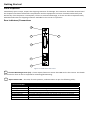
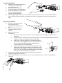
RearIndicators/Connections
Figure1FOM‐90xxRearFace
ChassisMountingScrews(x2)–ThesecaptivefastenerssecuretheFOMcardinthechassis.Theheads
areknurledsothatnotoolisrequiredformounting/dismounting.
OpticsStatusLED–ThisLED,foreachposition,indicatesstatusasperthefollowingtable;
2 3
5
1
4
OpticsStatusLED
Status Description
SteadyGreen Opticsinsyncateachendoflink
FlashingGreen LocalopticalRXisreceivingerrors
SteadyYellow RemoteopticalRXlossofsignalorsync
FlashingYellow LocalopticalRXsignalpresent,butnosync
FlashingOrange Cardtypemismatchatremoteend;thetwocardsarenotcompatible
SteadyRed NoopticalRXsignal
Off Cardfailure
2
1

StatusLED–ThisLED,foreachposition,indicatesstatusasperthefollowingtable;
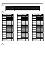
DB‐25MaleConnector(Pins)–Pinoutsareperthefollowingrespectivetables;
OpticalFiberConnections–ThispositionmaybeapairofSTconnectors,SCconnectorsoranSFPslot,if
soordered.
PowerStatusLED
Status Description
SteadyGreen Cardpowersupplynormaloperation
SteadyRed Cardpowersupplyfailureorinover‐currentprotection
Off Cardfailureormainpowerfailure
FOM‐9011 DB‐25Pinout
Channel Lead Pin
8
N.O. 13
Common 25
N.C. 12
7
N.C. 24
Common 11
N.O. 23
6
N.O. 10
Common 22
N.C. 9
5
N.C. 21
Common 8
N.O. 20
4
N.O. 7
Common 19
N.C. 6
3
N.C. 18
Common 5
N.O. 17
2
N.O. 4
Common 16
N.C. 3
1
N.C. 15
Common 2
N.O. 14
ChassisGround
(optionalcable
Shieldconnection)
1
FOM‐9012 DB‐25Pinout
Channel Lead Pin
12 Contact 13
Contact 25
11 Contact 12
Contact 24
10 Contact 11
Contact 23
9 Contact 10
Contact 22
8 Contact 9
Contact 21
7 Contact 8
Contact 20
6 Contact 7
Contact 19
5 Contact 6
Contact 18
4 Contact 5
Contact 17
3 Contact 4
Contact 16
2 Contact 3
Contact 15
1 Contact 2
Contact 14
ChassisGround
(optionalcable
Shieldconnection)
1
FOM‐9010DB‐25Pinout
Channel Lead Pin
12 A 13
B 25
11 A 12
B 24
10 A 11
B 23
9 A 10
B 22
8 A 9
B 21
7 A 8
B 20
6 A 7
B 19
5 A 6
B 18
4 A 5
B 17
3 A 4
B 16
2 A 3
B 15
1 A 2
B 14
ChassisGround
(optionalcable
Shieldconnection)
1
3
4
5

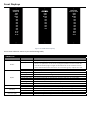
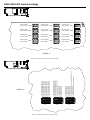
FrontDisplays
Figure2FOM‐90xxDisplay
TheseLEDsindicatesstatusasperthefollowingtable;
Form C Out
Power
Optics
RX Only
Ch 1
Ch 2
Ch 4
Ch 3
Ch 7
Ch 5
Ch 6
Ch 8
FOM-9012
Form A/B Out
Power
Optics
RX Only
Ch 1
Ch 2
Ch 4
Ch 3
Ch 7
Ch 11
Ch 5
Ch 6
Ch 8
Ch 9
Ch 10
Ch 12
FOM-9010
Controls In
Power
Optics
TX Only
Ch 1
Ch 2
Ch 4
Ch 3
Ch 7
Ch 11
Ch 5
Ch 6
Ch 8
Ch 9
Ch 10
Ch 12
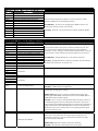
DisplayLEDs
Label Status Description
Power
SteadyGreen Cardpowersupplynormaloperation
SteadyRed Thepowersuppliesonthecardarenotregulatingthecorrectvoltagesor
thereisanopenfuseonthecard.Unplugthepowerfromthecardfor30
secondsandthenplugitinagainsothatthefuseonthecardhastimeto
reset.IfthePowerledisstillredornotaconstantgreen,replacethecard.
Off Cardfailureormainpowerfailure
Optics
SteadyGreen Opticsinsyncateachendoflink
FlashingGreen LocalopticalRXisreceivingerrors
SteadyYellow RemoteopticalRXlossofsignalorsync
FlashingYellow LocalopticalRXsignalpresent,butnosync
FlashingOrange Cardtypemismatchatremoteend;thetwocardsarenotcompatible
SteadyRed NoopticalRXsignal
FlashingRed FOM‐9010setforTXonly,butopticalsignaldetectedatRXoptic
Off Cardfailure
TXOnly SteadyGreen FOMsetforopticalTXonly(FOM‐9010only)
Off Bi‐directionaloperationforstatusreportingfromreceivingend
RXOnly SteadyGreen FOMsetforopticalRXonly(FOM‐9011orFOM‐9012only)
Off Bi‐directionaloperationforstatusreportingtotransmittingend
Channels(All) SteadyYellow CorrespondingControlsignalinOnstate
Off CorrespondingControlsignalinOffstate

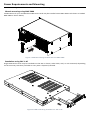
PowerRequirementsandMounting
FlexiblemountingallowstheFOM‐5400tobemountedinanyofanumberofFOM‐serieschassis.
ChassismountingusingRMC‐5000
Combinationsofupto16FiberPlexFOM‐seriescardsmaybeinstalledintoaRMC‐5000rackchassis.Aloaded
RMC‐5000isshownbelow;
Figure3FOMCardbeinginstalledintoanRMC‐5000
StandaloneusingSAC‐1‐AC
SingleFOM‐seriescardsmaybeinstalledintotheSAC‐1chassis,eitherdesk,wall,orrackmounted,depending
ontheaccessorybrackets(includedineverySAC‐1shipment)utilized.
Figure4FOMCardbeinginstalledinaSAC‐1‐AC

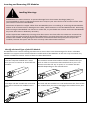
InsertingandRemovingSFPModules
IdentifytheLatchTypeoftheSFPModule
SFPModuleshavevariouslatchingmechanismstosecurethemintotheSFPCageofadevice.FiberPlex
ModulescansupportahostofmanufacturersandbrandsofSFPModulessotheusermayencounterany
numberofdifferentlatches.Someofthesearedescribedbelow.
BailClasp
ThebailclaspSFPmodulehasaclasp
thatyouusetoremoveorinstalltheSFP
module.
ActuatorButton
TheactuatorbuttonSFPmoduleincludesabuttonthatyou
pushinordertoremovetheSFPmodulefromaport.This
buttoncaneitherlift‘Up’orpress‘In’toreleasetheSFP
Moduledependingonthemanufacturer.
MylarTab
TheMylartabSFPmodulehasatabthat
youpulltoremovethemodulefroma
port.
SlideTab
TheslidetabSFPmodulehasatabunderneaththefrontofthe
SFPmodulethatyouusetodisengagethemodulefromaport.
HandlingWarnings
SFPModulesarestaticsensitive.Topreventdamagefromelectrostaticdischarge(ESD),itis
recommendedtoattachanESDpreventativewriststraptoyourwristandtoabaremetalsurfacewhen
youinstallorremoveanSFPModule.
DisconnectallopticalorcoppercablesfromSFPModulespriortoinstallingorremovingtheSFPModule.
Failuretodosocouldresultindamagetothecable,cableconnectorortheSFPModuleitself.Removing
andinsertinganSFPModulecanshortenitsusefullife,soyoushouldnotremoveandinsertSFPModules
anymoreoftenthanisabsolutelynecessary.
ProtectopticalSFPmodulesbyinsertingcleandustcoversintothemafterthecablesareremoved.Be
suretocleantheopticsurfacesofthefibercablesbeforeyouplugthembackintotheopticalportsof
anotherSFPmodule.AvoidgettingdustandothercontaminantsintotheopticalportsofyourSFP
modules,becausetheopticswillnotworkcorrectlywhenobstructedwithdust.

InsertingaModule
1) AttachanESD‐preventativewrist
oranklestrap,followingits
instructionsforuse.
2) Disconnectandremoveall
interfacecablesfromSFPModule.
3) IftheSFPModulehasaBailClasp,
closetheBailClaspbefore
insertingtheSFPModule.
4) Withthegoldfingerconnectoronthebottomandthelabelonthetop,lineuptheSFPModule
withtheemptycageandslideitinmakingsurethatitiscompletelyinsertedandseatedinthe
cage.
RemovingaModule
1) AttachanESD‐preventative
wristoranklestrap,
followingitsinstructionsfor
use.
2) Disconnectandremoveall
interfacecablesfromSFP
Module.
3) Releasethelatching
mechanism.
BailClasp–OpenthebailclaspontheSFPModulewithyourfingerinadownward
direction.
ActuatorButton–Gentlypresstheactuatorup(orin)whilepullingthebodyoftheSFP
ModuletoreleasetheSFPModulefromthecage.
MylarTab–Pullthetabgentlyinastraightoutward
motionuntilitdisengagesfromtheport.Makesurethe
tabisnottwistedwhenpullingasitmaybecome
disconnectedfromtheSFPModule.
SlideTab‐Withyourthumb,pushtheslidetabonthe
bottomfrontoftheSFPmoduleinthedirectionofthe
equipmenttodisengagethemodulefromthelinecard
port.IfyoupullontheSFPmodulewithoutdisengaging
thetab,youcandamagetheSFPmodule.
4) GrasptheSFPModulebetweenyourthumbandindexfingerand
carefullyremoveitfromtheport
5) PlacetheSFPModuleonanantistaticmat,orimmediatelyplaceitinastaticshieldingbagor
container

FOM‐9010DIPSwitchSettings
Figure5DetectionModeDIPSwitches
Figure6PolarityModeDIPSwitches
DETAIL A
SW1 SW2 SW3
SW8
SW5
SW7
SW4
SW9
SW6
SW1SW1
SW1
Detection Mode
Select Channel
Detection Mode
Select Channel
Detection Mode
Select Channel
Detection Mode
Select Channel
Detection Mode
Select Channel
Detection Mode
Select Channel
Detection Mode
Select Channel
Detection Mode
Select Channel
Detection Mode
Select Channel
Detection Mode
Select Channel
Detection Mode
Select Channel
Detection Mode
Select Channel
DETAIL A
S1 S2
1.1 Ch1 Polarity Sense Mode (off) / (on)
1.2 Ch2 Polarity Sense Mode (off) / (on)
1.3 Ch3 Polarity Sense Mode (off) / (on)
1.4 Ch4 Polarity Sense Mode (off) / (on)
1.5 Ch5 Polarity Sense Mode (off) / (on)
1.6 Ch6 Polarity Sense Mode (off) / (on)
1.7 Ch7 Polarity Sense Mode (off) / (on)
1.8 Ch8 Polarity Sense Mode (off) / (on)
2.1 Ch9 Polarity Sense Mode (off) / (on)
2.2 Ch10 Polarity Sense Mode (off) / (on)
2.3 Ch11 Polarity Sense Mode (off) / (on)
2.4 Ch12 Polarity Sense Mode (off) / (on)
2.5 Unused (Should be off)
2.6 Unused (Should be off)
2.7 Unused (Should be off)
2.8 Unused (Should be off)
3.2 Unused (Should be off)
3.1 Unused (Should be off)
3.3 Unused (Should be off)
3.7 Unused (Should be off)
3.6 Full Duplex (bi-directional) / (uni-directional) Optical Tx Only
3.5 Unused (Should be off)
3.4 Unused (Should be off)
3.8 Display Test (normal operation) / (test flashing)
S3

FOM‐9010Figure5DetectionModeDIPSwitches
Switch Parameter
SW1 DetectionModeSelectChannel1
TheseselectVoltageSenseModeorContactClosure/Open
CollectorModeforcorrespondingchannel.
DOWN(OFF)‐ChannelisinVoltageSenseMode.SeeS1/S2
settingsforfurthercontrolinthismode.
UP(ON)‐ChannelisinContactClosure/OpenCollectorMode.
SW2 DetectionModeSelectChannel2
SW3 DetectionModeSelectChannel3
SW4 DetectionModeSelectChannel4
SW5 DetectionModeSelectChannel5
SW6 DetectionModeSelectChannel6
SW7 DetectionModeSelectChannel7
SW8 DetectionModeSelectChannel8
SW9 DetectionModeSelectChannel9
SW10 DetectionModeSelectChannel10
SW11 DetectionModeSelectChannel11
SW12 DetectionModeSelectChannel12
FOM‐9010Figure6PolarityModeDIPSwitches
Switch Parameter
S1.1 PolaritySenseMode,Channel1
Theseselectwhethertheinputispolaritysensitiveornot.This
onlyappliesiftheDetectionModeswitchfortherespective
channelissetfor‘Voltage’.IftheDetectionModeswitchissetfor
‘dryContacts/OpenCollector’thenthisswitchhasnofunction.
DOWN(OFF)‐Voltagedetectionisnotpolaritysensitive.
UP(ON)‐Voltagedetectionispolaritysensitive.‘B’leadmustbe
positivewithrespectto‘A’leadfor‘on’.
S1.2 PolaritySenseMode,Channel2
S1.3 PolaritySenseMode,Channel3
S1.4 PolaritySenseMode,Channel4
S1.5 PolaritySenseMode,Channel5
S1.6 PolaritySenseMode,Channel6
S1.7 PolaritySenseMode,Channel7
S1.8 PolaritySenseMode,Channel8
S2.1 PolaritySenseMode,Channel9
S2.2 PolaritySenseMode,Channel10
S2.3 PolaritySenseMode,Channel11
S2.4 PolaritySenseMode,Channel12
S2.5
Reserved
S2.6
S2.7
S2.8
S3.1
Reserved
S3.2
S3.3
S3.4
S3.5 RemoteConfiguration DOWN(OFF)‐Allowremoteconfiguration
UP(ON)–Inhibitremoteconfiguration
S3.6 OpticalTXOnly EnablesordisablesthelocalRXopticsoperation.Powermustbe
cycledafterchangingthissetting.
DOWN(OFF)‐RXopticsareactiveinbidirectionalopticallink
allowingtheFOM‐9010todisplaythestatusoftheFOM‐9011or
FOM‐9012localRXopticalsignal.
UP(ON)‐UnitisTXonly.TheOPTICSledwillnotlight,asthereis
noexpectedsignalatthelocalRXopticalconnector.Ifthereisa
signalpresenttheOPTICSledwillflashred,indicatingthatthereis
asignalattachedtotheFOM‐9010whenonewasnotexpected.
Whenthelinkisinthismode,thereisnoreportingofthesignal
statusfromthefarend.
S3.7 Reserved
S3.8
LEDoperationMode
NormalLEDoperationsettingwillcausethefrontpaneldisplayto
flasheachoftheindicatorsanalternatingredandgreenfor
verificationpurposes.Theunitcontinuestofunctionnormally‐
onlythedisplayisaffected.
DOWN(OFF)‐Normalindicatoroperationselected.
UP(ON)‐Allindicatorsalternatelyflashredorgreen.

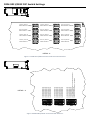
FOM‐9011/9012DIPSwitchSettings
Figure7FOM‐9011/9012ContactSelectionDIPSwitches
Figure8FOM‐9011/9012FunctionalDIPSwitches
DETAIL A
SW1 SW2 SW3
SW8
SW5
SW7
SW4
SW9
SW6
SW12SW11SW10
Form A / Form B
Select Channel 1
Form A / Form B
Select Channel 2
Form A / Form B
Select Channel 4
Form A / Form B
Select Channel 9
Form A / Form B
Select Channel 8
Form A / Form B
Select Channel 5
Form A / Form B
Select Channel 6
Form A / Form B
Select Channel 3
Form A / Form B
Select Channel 11
Form A / Form B
Select Channel 10
Form A / Form B
Select Channel 7
Form A / Form B
Select Channel 12
DETAIL A
S1 S2
1.1 Unused (Should be off)
1.2 Unused (Should be off)
1.3 Unused (Should be off)
1.4 Unused (Should be off)
1.5 Unused (Should be off)
1.6 Unused (Should be off)
1.7 Unused (Should be off)
1.8 Unused (Should be off)
2.1 Unused (Should be off)
2.2 Unused (Should be off)
2.3 Unused (Should be off)
2.4 Unused (Should be off)
2.5 Unused (Should be off)
2.6 Unused (Should be off)
2.7 Unused (Should be off)
2.8 Unused (Should be off)
3.2 Unused (Should be off)
3.1 Unused (Should be off)
3.3 Unused (Should be off)
3.7 Unused (Should be off)
3.6 Full Duplex (bi-directional) / (uni-directional) Optical Rx Only
3.5 Unused (Should be off)
3.4 Unused (Should be off)
3.8 Display Test (normal operation) / (test flashing)
S3

FOM‐9011/9012Figure7FOM‐9011/9012 ContactSelectionDIPSwitches
Switch Parameter
SW1 FormA/FormBSelectChannel1
SelectsFormAorFormBcontactsoutforcorrespondingchannel.
DOWN(OFF)‐FormA(NormallyOpen)contactsout.
UP(ON)‐FormB(NormallyClosed)contactsout.
SW2 FormA/FormBSelectChannel2
SW3 FormA/FormBSelectChannel3
SW4 FormA/FormBSelectChannel4
SW5 FormA/FormBSelectChannel5
SW6 FormA/FormBSelectChannel6
SW7 FormA/FormBSelectChannel7
SW8 FormA/FormBSelectChannel8
SW9 FormA/FormBSelectChannel9
SW10 FormA/FormBSelectChannel10
SW11 FormA/FormBSelectChannel11
SW12 FormA/FormBSelectChannel12
FOM‐9011/9012Figure8FOM‐9011/9012 FunctionalDIPSwitches
Switch Parameter
S1.1
Reserved
S1.2
S1.3
S1.4
S1.5
S1.6
S1.7
S1.8
S2.1
Reserved
S2.2
S2.3
S2.4
S2.5
S2.6
S2.7
S2.8
S3.1
Reserved
S3.2
S3.3
S3.4
S3.5 RemoteConfiguration DOWN(OFF)‐Allowremoteconfiguration
UP(ON)–Inhibitremoteconfiguration
S3.6 OpticalTXOnly OpticalRXonlycontrolsthelocalTXopticsforbidirectionalorone‐
wayoperation.
DOWN(OFF)‐TXopticsareactiveinbidirectionalopticallink.
UP(ON)‐UnitisRXonly.NoTXdataissentoutofoptics.Thelocal
OPTICSledwillonlyindicatethestatusofthelocalopticalRX.
Whenthelinkisinthismode,thereisnoreportingoftheoptical
signalstatusbacktothetransmittingend.
S3.7 Reserved
S3.8
LEDoperationMode
NormalLEDoperationsettingwillcausethefrontpaneldisplayto
flasheachoftheindicatorsanalternatingredandgreenfor
verificationpurposes.Theunitcontinuestofunctionnormally‐
onlythedisplayisaffected.
DOWN(OFF)‐Normalindicatoroperationselected.
UP(ON)‐Allindicatorsalternatelyflashredorgreen.

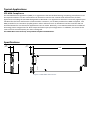
.80
[20.4] 11. 5 0 X
.50
[12.7]
5.22X
TypicalApplications
SFPMSACompliance
TheSFPMultisourceAgreement(MSA)isanagreementthatwasdraftedamongcompetingmanufacturersof
SFPopticalmodules.TheSFFCommitteewasformedtooverseethecreationandmaintenanceofthese
agreementsincludingtheSFPMSAdesignatedasINF‐8074i.Thisagreementdescribesamutuallyagreedupon
standardfortheformandfunctionofSFPmodules.However,notallSFPsproducedareMSAcompliant.The
MSAprovidesforatransceiver(TX/RX)pinout.OtherindustriessuchasbroadcasthadtheneedfordualTX
anddualRXSFPforuni‐directionalapplicationssuchasvideo.Naturally,anon‐MSAstandardwasintroduced
allocatingpinoutassignmentsfordualoutputanddualinputI/Oconfigurations.Inaddition,thesomeofthe
internalserialcommunicationpinswerereassigned.
TheFOM‐90xxserieswillonlyacceptMSAcompliantSFPModules.
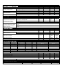
Specifications
Figure5FOM‐90xxDimensions

ELECTRICALSPECIFICATIONS
Min Typ Max Unit
PowerRequirement VoltageRange 20 24 34 V
FOM‐90xxSupplyCurrent ‐ 250 ‐ mA
Min Typ Max Unit
Environmental StorageTemperature ‐40 ‐ 85 °C
OperatingTemperature 0 ‐ 50 °C
InterfaceConnector FOM‐90xx DB‐25(MIL‐C‐24308Type)
FOM‐9010
Min Typ Max Unit
VoltageSenseorPolarity
SensitiveStatedetection
mode(Channelsare
isolatedinthismode)
SwitchingRate(approx.)‐fasterratesare
sensedasasteady'ON' 0 ‐ 63 ms
SamplingJitter 0 ‐ 10 %
InputVoltageRange 3 ‐ 65 VDC
ContactSenseorOpen
Collectordetectionmode
(Channelshavecommon
SignalGround)
ALead:Sources10‐12VDC@4.5maforrelaycontactconnectionoropencollectordriver
input
BLead:SignalGroundforrelaycontactconnectionorgroundreferenceforopencollector
driver
FOM‐9011/‐9012
Min Typ Max Unit
OnResistance ‐ ‐ 15 Ω
OffResistance FormAContacts 350 ‐ ‐ MΩ
FormBContacts ‐ ‐ 100
MaximumVoltage 0 ‐ 200
VDCor
Peak
VAC
MaximumCurrent 0 ‐ 200 mA
FormCBreak‐Before‐MakeTime 3 ‐ 5 ms
OPTICALSPECIFICATIONS
OrderSuffix Fiber FiberType Connector λ
(nm)
TransmitterPower
(dBm)
ReceiverSensitivity
(dBm)
T12 Multimode OM2 ST 850 ‐5 ‐20
T22 Multimode OM2 ST 1310 ‐12 ‐26
L12 Multimode OM2 LC 850 ‐9.5 ‐17
L22 Multimode OM2 LC 1310 ‐15 ‐24
T5B Singlemode OS1,OS2 ST 1310 ‐11 ‐23
L5B Singlemode OS1,OS2 LC 1310 ‐9.5 ‐19
C SFPCagewithnoOpticalModuleInstalled
ExternalSFPInterface Min Typ Max Unit
DataRate ‐ 245 ‐ Mbps
RecommendedJitter ‐ 40 ‐ psec
OperatingVoltage ‐ 3.3 VDC
MaximumCurrent ‐ ‐ 500 mA
OpticalModules SFPMSA(SFF‐8431,SFF‐8432,SFF‐8433)compliantslot,datarate1.25Gbps
PHYSICALSPECIFICATIONS
CaseDimensions Length Width Height Weight
FOM‐90xx 12.0in(305mm) 0.80in(20mm) 5.22in(133mm) 0.4lb(0.18kg)

18040-412 Guilford Rd. • Annapolis Junction, MD 20701
fiberplex.com • [email protected]
• 301.604.0100
UMFM901x
170821
-
 1
1
-
 2
2
-
 3
3
-
 4
4
-
 5
5
-
 6
6
-
 7
7
-
 8
8
-
 9
9
-
 10
10
-
 11
11
-
 12
12
-
 13
13
-
 14
14
-
 15
15
-
 16
16


Fiberplex FOM-9010 User manual
- Type
- User manual
Ask a question and I''ll find the answer in the document
Finding information in a document is now easier with AI
Related papers


Other documents
-
Applied Motion Products STRAC2 User guide
-
CTC Union iSAP5100 User manual
-
Siemens SWT-3000 Equipment Manual
-
-
Mircom LT-894 FleXNet Operating instructions
-
Cobalt Digital 9404-EO 4K/3G/HD/SD-SDI/ASI/MADI Quad-Channel Fiber Optic Transmitters User manual
-
 Versitron F22xxA Technical Manual
-
 Versitron F28xxD Technical Manual
-
-
 Versitron F28xxD Owner's manual


