Page is loading ...

1
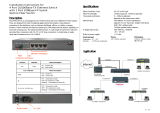
iSAP5100
Integrated Service Access Platform

2
LEGAL
The information in this publication has been carefully checked and is believed to be entirely accurate at the time of
publication. CTC Union Technologies assumes no responsibility, however, for possible errors or omissions, or for any
consequences resulting from the use of the information contained herein. CTC Union Technologies reserves the right to
make changes in its products or product specifications with the intent to improve function or design at any time and
without notice and is not required to update this documentation to reflect such changes.
CTC Union Technologies makes no warranty, representation, or guarantee regarding the suitability of its products for
any particular purpose, nor does CTC Union assume any liability arising out of the application or use of any product
and specifically disclaims any and all liability, including without limitation any consequential or incidental damages.
CTC Union products are not designed, intended, or authorized for use in systems or applications intended to support or
sustain life, or for any other application in which the failure of the product could create a situation where personal injury
or death may occur. Should the Buyer purchase or use a CTC Union product for any such unintended or unauthorized
application, the Buyer shall indemnify and hold CTC Union Technologies and its officers, employees, subsidiaries,
affiliates, and distributors harmless against all claims, costs, damages, expenses, and reasonable attorney fees arising
out of, either directly or indirectly, any claim of personal injury or death that may be associated with such unintended or
unauthorized use, even if such claim alleges that CTC Union Technologies was negligent regarding the design or
manufacture of said product.
WARNING:
This equipment has been tested and found to comply with the limits for a Class A digital device, pursuant to Part 15 of
the FCC Rules. These limits are designed to provide reasonable protection against harmful interference when the
equipment is operated in a commercial environment. This equipment generates, uses, and can radiate radio frequency
energy and if not installed and used in accordance with the instruction manual may cause harmful interference in which
case the user will be required to correct the interference at his own expense. NOTICE: (1) The changes or modifications
not expressively approved by the party responsible for compliance could void the user's authority to operate the
equipment. (2) Shielded interface cables and AC power cord, if any, must be used in order to comply with the emission
limits.
CISPR PUB.22 Class A COMPLIANCE:
This device complies with EMC directive of the European Community and meets or exceeds the following technical
standard. EN 55022 - Limits and Methods of Measurement of Radio Interference Characteristics of Information
Technology Equipment. This device complies with CISPR Class A.
WARNING:
This is a Class A product. In a domestic environment this product may cause radio interference in which case the user
may be required to take adequate measures.
CE NOTICE
Marking by the symbol CE indicates compliance of this equipment to the EMC directive of the European Community.
Such marking is indicative that this equipment meets or exceeds the following technical standards: EN
55022:1994/A1:1995/A2:1997 Class A and EN61000-3-2:1995, EN61000-3-3:1995 and EN50082-1:1997

3
CTC Union Technologies Co., Ltd.
Far Eastern Vienna Technology Center (Neihu Technology Park)
8F, No. 60, Zhouzi St.
Neihu, Taipei, 114
Taiwan
Phone: +886-2-2659-1021
FAX: +886-2-2799-1355
iSAP5100
Integrated Service Access Platform
User Manual
Version 0.9e July 2015 (draft)
This manual supports the following models:
iSAP5100
This document is the current official release manual. Please check CTC Union's website for any updated manual or
contact us by E-mail at sales@ctcu.com. Please address any comments for improving this manual or to point out
omissions or errors to marketing@ctcu.com. Thank you.
2012-13 CTC Union Technologies Co.,Ltd.
All Rights Reserved
The contents of this document are subject to change without any prior notice.

Table of Contents
4
CHAPTER 1. INTRODUCTION ................................................................................................................................... 6
1.1 PRODUCT DESCRIPTION ............................................................................................................................................. 6
1.2 SUPPORTED MODULES ............................................................................................................................................... 6
1.2.1 Overall Functions ........................................................................................................................................ 7
1.2.2 5100-MS-DM-96 Card ................................................................................................................................ 7
1.2.3 5100-MS-DM-155 Card .............................................................................................................................. 8
1.2.4 iSAP-FOM Card .......................................................................................................................................... 8
1.2.5 iSAP-E1 Card .............................................................................................................................................. 8
1.2.6 iSAP-FXO Card .......................................................................................................................................... 9
1.2.7 iSAP-FXS Card ........................................................................................................................................... 9
1.2.8 iSAP- E&M Card ........................................................................................................................................ 9
1.2.9 iSAP-G703/64K Card .................................................................................................................................. 9
1.2.10 iSAP-RS232 Card ........................................................................................................................................ 9
1.2.11 iSAP-RS232-C Card .................................................................................................................................... 9
1.2.12 iSAP-ET100 Card ........................................................................................................................................ 9
1.2.13 iSAP-N x 64K Card ..................................................................................................................................... 9
1.3 SPECIFICATIONS ...................................................................................................................................................... 10
1.3.1 Chassis Hardware Spec. ........................................................................................................................... 10
1.3.2 5100-MS-DM-96 Card .............................................................................................................................. 10
1.3.3 5100-MS-DM-155 Card ............................................................................................................................ 10
1.3.4 iSAP-FOM01 Card .................................................................................................................................... 10
1.3.5 iSAP-FOM02 Card .................................................................................................................................... 11
1.3.6 iSAP-8E1 Card .......................................................................................................................................... 11
1.3.7 iSAP-16E1 Card ........................................................................................................................................ 11
1.3.8 iSAP-FXO Card ........................................................................................................................................ 12
1.3.9 iSAP-FXS Card ......................................................................................................................................... 12
1.3.10 iSAP-E&M Card ....................................................................................................................................... 12
1.3.11 iSAP-G703/64K Card ................................................................................................................................ 13
1.3.12 iSAP-RS232 Card ...................................................................................................................................... 13
1.3.13 iSAP-RS232-C Card .................................................................................................................................. 13
1.3.14 iSAP-ET100 Ethernet Bridge Line Card .................................................................................................. 13
1.3.15 iSAP-N x 64K Card ................................................................................................................................... 13
CHAPTER 2. PANEL DESCRIPTIONS ..................................................................................................................... 14
2.1 5100- MS-DM CARD .............................................................................................................................................. 14
2.1.1 5100-MS-DM-96 Card .............................................................................................................................. 14
2.1.2 5100-MS-DM-155 Card ............................................................................................................................ 14
2.2 ISAP-FOM CARD ................................................................................................................................................... 15
2.2.1 iSAP-FOM01 Card .................................................................................................................................... 15
2.2.2 iSAP-FOM02 Card .................................................................................................................................... 16
2.3 ISAP-E1 CARD ........................................................................................................................................................ 17
2.3.1 iSAP-8E1 Card .......................................................................................................................................... 17
2.3.2 iSAP-16E1 Card ........................................................................................................................................ 17
2.4 IO CARD .................................................................................................................................................................. 17
2.4.1 iSAP-RS232 Card ...................................................................................................................................... 17
2.4.2 iSAP-RS232-C Card .................................................................................................................................. 18
2.4.3 iSAP-G703/64K Card ................................................................................................................................ 18
2.4.4 iSAP-E&M Card ....................................................................................................................................... 19
2.4.5 iSAP-FXO Card ........................................................................................................................................ 19
2.4.6 iSAP-FXS Card ......................................................................................................................................... 20
2.4.7 iSAP-ET100 Card ...................................................................................................................................... 20
2.4.8 iSAP-N×64K Card .................................................................................................................................... 21
2.4.9 iSAP-AC/DC Power Card ......................................................................................................................... 21
CHAPTER 3. INSTALLATION ................................................................................................................................... 23
3.1 RACK MOUNTING .................................................................................................................................................... 23
3.2 INSTALL THE MANAGEMENT CARD ......................................................................................................................... 23
3.2.1 Connect SNMP Management to Network .................................................................................................. 23
3.2.2 Console Terminal Connection ................................................................................................................... 24

Table of Contents
5
3.2.3 STM1 Interface .......................................................................................................................................... 24
3.3 E1 CARD ................................................................................................................................................................. 24
3.4 IO CARD .................................................................................................................................................................. 25
3.4.1 FXO Card Pinouts ..................................................................................................................................... 25
3.4.2 FXS Card Pinouts ..................................................................................................................................... 25
3.4.3 E&M Card Hardware Setup (DIP SWITCH) ............................................................................................ 25
3.4.4 RS232/RS232-C Card Pinouts................................................................................................................... 26
3.4.5 G703/64K Card Pinouts ............................................................................................................................ 28
3.4.6 N×64K Card Pinouts ................................................................................................................................ 28
3.5 ALARM RELAY CONNECTIONS ................................................................................................................................ 30
CHAPTER 4. PROVISIONING ................................................................................................................................... 32
4.1 OVERVIEW OF THE PROCEDURE .............................................................................................................................. 32
4.1.1 Login ......................................................................................................................................................... 32
4.1.2 Configure the Clock Source ...................................................................................................................... 33
4.1.3 E1 Framing Configuration ........................................................................................................................ 33
4.1.4 Set up the Digital Cross Connection ......................................................................................................... 34
4.2 MULTIPLEXING CONFIGURATIONS .......................................................................................................................... 34
4.2.1 E1 Cross Connect to SDH ......................................................................................................................... 34
4.2.2 IO Card Cross Connect to E1 ................................................................................................................... 34
4.2.3 IO Card Cross Connect to E1 in SDH ...................................................................................................... 34
4.3 MIRRORING AN E1 CHANNEL .................................................................................................................................. 35
4.4 BROADCAST E1 ....................................................................................................................................................... 35
4.4.1 Configure Broadcast Source ..................................................................................................................... 35
4.4.2 Configure Broadcast Listener ................................................................................................................... 35
4.5 CONFIGURING REDUNDANCY .................................................................................................................................. 36
4.5.1 Optical Port Redundancy Setup ................................................................................................................ 36
4.5.2 E1 Redundancy Setup ................................................................................................................................ 36
4.6 SNMP MANAGEMENT ............................................................................................................................................. 36
4.6.1 SNMP Setup .............................................................................................................................................. 36
4.6.2 IP Address Setup ....................................................................................................................................... 36
4.6.3 SNMP Server IP Address Setup................................................................................................................. 36
4.6.4 SNMP TRAP Address Setup ...................................................................................................................... 36
4.6.5 Network Level Setup .................................................................................................................................. 36
4.6.6 Configure Time Slot .................................................................................................................................. 37
4.7 CONFIGURE SYSTEM PARAMETERS ......................................................................................................................... 37
4.7.1 Save ........................................................................................................................................................... 37
4.7.2 Set Time ..................................................................................................................................................... 37
4.7.3 Line............................................................................................................................................................ 37
4.8 DIAGNOSTICS CONFIGURATION ............................................................................................................................... 37
4.8.1 E1 Card Loopback Setup ........................................................................................................................... 37
4.8.2 E1 card BERT setup .................................................................................................................................. 38

CHAPTER 1. INTRODUCTION
6
Chapter 1. Introduction
1.1 Product Description
iSAP5100 is an integrated service access platform, housed in a 19 inch rack mountable chassis that
offers 18 card slots, 2 card slots for management, and 2 modular power card slots.
iSAP5100 employs Time Division-Multiplexing with support for up to 96 E1 channels (6x16E1) that
provide functions of multiplexing and cross-connection of data/voice/CAS-signaling. The MUX is designed
for multiplexing Nx64Kbps, 64K/128Kbps, 9.6Kbps synchronous data, asynchronous data below 19.2Kbps ,
G703/64K data and FXO, FXS, E&M voice signals into 2.048Mbps ITU-T G.703 E1 frames. The cross-
connecting function includes the intercrossing of CAS-signaling.
The types and quantity of subscriber's data and voice interface modules can be flexibly selected
according to needs. The modules can be plugged into any of the 18 available card slots according to specific
maintenance and application methods. All time slots may be user defined.
iSAP5100 supports SNMP network management. When SNMP management mode is available and
selected, the Web based GUI provides an intuitive and easy to use graphical interface to provision and
monitor all operations of the iSAP5100. A console terminal mode is supported as well for local
configuration via a Command Line Interface.
1.2 Supported modules
NMS Card: 5100- MS-DM-96 (E1), 5100 - MS-DM-155 (STM-1)
FOM Modules: iSAP-FOM01, iSAP-FOM02
E1 Modules: 5100-8E1 (8-CH), 5100-16E1 (16-CH)
AC Power Module: 5100-AC240 (100~240VAC)
DC Power Module: 5100-DC240 (-48VDC)
I/O Modules:
5100-RS232 (6-CH RS-232 SYNC),
5100-RS232-C (6-CH RS-232 ASYNC),
5100-N *64K (4-CH Nx64K SYNC V.35),
5100-G703/64K (6-CH 64K G.703 co-directional),
5100-ET100 (2-CH Ethernet Bridge),
5100-E&M (8-CH E&M Voice),
5100-FXS (8-CH FXS),
5100-FXO (8-CH FXO),
Figure 1: Front View

CHAPTER 1. INTRODUCTION
7
1.2.1 Overall Functions
iSAP5100 provides resilient operation through redundancy. The front of the chassis can house up of
two management cards, two power modules and two fan modules. When two power modules are inserted,
power redundancy is provided in case of a single power module failure. The power modules can be selected
from either AC or DC power types. By mixing and matching the designer can select AC+AC, AC+DC or
DC+DC redundant combinations.
The management card provides the configuration management for all other cards, including E1 cards
and various IO cards. A pair of management cards provides 1+1 protection, keeping one card always in a
working state and minimizing any loss due to management downtime.
Figure 2: Rear View
The rear of the chassis offers 18 slots in total. E1 cards can be inserted in Slot 1~6 which support 16-
channel E1. Slot 7-18 are extension slots for E1 which support 4-channel 8E1/16E cards. IO cards
(including FXO card, FXS card, E&M card, G703-64K card, RS232 card, R232-C card, N *64K card,
ET100 card, RS485 card) can be placed in Slot 1-18.
Figure 3: Rear Panel of the Chassis
1.2.2 5100-MS-DM-96 Card
This management card inserted in the front of chassis provides the 10/100M out-band Ethernet network
management interface.
Users can manage IO cards via RS232 console port.
The chassis also supports voice, data, non-blocking switching functions as follows:
Maximum 144 E1 (E1 slot, IO slot access E1 quantity) non-blocking switching.
Support E1 multiplexing, timeslot, broadcast functions.

CHAPTER 1. INTRODUCTION
8
Support synchronous exchange between CAS signaling of 16 timeslots and voice timeslots.
Support 144 x E1 the recovered clock optional synchronization function.
The management card supports card failover backup function:
The management card supports card failover with switching time of <50mS.
All clock synchronization follows the main working management card.
If fault occurs in the main working card, the backup card will automatically switch to restore the main
operation.
1.2.3 5100-MS-DM-155 Card
MS-DM-155 card supports one 155M SDH for 63 x E1 interfaces. The 155M interface provides
management that prepares against and aids and switches over the function independently.
The front panel offers a 10/100M out-band Ethernet network management interface.
Configuration can be done via RS232 serial console and CLI for native E1 and low-speed IO cards.
Supports voice, data, non-blocking switching function as follows:
Maximum 144 E1 (E1 slot, IO slot access E1 quantity) non-blocking switching.
155M optical port provides a total of 63xE1 non-blocking switching.
Support E1 multiplexing, timeslot, and broadcast the function.
Support synchronous exchange between CAS signaling of 16 timeslots and voice timeslots.
Support bi-directional add-drop connection between 63E1*32TS of 155M optical port and 144E1*32TS
of E1/IO slot.
Support alarm and error statistics:
STM-1 Alarm indication: LOS, LOF, RDI, HP-AIS, HP-LOP, LP-AIS, LP-LOP; BER: B1, B2, B3
E1 Alarm indication: LOS, LOF, AIS, RAI; BER: FRR, CRC
Support BERT line loopback test function.
Support the flexible clock synchronization function:
Support any one of 144 E1 lines as recovery clock source.
The management card supports card failover backup function:
The management card supports card failover with switching time of <50mS.
All clock synchronization follows the main working management card.
If fault occurs in the main 155M working card, the backup 155M card will automatically switch to
restore the main operation.
1.2.4 iSAP-FOM Card
iSAP-FOM card contains iSAP-FOM01 and iSAP-FOM02 types. Both types can support uplink single fiber
and dual fiber. The fiber adheres to PDH155M standard 1x9 fiber with FC connector. The distance can
reach up to 20km (changeable upon request). iSAP-FOM provides two shared 100M Ethernet connectors
and supports isolation, switching mode, 4E1 ports, VLAN. The iSAP-FOM card also supports frame,
unframe, E1 module interconnection, 1+1 redundancy for uplink fiber ports and flexible setup for 4E1 and
I/O module.
1.2.5 iSAP-E1 Card
Support 8 E1 and 16 E1 (RJ-45 interface).
Support CRC checksum.
Support 120 ohm and 75 ohm.
Sensitivity: -20dB, -43dB (selectable).
System clock modes: Any one of the channels in 8/16 E1 can be selected as system synchronization
clock.
Support E1 module backup.
Support local, remote and bidirectional loopback test.
Support BERT test function.
Support E1 alarm and checksum monitoring and statistics:
Alarm: LOS, LOF, AIS, RAI
Checksum: ERR, CRC

CHAPTER 1. INTRODUCTION
9
1.2.6 iSAP-FXO Card
Each card provides 8-channel FXO.
1.2.7 iSAP-FXS Card
Each card provides 8-channel FXS and can be interflowed with the other side FXO interface under the
ordinary way. Hot Line mode can support point-to-point connection.
1.2.8 iSAP- E&M Card
Each card provides 8-channel E&M ports. Each channel supports 2 or 4 wires for voice transmission and
E&M signaling with TYPE1 to TYPE5 for selection.
Supports data, voice, and civil aviation working modes.
Input and output gains are adjustable.
Supports local and remote loopback test.
1.2.9 iSAP-G703/64K Card
Each card supports 4-channel G703/64Kbps Co-directional, Contra-directional and Centra-directional
connectors.
Each channel’s speed is 64Kbps and supports local and remote loopback test.
1.2.10 iSAP-RS232 Card
Each card supports 6-port RS232 connector.
Each port supports speed of ≦38.4kbps (asynchronous).
Each port supports speed of 2.4/4.8/9.6/19.2/38.4/64kbps (synchronous).
DCE interface.
Supports local and remote loopback test.
1.2.11 iSAP-RS232-C Card
Each card supports 6-port RS232 connector.
Each port supports speed of ≦38.4kbps (asynchronous).
Each port supports speed of 2.4/4.8/9.6/19.2/38.4/64kbps (synchronous).
DCE interface.
Supports local and remote loopback test.
1.2.12 iSAP-ET100 Card
Each card supports 4 x 10/100Base-T Auto MDI/MDIX channels.
Supports speed of n x 64kbps.
Supports Flow Control function.
Ethernet Bridge Tributary card provides Ethernet over E1 capability.
Supports local and remote loopback test.
1.2.13 iSAP-N x 64K Card
Each card supports 4 N x 64kbps (N= 1~31) high-speed channels.
Supports DCE interface.

CHAPTER 1. INTRODUCTION
10
1.3 Specifications
1.3.1 Chassis Hardware Spec.
Dimensions:
440 mm (W) x 350 mm (D) x 187 mm (H)
Temperature:
0~60℃ (working temperature), -25~70℃ (storage temperature)
Humidity
10%~90% (non-condensing)
Power
AC 220V: 165~265V, 50~60Hz
AC 110/220V: 90~265V, 50~ 60Hz
DC -48V: -36~ -72VDC
Consumption
<240W (fully loaded chassis)
1.3.2 5100-MS-DM-96 Card
NMS interface: Ethernet 10/100Base-TX, RJ45 (Auto-Negotiation)
Console port: Serial RS232 interface, DB9 (Female)
Cross connect capacity: 144 E1s non-blocking connections. Support E1 mirror and broadcast function.
CAS signaling exchange: Cross connect between CAS signals of 16 timeslots and voice timeslots.
1.3.3 5100-MS-DM-155 Card
Data port: Offer one 155M SFP interface. Two SFP fiber ports react as backup for each other.
NMS interface: Ethernet 10/100Base-TX, RJ45 (Auto-Negotiation)
Console port: Serial RS232 interface, DB9 (Female)
Cross connect capacity: 144 E1 has no non-blocking exchange. 155M fiber 63E1 and 144 E1 have no
non-blocking exchange. Support the replication of E1, time slot, broadcast function.
CAS signaling exchange: Cross connect between CAS signals of 16 timeslots and voice timeslots.
STM-1/E1 multiplexing and de-multiplexing: Support bi-directional cross connection between 63E1
*32TS of STM-1 and 144E1 *32TS of E1/IO slot.
1.3.4 iSAP-FOM01 Card
Uplink Fiber
The number of port: 1
Data rate: 155M
Connector: FC
Ethernet
The number of port: 2
Connector: RJ-45
Speed: 10/100Mbps Full Duplex, Auto-Negotiation
E1 Port
The number of port: 4 channels
Connector: RJ45 or BNC (via RJ45 to BNC cable)
Line code: HDB3
Line impedance: 75 ohms (Unbalanced) or 120 ohms (Balanced)
"Pulse" amplitude: Nominal 2.37V (75 ohms) or Nominal 3.00V (120 ohms)
ITU standards: G.703, G.704, G.732, G.823

CHAPTER 1. INTRODUCTION
11
1.3.5 iSAP-FOM02 Card
Uplink Fiber
The number of port: 2
Data rate: 155M
Connector: FC
Ethernet
The number of port: 2
Connector: RJ-45
Speed: 10/100Mbps Full Duplex, Auto-Negotiation
E1 Port
The number of port: 4 channels
Connector: RJ45 or BNC (via RJ45 to BNC cable)
Line code: HDB3
Line impedance: 75 ohms (Unbalanced) or 120 ohms (Balanced)
"Pulse" amplitude: Nominal 2.37V (75 ohms) or Nominal 3.00V (120 ohms)
ITU standards: G.703, G.704, G.732, G.823
1.3.6 iSAP-8E1 Card
Frame Format: CAS (PCM30)/CCS (PCM31)/Unframe
CRC: ON/OFF
Loopback: Local loopback (LLB), remote loopback (RLB), bi-directional loopback
Speed: 2.048Mbps
Interface: RJ45 or BNC (transfer to BNC via RJ45)
Line Coding: HDB3/AMI
Rx Sensitivity: -20/-43dB
Line Impedance: 75 ohm (unbalanced)/120 ohm (balanced)
Level Range: 2.37V (75 ohm)/ 3.00V (120 ohm)
Jitter Performance: Comply with ITU G.823 (equipped with jitter attenuator)
ITU Standards: G.703, G.704, G.732, G.823
Internal BERT test
1.3.7 iSAP-16E1 Card
Frame Format: CAS (PCM30)/CCS (PCM31)/Unframe
CRC: ON/OFF
Loopback: Local loopback (LLB), remote loopback (RLB), bi-directional loopback
Speed: 2.048Mbps
Interface: RJ45 or BNC (transfer to BNC via RJ45)
Line Coding: HDB3/AMI
Rx Sensitivity: -20/-43dB
Line Impedance: 75 ohm (unbalanced)/120 ohm (balanced)
Level Range: 2.37V (75 ohm)/ 3.00V (120 ohm)
Jitter Performance: Comply with ITU G.823 (equipped with jitter attenuator)
ITU Standards: G.703, G.704, G.732, G.823
Internal BERT test

CHAPTER 1. INTRODUCTION
12
1.3.8 iSAP-FXO Card
Surge Protection: 1500V
Voltage Protection: 220V
Ringing Voltage Range: 35V-90V
Ringing Frequency Range: 17Hz- 60Hz
The direct current resistance in the off-hook condition is not more than 300 ohm
Line Resistance: 600 ohm
Channel Frequency: +/-0.5dB
Idle Channel: >70dB
AD (TX) Gain: 0dB
DA (RX) Gain:-3.5dB
When ringing signals are active, the indicator will be lit.
ITU-T Standards: G.712, G.713, G.714
1.3.9 iSAP-FXS Card
Surge Protection: 1500V
Voltage Protection:220V
Ringing Output: 75V, Frequency 25Hz
Battery Source: -48V, 22mA (current)
Line Resistance: 600 ohm
Channel Frequency: +/-0.5dB
Idle Channel: >70dB
AD (TX) Gain: 0dB
DA (RX) Gain:-3.5dB
ITU-T Standards: G.712, G.713, G.714
1.3.10 iSAP-E&M Card
Signaling:
E circuit & M circuit are used as the inter-office signaling of the control circuit interface
transmission.
Provides E circuit, M circuit, SB (Battery) and SG (Earth) lines.
Range of Loop Current: 5~30 mA, maximum 70 mA
Each E & M channel can provide 5 signaling modes (TYPE1-TYPE5).
Each E & M channel can be configured as 2 Wire or 4 Wire via management system.
Each E & M channel can be set to TYPE1-TYPE5 (5 signaling modes) via jumpers on the PCB.
Voice Transmission:
Surge Protection:1500V
Line Resistance: 600ohm
Channel Frequency: +/-0.5dB
Idle Channel: >70dB
TX: -10dB~+16dB
RX: -12dB~+6dB
Voice Gain Step is 0.5dB
Each E & M channel can be configured as 2 Wire or 4 Wire via management system.

CHAPTER 1. INTRODUCTION
13
1.3.11 iSAP-G703/64K Card
Interface Type: 64Kbps; co-directional, contra-directional, centra-directional
Rate: 64Kbps
Ports: 4 ports
Transmission Distance: Maximum 600M
Impedance: Balanced 120 ohm
Line Coding: 64K co-directional and AMI reversed code pattern.
Cable: Twisted pair cables
1.3.12 iSAP-RS232 Card
Data Rate: ≦38.4kbps Async or 2.4/4.8/9.6/19.2/38.4/64/128kbps Sync
Connector: V.24 (RS-232)
Loopback: Local loopback, Remote loopback
Ports: 6
DCE interface
Cable: DB62 to DB25
1.3.13 iSAP-RS232-C Card
Data Rate: ≦38.4kbps Async, 2.4/4.8/9.6/19.2/38.4/64/128kbps Sync, 2.4/4.8/9.6/19.2/38.4/64bps
Independent clock
Connector: V.24 (RS-232)
Loopback: Local loopback, Remote loopback
Ports: 6
DCE interface
Cable: DB62 to DB25
1.3.14 iSAP-ET100 Ethernet Bridge Line Card
Connector: RJ45
Ports: 4 ports
Loopback: Local loopback, Remote loopback
Data Rate: 10/100Mbps Full Duplex
Support IEEE802.3X Flow Control
Automatic identification of the line
1.3.15 iSAP-N x 64K Card
Data Rate: N x 64Kbps (N=1~30 or 31)
Connector: RS-530, RS-449, V.35, X.21
DCE interface
Loopback: Local loopback, Remote loopback

Chapter 2. Panel Descriptions
14
Chapter 2. Panel Descriptions
2.1 5100- MS-DM Card
2.1.1 5100-MS-DM-96 Card
1. Activity, power and alarm indication LEDs: From left to right Active, PWR, Major ALM, Minor ALM
2. SNMP network management LED: From left to right Active, Link
3. Slot indicator LEDs: From left to right respectively represents slot 1 to 18
4. SNMP network management: Ethernet RJ45
5. Console port: Serial RS232
Position
LED
Color
Status
Description
1
Active
Green
Blinking
The management module operates normally.
Off
Abnormal.
PWR
Green
On
The power board operates normally.
Off
Off: The power board is abnormal.
Major
ALM
Red
On
The management card detects the major fault and
reports an emergency requiring help or assistance.
Off
The board operates normally.
Minor
ALM
Red
On
The management card detects a minor alarm
indication.
Off
The board operates normally.
2
Active
Green
Blinking
This indicates the SNMP kernel is alive and running
normally.
Off
No data transmission.
Link
Green
On
This indicates a good link.
Blinking
This indicates data transmission.
Off
This indicates no link.
3
SLOT1~18
Yellow/
Green
Off
This indicates no card installed or not yet
configured.
Yellow
This indicates the slot is working abnormally.
Green
This indicates the slot is installed and working
normally without alarms.
2.1.2 5100-MS-DM-155 Card
1. Activity, power and alarm indication LEDs: From left to right Active, PWR, Major ALM, Minor ALM
2. STM-1 related LEDs: LOS indicates Loss of Signal, Active indicates link activity
3. SNMP network management LED: From left to right Active, Link
4. Slot indicator LEDs: From left to right respectively represents slot 1 to 18
5. STM-1 155M port: SFP
6. SNMP network management: Ethernet RJ45
7. Console port: Serial RS232

Chapter 2. Panel Descriptions
15
Position
LED
Color
Status
Description
1
Active
Green
Blinking
The management module operates normally.
Off
Abnormal.
PWR
Green
On
The power board operates normally.
Off
The power board is abnormal.
Major
ALM
Red
On
The management card detects the major fault and
reports an emergency requiring help or assistance.
Off
The board operates normally.
Minor
ALM
Red
On
The management card detects a minor alarm
indication.
Off
The board operates normally.
2
LOS
Green
On
The optical signal is normal.
Off
The optical signal is lost.
Active
Green
On
Optical ports operate normally.
Off
Optical ports operate abnormally.
3
Active
Green
Blinking
This indicates the SNMP kernel is alive and running
normally.
Off
No data transmission.
Link
Green
On
This indicates a good link.
Blinking
This indicates data transmission.
Off
This indicates no link.
4
SLOT1~18
Yellow/
Green
Off
This indicates no card installed or not yet
configured.
Yellow
This indicates the slot is working abnormally.
Green
This indicates the slot is installed and working
normally without alarms.
2.2 iSAP-FOM Card
2.2.1 iSAP-FOM01 Card
1. Power indication LED
2. Alarm LED for the module card
3. Fiber port LED
4. E1 LED
5. OP1 fiber port, 1x9, FC connector
6. Ethernet RJ45 port
7. E1 with RJ45 connector. An adapter cable is used to convert RJ45 to BNC.
Position
LED
Color
Status
Description
1
PWR
Green
On
The power board operates normally.
Off
The power board is abnormal.
2
ALM
Red
On
Abnormal conditions occur.
Off
The system operates normally.
3
OP1-L
Green
On
Optical signals received.

Chapter 2. Panel Descriptions
16
Off
Optical signals not received.
4
OP1-A
Green
On
Optical signals received and transmitted are valid.
Off
Optical signals received and transmitted are invalid.
5
E1 LED
(CH1-
CH4)
Red
On
E1 LOS for that channel.
Blinking
E1 LOF for that channel.
Off
Normal operation.
6
Ethernet
100 LED
Orange
On
100M
Off
10M
7
Ethernet
L/A LED
Green
Blinking
There is Ethernet link. Data are transmitted or received.
Off
No Ethernet link.
2.2.2 iSAP-FOM02 Card
1. Power indication LED
2. Alarm LED for the module card
3. Fiber port LED
4. E1 LED
5. OP1, OP2 fiber port, 1x9, FC connector
6. Ethernet RJ45 port
7. E1 with RJ45 connector. An adapter cable is used to convert RJ45 to BNC.
Position
LED
Color
Status
Description
1
PWR
Green
On
The power board operates normally.
Off
The power board is abnormal.
2
ALM
Red
On
Abnormal conditions occur.
Off
The system operates normally.
3
OP1-L
Green
On
Optical signals received.
Off
Optical signals not received.
4
OP2-L
Green
On
Optical signals received.
Off
Optical signals not received.
5
OP1-A
Green
On
Optical signals received and transmitted are valid.
Off
Optical signals received and transmitted are invalid.
6
OP2-A
Green
On
Optical signals received and transmitted are valid.
Off
Optical signals received and transmitted are invalid.
7
E1 LED
(CH1-
CH4)
Red
On
E1 LOS for that channel.
Blinking
E1 LOF for that channel.
Off
Normal operation.
8
Ethernet
100 LED
Orange
On
100M
Off
10M
9
Ethernet
L/A LED
Green
Blinking
There is Ethernet link. Data are transmitted or received.
Off
No Ethernet link.

Chapter 2. Panel Descriptions
17
2.3 iSAP-E1 Card
2.3.1 iSAP-8E1 Card
1. Power indicator LED
2. Alarm indication for the module
3. E1 alarm LEDs, CH1-CH8
4. RJ45 connector. Each RJ45 is wired for 2 E1 channels. An adapter cable is optional to convert RJ45 to BNC.
5. Thumb screws. This is used to secure the card in the chassis slot.
Position
LED
Color
Status
Description
1
PWR
Green
On
The power board operates normally.
Off
The power board is abnormal.
2
ALM
Red
On
Abnormal conditions occur.
Off
The system operates normally.
3
E1 LED
(CH1-
CH8)
Red
On
E1 LOS for that channel.
Blinking
E1 LOF for that channel.
Off
Normal operation.
2.3.2 iSAP-16E1 Card
1. Power indicator LED
2. Alarm indication for the module
3. E1 alarm LEDs, CH1-CH16
4. RJ45 connector. Each RJ45 is wired for 2 E1 channels. An adapter cable is optional to convert to BNC.
5. Thumb screws. This is used to secure the card in the chassis slot.
Position
LED
Color
Status
Description
1
PWR
Green
On
The power board operates normally.
Off
The power board is abnormal.
2
ALM
Red
On
Abnormal conditions occur.
Off
The system operates normally.
3
E1 LED
(CH1-
CH16)
Red
On
E1 LOS for that channel.
Blinking
E1 LOF for that channel.
Off
Normal operation.
2.4 IO Card
2.4.1 iSAP-RS232 Card
1. Power indicator LED
2. Alarm indication for the module

Chapter 2. Panel Descriptions
18
3. Transmit Data LEDs CH1-CH6
4. Receive Data LEDs CH1-CH6
5. DB62 connector. Use DB62 to DB25 adapter cable to produce six RS232 interfaces.
Position
LED
Color
Status
Description
1
PWR
Green
On
The power board operates normally.
Off
The power board is abnormal.
2
ALM
Red
On
Abnormal conditions occur.
Off
The system operates normally.
3
TX LED
(CH1~CH6)
Green
Off
TX is unused or not connected.
On
TX connection is normal but data is not transmitted.
Blinking
TX data transmitted.
4
RX LED
(CH1~CH6)
Green
Off
RX is unused or not connected.
On
RX connection is normal but data is not transmitted.
Blinking
RX data transmitted.
2.4.2 iSAP-RS232-C Card
1. Power indicator LED
2. Alarm indication for the module
3. Transmit Data LEDs CH1-CH6
4. Receive Data LEDs CH1-CH6
5. DB62 connector. Use DB62 to DB25 adapter cable to produce six RS232 interfaces.
Position
LED
Color
Status
Description
1
PWR
Green
On
The power board operates normally.
Off
The power board is abnormal.
2
ALM
Red
On
Abnormal conditions occur.
Off
The system operates normally.
3
TX LED
(CH1~CH6)
Green
Off
TX is unused or not connected.
On
TX connection is normal but data is not transmitted.
Blinking
TX data transmitted.
4
RX LED
(CH1~CH6)
Green
Off
RX is unused or not connected.
On
RX connection is normal but data is not transmitted.
Blinking
RX data transmitted.
2.4.3 iSAP-G703/64K Card
1. Power indicator LED
2. Alarm indication for the module
3. LOS alarm LED for CH1-CH4
4. RJ45 interface. Provide four G703/64K interfaces.

Chapter 2. Panel Descriptions
19
Position
LED
Color
Status
Description
1
PWR
Green
On
The power board operates normally.
Off
The power board is abnormal.
2
ALM
Red
On
Abnormal conditions occur.
Off
The system operates normally.
3
Loss of
Signal LED
(CH1-CH4)
Red
On
Loss of signal.
Off
The port works normally or is not used.
2.4.4 iSAP-E&M Card
1. Power indicator LED
2. Alarm indication for the module
3. Channel LEDs for CH1-CH8
4. RJ45 connectors, supporting 8 E&M ports
5. Thumb screws. It is used to secure the card in the chassis slot.
Position
LED
Color
Status
Description
1
PWR
Green
On
The power board operates normally.
Off
The power board is abnormal.
2
ALM
Red
On
Abnormal conditions occur.
Off
The system operates normally.
3
CH1-CH8
LED
Green
Blinking
Signaling:
Signals alarm
Civil Aviation:
Signals alarm
Blinking rapidly: E1 loopback
On
Signaling:
Signals active
Voice:
Voice transmission
Civil Aviation:
Signals active
Off
Signaling:
Signals idle
Voice:
No voice data
Civil Aviation:
Signals idle
2.4.5 iSAP-FXO Card
1. Power indicator LED

Chapter 2. Panel Descriptions
20
2. Alarm indication for the module
3. Channel LEDs for CH1-CH8
4. RJ45 connectors, supporting 8 x FXO interfaces.
5. Thumb screws. It is used to secure the card in the chassis slot.
Position
LED
Color
Status
Description
1
PWR
Green
On
The power board operates normally.
Off
The power board is abnormal.
2
ALM
Red
On
Abnormal conditions occur.
Off
The system operates normally.
3
CH1-CH8
LED
Green
Blinking
Signals alarm
On
Signals active
Off
Signals idle
2.4.6 iSAP-FXS Card
1. Power indicator LED
2. Alarm indication for the module
3. Channel LEDs for CH1-CH8
4. RJ45 connectors, supporting 8 x FXS interfaces.
5. Thumb screws. It is used to secure the card in the chassis slot.
Position
LED
Color
Status
Description
1
PWR
Green
On
The power board operates normally.
Off
The power board is abnormal.
2
ALM
Red
On
Abnormal conditions occur.
Off
The system operates normally.
3
CH1-CH8
LED
Green
Blinking
Signals alarm
On
Signals active
Off
Signals idle
2.4.7 iSAP-ET100 Card
1. Power LED
2. Alarm LED for the module card
3. Link/Act LED for CH1-CH4
4. SPD LED for CH1-CH4
5. RJ45 ports
LED Indicators:
Position
LED
Color
Status
Description
1
PWR
Green
On
The power board operates normally.
Off
The power board is abnormal.
2
ALM
Red
On
Abnormal conditions occur.
/