Page is loading ...

IComsl
™
serIes UnIversal
a
larm CommUnIC
a
tor
InstallatIon and programmIng guIde

FCC NOTICE
This equipment has been tested and found to comply with the limits for a Class B digital device, pursuant to part
15 of the FCC Rules. These limits are designed to provide reasonable protection against harmful interference
in a residential installation. This equipment generates, uses and can radiate radio frequency energy and, if not
installed and used in accordance with the instructions, may cause harmful interference to radio communications.
However, there is no guarantee that interference will not occur in a particular installation. If this equipment
does cause harmful interference to radio or television reception, which can be determined by turning the
equipment off and on, the user is encouraged to try to correct the interference by one or more of the following
measures:
• Reorient or relocate the receiving antenna.
• Increase the separation between the equipment and receiver.
• Connect the equipment into an outlet on a circuit different from that to which the receiver is connected.
• Consult the dealer or an experienced radio/TV technician for help.
Changesormodicationsnotexpresslyapprovedbythepartyresponsibleforcompliancecouldvoidtheuser’s
authority to operate the equipment.
If necessary, the installer should consult the dealer or an experienced radio/television technician for additional
suggestions.Theinstallermayndthefollowingbooklet,preparedbytheFederalCommunicationsCommission,
helpful:
“How to identify and Resolve Radio-TV Interference Problems.”
ThisbookletisavailablefromtheU.S.GovernmentPrintingOfce,WashingtonD.C.20402
StockNo.004-000-00345-4
©2014DigitalMonitoringProducts,Inc.
InformationfurnishedbyDMPisbelievedtobeaccurateandreliable.
This information is subject to change without notice.
Theantenna(s)usedforthistransmittermustbeinstalledtoprovideaseparationdistanceofatleast20cmfrom
all persons.
THISDEVICECOMPLIESWITHPART15OFTHEFCCRULES.OPERATIONISSUBJECTTOTHEFOLLOWINGTWO
CONDITIONS:(1)THISDEVICEMAYNOTCAUSEHARMFULINTERFERENCE,AND(2)THISDEVICEMUSTACCEPTANY
INTERFERENCERECEIVED,INCLUDINGINTERFERENCETHATMAYCAUSEUNDESIREDOPERATION.
Industry Canada
ThisdevicecomplieswithIndustryCanadalicense-exemptRSSstandard(s).Operationissubjecttothefollowing
twoconditions:(1)thisdevicemaynotcauseinterference,and(2)thisdevicemustacceptanyinterference,
including interference that may cause undesired operation of the device.
LeprésentappareilestconformeauxCNRd’IndustrieCanadaapplicablesauxappareilsradioexemptsde
licence.L’exploitationestautoriséeauxdeuxconditionssuivantes:(1)l’appareilnedoitpasproduirede
brouillage,et(2)l’utilisateurdel’appareildoitacceptertoutbrouillageradioélectriquesubi,mêmesile
brouillageestsusceptibled’encompromettrelefonctionnement.
Caution Notes
Throughoutthisguideyouwillseecautionnotescontaininginformationyouneedtoknowwheninstalling
the
c
ommunicator.Thesecautionsareindicatedwithayieldsign.Wheneveryouseeacautionnote,make
sure you completely read and understand its information. Failing to follow the caution note can cause
damage to the equipment or improper operation of one or more components in the system.

iComSL
Series Universal Communicator Installation and Programming Guide Digital Monitoring Products
iii
Table of ConTenTs
Table of Contents
Description .......................................................................................................................1
What is Included ............................................................................................................... 1
System Components ............................................................................. 1
1.1 Terminals (J9) ........................................................................................................1
1.2 Programming Connection ........................................................................................ 2
1.4 Tamper .................................................................................................................. 2
1.5 Reset Button ..........................................................................................................2
1.6 Load Button ...........................................................................................................2
1.7 Backlit Logo ........................................................................................................... 2
Mounting the iComSL Series Communicator ......................................... 3
2.1 Selecting a Location ............................................................................................... 3
Applications ...........................................................................................4
3.1 CID
Dialer Connection ..............................................................................................4
3.2 Zones 1 - 4 Input Connection .................................................................................. 4
3.3 Zone 4 Bell Connection ........................................................................................... 5
Remote Arming/Disarming ................................................................... 6
4.1 DMP Virtual Keypad App / Virtual Keypad Browser ....................................................6
Programming the
iComSL
Series Universal Alarm Communicator ........ 7
5.1 Before You Begin ...................................................................................................7
5.2 Getting Started ......................................................................................................7
5.3 Programming Menu ................................................................................................ 7
5.4 Reset Timeout .......................................................................................................7
5.5 Special Keys ........................................................................................................... 8
5.6 Entering Alpha Characters .......................................................................................8
5.7 Entering Non-Alpha Characters ................................................................................ 9
5.8 Keypad Displays Current Programming.....................................................................9
Initialization ........................................................................................10
6.1 Initialization ..........................................................................................................10
6.2 Clear All Codes ......................................................................................................10
6.3 Clear All Schedules ................................................................................................10
6.4 Clear Events .........................................................................................................10
6.5 Clear Zone Programming .......................................................................................10
6.6 Clear Communication ............................................................................................10
6.7 Set to Factory Defaults ..........................................................................................10
Communication ................................................................................... 11
7.1 Communication .....................................................................................................11
7.2 Account Number ...................................................................................................11
7.3 Transmission Delay ................................................................................................11
7.4 Communication Type .............................................................................................11
7.5 Test Time .............................................................................................................11
7.6 Test Days .............................................................................................................11
7.7 Check-in Minutes ...................................................................................................11
7.8 Fail Time ..............................................................................................................11
7.9 Receiver 1 Programming ........................................................................................11
7.10 Alarm Reports .......................................................................................................11
7.11 Supervisory/Trouble Reports ..................................................................................11
7.12 Opening/Closing and User Reports .........................................................................11
7.13 Test Report ...........................................................................................................11
7.14 First IP Address .....................................................................................................11
7.15 First IP Port ..........................................................................................................11
7.16 Second IP Address ................................................................................................12
7.17 Second IP Port ......................................................................................................12
7.18 Receiver 2 Programming ........................................................................................12
7.19 Alarm Reports .......................................................................................................12

Digital Monitoring Products
iComSL
Series Universal Communicator Installation and Programming Guideiv
Table of ConTenTs
7.20 Supervisory/Trouble Reports ..................................................................................12
7.21 Opening/Closing and User Reports .........................................................................12
7.22 Test Report ...........................................................................................................12
7.23 First IP Address .....................................................................................................12
7.24 First IP Port ..........................................................................................................12
7.25 Second IP Address ................................................................................................12
7.26 Second IP Port ......................................................................................................12
Messaging Setup ................................................................................. 13
8.1 Messaging Setup ...................................................................................................13
8.2 Enable Messaging .................................................................................................13
8.3 System Name .......................................................................................................13
8.4 Destination 1 ........................................................................................................13
8.5 Destination 1 User Number ....................................................................................13
8.6 Destination 2 ........................................................................................................13
8.7 Destination 2 User Number ....................................................................................13
8.8 Destination 3 ........................................................................................................13
8.9 Destination 3 User Number ....................................................................................13
8.10 O/C Email .............................................................................................................13
8.11 Monthly Limit ........................................................................................................13
8.12 SMTP Server .........................................................................................................14
8.13 SMTP Server Port ..................................................................................................14
8.14 SMTP Username ....................................................................................................14
8.15 SMTP Password .....................................................................................................14
8.16 From Email Address ...............................................................................................14
Remote Options ..................................................................................15
9.1 Remote Options ....................................................................................................15
9.2 Remote Key ..........................................................................................................15
9.3 Remote Disarm .....................................................................................................15
System Reports ...................................................................................15
10.1 System Reports .....................................................................................................15
10.2 Opening/Closing Reports .......................................................................................15
10.3 Zone Restoral Reports ...........................................................................................15
System Options ................................................................................... 15
11.1 System Options .....................................................................................................15
11.2 Entry Delay 1 ........................................................................................................15
11.3 Exit Delay .............................................................................................................15
11.4 Cross Zone Time ...................................................................................................15
11.5 Power Fail Delay ....................................................................................................16
11.6 Swinger Bypass Trips .............................................................................................16
11.7 Reset Swinger Bypass ............................................................................................16
11.8 Time Changes .......................................................................................................16
11.9 Keypad Input ........................................................................................................16
Output Options ....................................................................................17
12.1 Output Options .....................................................................................................17
12.2 Cutoff Outputs ......................................................................................................17
12.2.1 Output Cutoff Time ...............................................................................................17
12.3 Communication Failure Output ...............................................................................17
12.4 Armed Output .......................................................................................................17
12.5 Remote Arming Output ..........................................................................................17
12.6 Heat Saver Temperature (
iComSL
CZ only) ...............................................................17
12.7 Cool Saver Temperature (
iComSL
CZ only) ...............................................................17
Area Information .................................................................................17
13.1 Area Information ...................................................................................................17
13.2 Area Number ........................................................................................................17
13.3 Area Name ...........................................................................................................17

iComSL
Series Universal Communicator Installation and Programming Guide Digital Monitoring Products
v
Table of ConTenTs
13.4 Automatic Arming .................................................................................................18
13.4.1 Bad Zones ............................................................................................................18
13.5 Automatic Disarming .............................................................................................18
Zone Information ................................................................................18
14.1 Zone Information ..................................................................................................18
14.2 Zone Number ........................................................................................................18
14.3 Zone Name ...........................................................................................................18
14.4 Zone Type ............................................................................................................18
14.5 Area Assignment ...................................................................................................18
14.6 Arming Zone Assignment .......................................................................................19
14.7 Style ....................................................................................................................19
14.8 Next Zone .............................................................................................................19
14.9 Alarm Action .........................................................................................................19
14.10 Disarmed Open .....................................................................................................19
14.11 Message To Transmit .............................................................................................19
14.12 Output Number .....................................................................................................20
14.13 Output Action .......................................................................................................20
14.14 Swinger Bypass .....................................................................................................20
14.15 Cross Zone ...........................................................................................................20
14.16 Receiver Routing ...................................................................................................20
14.17 Zone Number ........................................................................................................20
Stop .....................................................................................................21
15.1 Stop .....................................................................................................................21
Set Lockout Code ................................................................................21
16.1 Set Lockout Code ..................................................................................................21
Z-Wave Setup ......................................................................................22
17.1 Add Z-Wave Devices (ADD) ....................................................................................22
17.2 List Z-Wave Devices (LIST) ....................................................................................22
17.3 RENAME Z-Wave Devices .......................................................................................22
17.4 STATUS of Z-Wave Devices ....................................................................................23
17.5 Remove Z-Wave Devices (REMOVE) ........................................................................23
17.6 Favorites (FAV) .....................................................................................................23
17.7 Adding a FAVORITE ...............................................................................................23
17.8 ADD Devices to FAVORITES ...................................................................................24
17.9 Device Settings in FAVORITES ................................................................................24
17.10 EDIT Devices in FAVORITES ...................................................................................25
17.11 REMOVE Devices from FAVORITES .........................................................................25
17.12 Transfer Controller (XFER) .....................................................................................25
17.13 Optimize (OPT) .....................................................................................................26
Appendix .............................................................................................27
18.1 False Alarm Reduction ...........................................................................................27
System Recently Armed report ...............................................................................27
18.2 Diagnostics Function .............................................................................................27
Panel Settings .......................................................................................................27
Serial Number ......................................................................................................27
Model Number ......................................................................................................27
Firmware Version ..................................................................................................27
Z-Wave Test Option ...............................................................................................27
Contact ID Recvd ..................................................................................................27
Exiting the Diagnostics program .............................................................................27
18.3 Using the 984 Command Function ..........................................................................27
18.4 Using the Walk Test ...............................................................................................27
Walk Test..............................................................................................................27
Trip Counter for Walk Test (STD) ............................................................................27
Test End Warning ..................................................................................................27
Failed Zones Display ..............................................................................................28

Digital Monitoring Products
iComSL
Series Universal Communicator Installation and Programming Guidevi
Table of ConTenTs
18.5 Cross Zoning .........................................................................................................28
18.6 Z-Wave Information ...............................................................................................28
18.7 Zone 4 Bell Cadence Information ............................................................................28
Remote Arming/Disarming for Ademco Vista Control Panels .................................................29
Ademco Vista 20P to iComSL .............................................................................................30
DMP XRSuper6 to iComSL .................................................................................................30
Ademco Vista 20P ECP to iComSL ......................................................................................31
Specications ......................................................................................32
Ordering Information ..........................................................................32
Certications .......................................................................................32

iComSL
Series Universal Communicator Installation and Programming Guide Digital Monitoring Products
1
IntroductIon
iComSL™ Series Universal Alarm Communicator
Description
The
iComSL
™SeriesAlarmCommunicatorprovidesafullysupervisedalarmcommunicationpathforanyburglary
orresidentialrecontrolpanel.TheiComSLSeriescanbeconnectedtoacontrolpanel’sdialeroutputand
usedtocaptureContactIDmessagesbased on SIA DC-05-1999.09-DCS.TheiComSLChasabuilt-inethernet
porttoconnecttoanetworkandsendmessagestoDMPModelSCS-1RorSCS-VRCentralStationReceivers.
The
c
ommunicator also provides four input zones and two open-collector outputs for connection to burglary or
residentialrecontrolpaneloutputsandzones.TheiComSLSeriesCommunicatorZone4allowsaconnection
to the bell output of an existing burglary control panel. The communicator operates in a variety of applications:
CIDDialerConnection,Zones1-4InputConnections,orZone4BellConnection(SeeApplicationsonpage5).The
iComSL
CZ™AlarmCommunicatorincludesanonboardZ-Wavecontrollerforhomeautomationapplications.
What is Included
The
iComSL
SeriesUniversalAlarmCommunicatorincludesthefollowing:
• PCBwithEnclosure
• HardwarePack
System Components
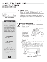
1.1 Terminals (J9)
Power Connection Terminals
PowerisprovidedfromtheNominal12Vdcauxiliaryoutputoftheburglarycontrolpanel.
OBSERVEPOLARITY(SeeFigure1andBacklitLogo)
Using18-22AWGwire,connectthe
communicator
terminal+12tothepositiveterminalonthe
control panel
auxiliary output
.
ConnectthecommunicatorterminalG(Ground)tothenegativeterminalonthecontrolpanelauxiliaryoutput.
Control Panel Standby Power
Duringapoweroutage,theiComSLdrawspowerfromthecontrolpanel’sbackupbattery.TheiComSLmustbe
included in the standby battery calculations for the control panel.
Zones 1-4
TerminalsZ1toZ3,G(Ground),Z4+andZ4-providefourzonestoconnecttoindividualrelayoutputson
thecontrolpanel.Zone4(Z4+andZ4-)canbeconnectedtothecontrolpanelbelloutput.SeeZone4Bell
Connection.
Figure 1: iComSL Series Communicator
RB
J8
J1
RESET
LOAD
S1
S2
S3
J9
system components

Digital Monitoring Products
iComSL
Series Universal Communicator Installation and Programming Guide
2
system components
Open-Collector Outputs
Thetwooutputs,terminalsO1andO2(seeFigure1),canbeprogrammedtoindicatetheactivityofthezones
orconditionsoccurringonthesystem.Open-Collectoroutputsdonotprovideavoltagebutinsteadswitch-to-
groundthevoltagefromanothersource.Maximumvoltageis30Vdc@50mA.Theoutputscanrespondtoanyof
the conditions listed below:
1) Activationbyzonecondition:Steady,Pulse,Momentary,orFollow
2) Communication
3) Armedareaannunciation
4) RemoteArmingOutput
Dialer Connection
Directlyconnectthetelcophoneline(tipandring)fromthecontrolpaneltotheiComSLSeriesUniversal
CommunicatorterminalR(Ring)andoneintoT(Tip)(SeeCIDDialerConnection).
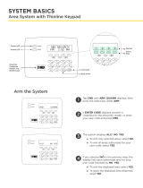
1.2 Programming Connection
A4-pinheader(PROG)isprovidedtoconnectakeypadwhenusingaDMP
Model330ProgrammingCable.Thisprovidesaquickandeasyconnection
for programming the
iComSL
SeriesUniversalAlarmCommunicator.After
programmingiscomplete,removethekeypad.
1.4 Tamper
ThetamperbuttonispressedwhenthecoveroftheiComSLSeries
Communicatorissecuredontotheenclosure.Whenthecoverisremoved,the
communicatorsendsaTamperTroublemessagetotheCentralStation.
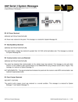
1.5 Reset Button
The Reset button is located on the right side of the circuit board and is used to
resetthecommunicatormicroprocessor.Afterresettingthe
communicator,
begin
programmingwithin30minutes.Ifyouwaitlongerthan30minutes,resetthe
communicator
again.
1.6 Load Button
The
iComSL
SeriesUniversalAlarmCommunicatorsoftwarecanbeupdated
viatheprogramming(PROG)header.Toupdatethecommunicatorwithanew
software version, complete the following steps at the protected premise:
1. ConnectaDMP399CablefromtheProgrammingHeadertotheserialportof
yourPCoperatingRemoteLinkandcontainingthecommunicatorRUle.
2. StartRemoteLinkandcreateoropentheaccountthatmatchesthe
communicator to be updated.
3. SettheConnectionInformationTypetoDirectwithabaudrateof38400and
choosetheappropriateCOMport.
4. SelectPanel>RemoteUpdate,thenselectthecorrectRUleforthe
communicator.
5. PressandholdtheLOADbutton,thenpressandreleasetheRESETbutton.
6. ReleasetheLOADbuttonandclick<Update>inRemoteLink.
7. Afterthesoftwareupdateiscompleted,removethe399cableandpresstheRESETbuttontoresumenormal
operation.
1.7 Backlit Logo
ThebacklitlogoindicatesthePowerandArmedstatusofthecommunicator.Dependingontheoperation,the
LEDdisplaysinRedorGreenaslistedinthetable.TheLEDindicatesthestatusofthesystembatteryand
primary power.
Color and Activity Operation
GreenSteady CommunicatorDisarmed,PrimaryPowerOK,BatteryOK
GreenBlinking CommunicatorDisarmed,PrimaryPowerOK,BatteryFault
NoLight CommunicatorDisarmed,PrimaryPowerFault,BatteryOK
RedSteady CommunicatorArmed,PrimaryPowerOK,BatteryOK
Red/GreenAlternate CommunicatorArmed,PrimaryPowerOK,BatteryFault
RedBlinking CommunicatorArmed,PrimaryPowerFault,BatteryOK
RB
J8
J1
RESET
LOAD
S1
S2
S3
J9
Figure 2: PROG Port Location
RB
J8
J1
RESET
LOAD
S1
S2
S3
J9
Figure 3: Tamper Location
RB
J8
J1
RESET
LOAD
S1
S2
S3
J9
Figure 4: Reset and Load
Button Location

iComSL
Series Universal Communicator Installation and Programming Guide Digital Monitoring Products
3
Mounting the iComSL Series Communicator
2.1 Selecting a Location
Install the communicator away from metal objects. DO NOT MOUNT THE iCOMSL SERIES COMMUNICATOR INSIDE
OR ON A CONTROL PANEL METAL ENCLOSURE (SeeFigure5).
Control Panel
Metal Enclosure
Figure 5: Suggested Mounting Locations
Figure 6: Mounting Screw Locations
Mounting Screw Locations
RB
J8
J1
RESET
LOAD
S1
S2
S3
J9
Figure 7: Wire Routing Options
RB
J8
J1
RESET
LOAD
S1
S2
S3
J9
RB
J8
J1
RESET
LOAD
S1
S2
S3
J9
MountingthecommunicatoronornearmetalsurfacesimpairsZ-Wavewirelessperformance.Theenclosurefor
the
c
ommunicatorshouldbemountedusingtheprovided#6screwsinthefourmountingholes(SeeFigure6).
Mounttheenclosureinasecure,dryplacetoprotectthecommunicatorfromdamageduetotamperingorthe
elements. It is not necessary to remove the PCB when installing the enclosure.
Wheninstallingcomponentwires,caremustbetakentorouteallwiresinsuchamannerthattheywillnot
interferewiththeTamperswitch(SeeFigure7).
InstallatIon

Digital Monitoring Products
iComSL
Series Universal Communicator Installation and Programming Guide
4
Applications
TheiComSLSeriesCommunicatorcanbeusedinavarietyofapplications:
3.1 CID
Dialer Connection
Directlyconnectthetelcophoneline(tipandring)fromthecontrolpaneltotheiComSLtocaptureContact
IDmessagesthatarebasedontheSIAcommunicationstandardDC-05-1999.09-DCS. These messages are
thenformattedintoaSerial3messageandsenttoaDMPModelSCS-1RorSCS-VRReceiver.Note:CIDDialer
ConnectioncannotbeusedwhenusingZone4BellConnection.
Figure 8: iComSL Series Wiring Diagram for Tip and Ring Connection
Use 18-22 AWG for
Power Supply connection
Z3 +
Z4 +
Z4 -
GND
12 VDC Aux. Output
+
-
Ground
Control Panel
The panel or separate power
supply must be 12 Volt Regulated
and Power Limited.
Z1 +
Z2 +
RESET
S1
LOAD
S2
BAT
PROG
S
N
+12 G Z1 Z2 Z4-Z4+GZ3 RTO2O1
RB
Normally Open
Common
Normally Closed
Normally Open
Common
Normally Closed
Normally Open
Common
Normally Closed
Normally Open
Common
Normally Closed
J8
J26
J9
S1
S2
S3
1k ohm
1k ohm
1k ohm
1k ohm
MODEL
iComSLC
Figure 9: iComSL Series Wiring Diagram for Zones 1 - 4
Use 18-22 AWG for
Power Supply connection
CONTROL PANEL TIP
CONTROL PANEL RING
12 VDC Aux. Output +
-
Ground
Control Panel
The panel or separate power
supply must be 12 Volt Regulated
and Power Limited.
Telephone
Jack
Connector
BELL -
BELL +
RESET
S1
LOAD
S2
BAT
PROG
S
N
+12 G Z1 Z2 Z4-Z4+GZ3 RTO2O1
RB
J8
J26
J9
S1
S2
S3
MODEL
iComSLC
3.2 Zones 1 - 4 Input Connection
ConnecteachburglarycontrolpanelrelayoutputtoaiComSLSeriesCommunicatorzone.Forprogramming
purposes,thezonenumbersare1-4.(SeeFigure9forwiringdetails).Anexampleofhowyoumightusethis
application:Youcanuseanormallyclosedoutputontheburglarycontrolpaneltoindicateaburglaryalarm.The
iComSLzoneshouldbeprogrammedwithazonenameandzonetypeofBurg.Whentheoutputonthecontrol
panelturnsonandtripstheiComSLzone,amessagewillbesenttoanSCS-1RorSCS-VRreceiveratCentral
Station.Youcouldusethezonenameprogrammingtodescribewhichcontrolpanelzoneindicatedaburglary.
Note:Zone4canonlybeusedasastandardinputzonewhennotprogrammedaszonetypeAuxiliary2(A2).See
Zone4BellConnection.
applIcatIons

iComSL
Series Universal Communicator Installation and Programming Guide Digital Monitoring Products
5
applIcatIons
3.3 Zone 4 Bell Connection
Zone4(Z4+andZ4-)canbeconnectedtothecontrolpanelbelloutput.Thiszonedetectsanalarmcondition
onthecontrolpanelbymonitoringthevoltageandcadencetimingofthebelloutput.SeeZone4BellCadence
InformationintheAppendixforcadencetiming.Toenablealarmdetectionoperation,Zone4BellConnection
mustbeprogrammedasZoneType(A2)inZoneInformationprogramming.ThetypeofCadencesenttothe
iComSLCommunicator,theZoneNumber,andtypeofmessagesenttotheSCS-1RorSCS-VRreceiverarelisted
below:
BELL CADENCE ZONE NUMBER TYPE OF MESSAGE
Steady ZONE 4 BURGLARY
Pulse or Temporal 3 ZONE 5 FIRE
Temporal 4 ZONE 6 EMERGENCY OR
CARBON MONOXIDE
Note:Zone5and6areautomaticallygeneratedbytheiComSL,usingZone4’sZonenametosendtotheCentral
Station.Zones5and6cannotbepreprogrammedinZoneInformation.
Note:CIDDialerConnectioncannotbeusedwhenusingZone4BellConnection.
Use 18-22 AWG for
Power Supply
connection
Z4 +
Z4 -
DMP Panel
MODEL iComSL
PROG
+12 G Z1 Z2 Z4-Z4+GZ3 RTO2O1
RB
J8
J9
S3
12 Vdc Aux. Output
+
-
BELL -
12 Vdc BELL +
Use 18-22 AWG for
Power Supply
connection
Z4 +
Z4 -
ADEMCO Panel
MODEL iComSL
PROG
+12 G Z1 Z2 Z4-Z4+GZ3 RTO2O1
RB
J8
J9
S3
12 Vdc Aux. Output
+
-
BELL -
12 Vdc BELL +
Use 18-22 AWG for
Power Supply
connection
Z4 +
Z4 -
NAPCO Panel
MODEL iComSL
PROG
+12 G Z1 Z2 Z4-Z4+GZ3 RTO2O1
RB
J8
J9
S3
12 Vdc Aux. Output
+
-
BELL -
12 Vdc BELL +
Use 18-22 AWG for
Power Supply
connection
Z4 -
DSC Panel
MODEL iComSL
PROG
+12 G Z1 Z2 Z4-Z4+GZ3 RTO2O1
RB
J8
J9
S3
12 Vdc Aux. Output
+
-
BELL -
12 Vdc BELL +
10k ohm
1k ohm
1k ohm
1k ohm
1k ohm
1k ohm
2.2k
ohm
Program Zone 4
DO - Alarm
AO - Alarm
Voltages above 1.4 Vdc
are considered Alarm
Voltages above 1.4 Vdc
are considered Alarm
Voltages above 1.4 Vdc
are considered Alarm
Voltages below 0.7 Vdc
are considered Alarm
Figure 10: Zone 4 Bell Connection

Digital Monitoring Products
iComSL
Series Universal Communicator Installation and Programming Guide
6
Remote Arming/Disarming
4.1 DMP Virtual Keypad App / Virtual Keypad Browser
UsingaSmartphonewiththeDMPVirtualKeypadApporusingacomputerwiththeVirtualKeypadBrowser
(www.myvirtualkeypad.com),youcanconnecttotheiComSLSeriesCommunicatortoarmAreas,turnOutputs
onandoff,andadd,editorremoveUsers.WhenusingtheiComSLCZ,youcancontrolZ-Wavedevices,Favorites
and Rooms.
Use 18-22 AWG for
Power Supply connection
O1
O2
12 Vdc Aux. Output
+
-
Control Panel
BAT
MODEL iComSL
PROG
+12 G Z1 Z2 Z4-Z4+GZ3 RTO2O1
RB
GND
Zone 1
Zone 2
Control Panel EOL resistor
Figure 11: Virtual Keypad Application can be used to access the iComSL Series Communicator.
Figure 12: Burglary control panel zones connected to the iComSL outputs
to arm and disarm the burglary control panel.
AburglarycontrolpanelzonemaybeprogrammedasanarmingzoneandconnectedtoaiComSLoutput(O1or
O2)(SeeFigure12).ProgramtheoutputnumberinArmedOutputorRemoteArmingOutputinOutputOptions
oftheiComSL(See12.4ArmedOutputor12.5RemoteArmingOutput).TheIComSLCommunicatoroutput
connectionscanbeusedwithanyoftheapplicationslistedinApplicationsSection.
remote armIng/dIsarmIng

iComSL
Series Universal Communicator Installation and Programming Guide Digital Monitoring Products
7
Programming the
iComSL
Series Universal Alarm Communicator
5.1 Before You Begin
Before starting to program, we recommend you read through the contents of this guide. The information in this
documentallowsyoutoquicklylearntheprogrammingoptionsandoperationalcapabilitiesofthe
iComSL
Series
UniversalAlarmCommunicator.
AfterthisIntroduction,theremainingsectionsdescribethefunctionsofeachprogrammingmenuitemsalong
with their available options. The
communicator
contains all of its programming information in an on-board
processor and does not require an external programmer.
In addition to this manual, you should also be familiar with the following
documents:
• iComSL
SeriesUniversalAlarmCommunicatorUserSheet(LT-1349)
• iComSL
SeriesUniversalAlarmCommunicatorProgrammingSheet(LT-1411)
Programming Information Sheet
Included with each communicatoraretheProgrammingSheets.Thesesheetslistthevariousoptionsavailable
for programming the
communicator
.Beforestarting,completelylloutthesheetswiththeprogrammingoptions
you intend to enter into the
communicator
.
Having completed the programming sheets available while entering data helps to prevent errors and can shorten
the length of time you spend programming. Completed sheets also provide you with an accurate account of the
communicator
’sprogramyoucankeeponleforfuturesystemserviceorexpansion.
The remainder of the Introduction explains starting and ending a programming session.
5.2 Getting Started
Initializing the
iComSL
Series
Whenprogramminga
communicator
forthersttimeorrewritingtheentireprogramofanexisting
communicator, use the Initialization functiondescribedinSection6.Initializingclearsthecommunicator’s
memoryofanyolddataandsetsthehighestnumberedusernumbertousercode99.
Accessing the Programmer
To access the programmer function of the
communicator
:
1. ConnectthekeypadtothePROGheader
2. Press and release the reset button.
3. Enterthecode6653(PROG).
4. Thekeypaddisplays:PROGRAMMER.
5.3 Programming Menu
Youarenowreadytostartprogrammingthe
iComSL
SeriesUniversalAlarmCommunicator.PressingtheCOMMAND
keyscrollsyouthroughtheprogrammingmenuitemslistedbelow.
Menu Item Section in This Manual Menu Item Section in This Manual
Initialization 6 Output Options 12
Communication 7 Area Information 13
Messaging Setup 8 Zone Information 14
Remote Options 9
Stop
15
System Reports 10 Set Lockout Code 16
System Options 11
Toselectasectionforprogramming,pressanySelectkeywhenthenameofthatsectiondisplaysonthekeypad.
The detailed instructions for each programming step are found in this guide.
5.4 Reset Timeout
The
iComSL
SeriesUniversalAlarmCommunicatorhasafeaturethatrequiresyoutoentertheProgrammerwithin
30minutesofresettingthecommunicator.After30minutes,ifyouattempttoprogrambyenteringthe6653
(PROG)code,thekeypaddisplays:RESET PANEL.Youmustresetthe
communicator
and enter the program code
withinthenext30minutes.
IfyouarealreadyintheProgrammeranddonotpressanykeysontheprogrammingkeypadfor30minutes,the
communicator
terminatesprogramming.Alldataentereduptothatpointissavedinthecommunicatormemory.
Using the STOP function disarms all areas:Toexitthecommunicator’sProgrammeryoumustusetheSTOP
function. The STOP optionisthesecondtothelastoptioninprogramming.TheStopfunctiondisarmsallareas.
TheprogrammingsessionisthenterminatedandthekeypadreturnstotheStatusListorMainScreen.
programmIng

Digital Monitoring Products
iComSL
Series Universal Communicator Installation and Programming Guide
8
programmIng
5.5 Special Keys
Thefollowingspecialkeys/areasarecommontoallDMPkeypads.
COMMAND (CMD) Key
PressingtheCOMMANDkeyallowsyoutogoforwardthroughtheprogrammingmenuandthrougheachstepofa
programmingsection.Asyougothroughtheprogramming,thekeypaddisplayshowsanycurrentprogramming
alreadystoredinthecommunicatormemory.Ifnochangeisrequiredforanoption,presstheCOMMANDkeyto
advance to the next step.
TheCOMMANDkeyisalsousedtoenterinformationintothecommunicator’smemorysuchasanIPaddressor
zonenames.PresstheCOMMANDkeyafterenteringinformation.
Back Arrow (<—) Key
UsetheBackArrowkeytobackuponestepwhileprogramming.TheBackArrowkeyisalsousedwhenanerroris
madewhileenteringinformation.PresstheBackArrowkeyoncetoerasethelastcharacterentered.
Select Keys/Areas
ThetoprowofkeysarecalledtheSelectkeysonThinline,andAqualitekeypadsorSelectAreasonGraphic
Touchscreenkeypads.EachtimeyouneedtopressaSelectkey,thekeypaddisplaysthefunctionoroptions
aboveoneofthekeysorintheSelectArea.DisplayingchoicesaboveindividualSelectkeysorinSelectAreas
allowsthemtobeusedformanydifferentapplications.Forexample,youcanenterAMorPMwhenprogramming
the automatic test time or answer YES or NO for a system option.
Duringprogramming,theSelectkeys/areasalsoallowyoutochangeinformationcurrentlyincommunicator
memorybypressingtheappropriateSelectkeyunderoronthedisplay.Youthenenterthenewinformationusing
thekeypaddataentrydigitkeys.
Whentherearemorethanfourresponseoptionsavailable,presstheCOMMANDkeytodisplaythenextoneto
fouroptions.PressingtheBackArrowkeyallowsyoutoreviewthepreviousfourchoices.
TheSelectkeys/areasarealsousedforchoosingasectionfromtheprogrammingmenu.PressanySelectkeyor
touchtheSelectAreawhentheprogrammingsectionnameyouwantdisplays.
On Thinline and Aqualite keypads,wheninstructedtopresstherstSelectkey,pressthefarleftSelectkey;
thesecondSelectkeyisthesecondfromtheleft;thirdSelectkeyissecondfromtheright;andthefourthSelect
keyisthefarrightkey.SeeFigure13.
On Graphic Touchscreen Keypads,wheninstructedtopresstherstSelectkey,touchSelectArea1;thesecond
SelectkeytouchSelectArea2;thirdSelectkeytouchSelectArea3;andthefourthSelectkeytouchSelect
Area4.SeeFigure14.
5.6 Entering Alpha Characters
Someoptionsduringprogrammingrequireyoutoenteralphacharacters.Toenteranalphacharacter,pressor
touchthekeythathasthatletterwrittenbelowit.Thekeypaddisplaysthenumberdigitofthekey.Next,press
theSelectkey/areathatcorrespondstothelocationoftheletterunderthekey.PressingadifferentSelectkey/
areachangestheletter.Whenanotherdigitkeyispressed,thelastletterdisplayedisretainedandtheprocess
starts over.
Figure 13: Thinline/Aqualite Select Keys Figure 14: Graphic Touchscreen Select Areas
First Letter
Second Letter
Third Letter
Special Character
(CBA
32-Character Display
Select Area 1
Select Area 3
Select Area 2
Select Area 4

iComSL
Series Universal Communicator Installation and Programming Guide Digital Monitoring Products
9
programmIng
5.7 Entering Non-Alpha Characters
Toenteraspaceinanalphaentry,pressthe9digitkeyfollowedbythethirdSelectkey/area.Thethree
charactersonthe9digitkeyareY,Z,andspace.Youcanalsoenterthefollowingcharacters:–(dash),.(period),
*(asterisk),and#(poundsign)usingthe0(zero)keyandthefourSelectkeys/areasfromlefttoright.For
example,toentera–(dash),pressthe0(zero)keyandthentheleftSelectkey/area.Adashnowappearsinthe
keypaddisplay.ThetablebelowshowsthecharacterlocationsforDMPkeypads.
Key Number Select Key 1 Select Key 2 Select Key 3 Select Key 4
1 A B C (
2 D E F )
3 G H I !
4 J K L ?
5 M N O /
6 P
Q
R &
7 S T U @
8 V W X ,
9 Y Z space _
0 - . * #
5.8 Keypad Displays Current Programming
Eachprogrammingpromptdisplayedatthekeypadshowsthecurrentlyselectedoptioninthecommunicator
memory.Theseoptionsareeithershownasanumber,ablank,oraNO or YES.Tochangeanumberorblanktoa
newnumber,pressanytoprowSelectkeyortouchanySelectArea.Thecurrentoptionisreplacedwithadash.
Pressthenumber(s)onthekeypadyouwanttoenterasthenewnumberforthatprompt.Itisnotnecessaryto
enternumberswithleadingzeros.Thecommunicatorautomaticallyrightjustiesthenumberwhenyoupress
theCOMMANDkey.
To change a programming prompt that requires a NO or YESresponse,presstheSelectkeyortouchtheSelect
Areafortheresponsenotselected.
For example, if the current prompt is selected as YES and you want to change it to NO,onThinlineorAqualite
keypadspressthethirdtoprowSelectkey.OnGraphicTouchscreenkeypadstouchSelectArea3.Thedisplay
changes to NO.PresstheCOMMANDkeytodisplaythenextprompt.

Digital Monitoring Products
iComSL
Series Universal Communicator Installation and Programming Guide
10
Initialization
6.1 Initialization
This function allows you to set the communicator’sprogrammedmemorybacktothe
factory defaults in preparation for system programming.
AfteryouselectYEStoclearasectionofmemory,thecommunicatorasksifyouaresure
you want to clear the memory. This is a safeguard against accidently erasing part of your
programming.NomemoryisclearedfromtheprogramminguntilyouanswerYEStothe
SURE?YES NOprompt.
6.2 Clear All Codes
NOleavesexistingcodesintact.
YESclearstheusercodememoryandassignstheusercodenumber99touser20.
6.3 Clear All Schedules
NO -Leavesexistingschedulesintact.
YES - Clears all schedules from the programming.
6.4 Clear Events
NO leaves existing event memory intact.
YES clears all event memory currently held in the communicator’sDisplayEventsbuffer.
6.5 Clear Zone Programming
NO leaves existing zone information intact.
YES setsallzonesinthesystemto*UNUSED*
6.6 Clear Communication
NO - Leavesexistingcommunicationprogrammingintact.
YES - Clears communication to factory defaults.
6.7 Set to Factory Defaults
NO leaves the remainder of the existing communicator programming intact.
YES sets the communicatorprogrammingbacktofactorydefaultselectionsandclears
allZ-WavedeviceprogrammingandFavoritesfromthecommunicator.SelectingYES
does not clear the event memory, zone, user code information, or schedules.
INITIALIZATION
CODES? NO YES
SURE? YES NO
SCHEDS? NO YES
SURE? YES NO
EVENTS? NO YES
SURE? YES NO
ZONES? NO YES
SURE? YES NO
COMMS? NO YES
SURE? YES NO
DEFAULTS? NO YES
SURE? YES NO
CODES?
NO YES
SCHEDS? NO YES
For each section of the panel program you can
initialize, a NO or YES option is provided.
Selecting YES advances you to
a confirmation prompt.
If you select YES, the panel initializes that section of
the program and advances you to the next prompt.
If you select NO, the panel advances you to the next
section prompt but does not initialize that section of
the program.
SURE? YES NO
Selecting NO
advances you to
the next prompt.
InItIalIzatIon

iComSL
Series Universal Communicator Installation and Programming Guide Digital Monitoring Products
11
Communication
7.1 Communication
TheCommunicationsectionallowsyoutocongurethecommunicationsettingsforthe
iComSL
Communicator.AfterchoosingtheCommunicationType,continuethroughthe
list of options.
7.2 Account Number
Entertheaccountnumbersenttothereceiver.
Therangeofaccountnumbersis1to65535.Foraccountnumbersoffourdigitsorless,
you do not have to enter leading zeros. The
c
ommunicatorautomaticallyrightjusties
the account number.
7.3 Transmission Delay
Enterthenumberofseconds(15to45seconds)thecommunicator waits before sending
burglaryalarmreportstothereceiver.Enter0(zero)todisablethisfunction.The
defaultis0.
7.4 Communication Type
The
c
ommunicatorusesNetworkcommunicationtoDMPModelSCS-1RorSCS-VR
Receivers.
7.5 Test Time
PressCOMMANDtodisplaytheTestTime.Enterthetimeofdaythecommunicator sends
thetestreporttotheSCS-1RorSCS-VRReceivers.Useentriesbetween12:00to11:59
andthenchooseAMorPM.
7.6 Test Days
Enterhowoftenthepaneltestreportissenttothereceiver.Enterfrom1to60days.
Enterzerotodisablethetestreport.Defaultis1(one)day.Theseoptionsonlydisplayif
a test time is entered.
7.7 Check-in Minutes
Check-inreportsareamethodofsupervisingthepanelforcommunicationwiththe
receiver.
Enterthenumberofminutesbetweencheck-inreports.Selectfrom0or3-240minutes.
Enter0(zero)todisablethecheck-inoption.Defaultis0.
7.8 Fail Time
FailTimeallowstheSCS-1RorSCS-VRreceivertomissadenednumberofcheck-ins
before logging that the panel is missing. For example, if NET CHECKIN is20andFAIL
TIMEis30,theSCS-1RreceiveronlyindicatesaPanelNotRespondingafter30minutes.
The FAIL TIME must be equal to or greater than the NET CHECKIN minutes: If the
CHECKINis20minutes,theFAIL TIME mustbe20ormore.ThemaximumFAIL TIME is
240minutes.Selectfrom0or3-240minutes.ThedefaultFAIL TIME is240minutes.
7.9 Receiver 1 Programming
Allowsyoutosettheoptionsfortherstreceiverthe
c
ommunicator attempts to
contact when sending reports. The
communicator
supports communication to two
receivers.
7.10 Alarm Reports
YESenablesAlarm,AlarmRestoral,ExitError,andSystemRecentlyArmedreportstobe
senttothisreceiver.DefaultisYES
7.11 Supervisory/Trouble Reports
YESenablesSupervisory,Trouble,TroubleRestoral,ForceArmed,andFaultreportstobe
senttothisreceiver.DefaultisYES.
7.12 Opening/Closing and User Reports
YESenablesOpening/Closing,ScheduleandCodeChanges,andBypassreportsbyuserto
besenttothisreceiver.DefaultisYES.
7.13 Test Report
EnterYEStoenabletheRecallTestreporttobesenttothisreceiver.
7.14 First IP Address
Entertherst(primary)IPaddresswherethe
c
ommunicator sends messages. The IP
addressmustbeuniqueandcannotbeduplicatedonthenetwork.Enterall12digitsand
leaveouttheperiods.Forexample,enterIPaddress192.168.0.250as192168000250.
The periods display automatically.
7.15 First IP Port
EntertherstIPportnumbertobeusedinconjunctionwiththeFirstIPAddress.TheIP
portidentiestheportusedtocommunicatemessagestoandfromthecommunicator.
ThedefaultIPPortsettingis2001.
COMMUNICATION
ACCOUNT NO:
XMIT DELAY: 0
COMM TYPE: CELL
CELL TST DAYS: 1
CHECKIN: 0
FAIL TIME: 240
RECEIVER 1 PROG
ALARM NO YES
SPV/TRBL NO YES
O/C USER NO YES
TEST RPT NO YES
FIRST IP ADDR
000.000.000.000
FIRST IP PORT
2001
TEST TIME
00:00 AM
communIcatIon

Digital Monitoring Products
iComSL
Series Universal Communicator Installation and Programming Guide
12
communIcatIon
7.16 Second IP Address
EnterthesecondIPaddresswherethecommunicator sendsnetworkmessages.TheIP
Addressmustbeuniqueandcannotbeduplicatedonthenetwork.Enterall12digitsand
leaveouttheperiods.Forexample,enterIPaddress192.168.0.250as192168000250.
The periods display automatically.
7.17 Second IP Port
EnterthesecondIPportnumbertobeusedinconjunctionwiththeSecondIPAddress.
TheIPportidentiestheportusedtocommunicatemessagestoandfromthe
communicator.ThedefaultIPPortsettingis2001.
7.18 Receiver 2 Programming
Allowsyoutosettheoptionsforthesecondreceiverthecommunicator attempts to
contact when sending reports. The communicator supports communication to two
receivers.IfyouselectYESforanyoftheReceiver2options,youmusthaveatleastone
IPaddressprogrammedinReceiver2programming.Receiver2defaultsaresettoNO.
7.19 Alarm Reports
YESenablesAbort,Alarm,AlarmRestoral,AlarmBellSilenced,Ambush,ExitError,and
SystemRecentlyArmedreportstobesenttothisreceiver.DefaultisNO.
7.20 Supervisory/Trouble Reports
YESenablesSupervisory,Trouble,TroubleRestoral,ForceArmed,LatetoClose,and
Faultreportstobesenttothisreceiver.DefaultisNO.
7.21 Opening/Closing and User Reports
YESenablesOpening/Closing,ScheduleandCodeChanges,andBypassreportsbyuserto
besenttothisreceiver.DefaultisNO.
7.22 Test Report
YESenablestheRecallTestreporttobesenttothisreceiver.DefaultisNO.
7.23 First IP Address
Entertherst(primary)IPaddresswherethe
c
ommunicator sends messages. The IP
addressmustbeuniqueandcannotbeduplicatedonthenetwork.Enterall12digitsand
leaveouttheperiods.Forexample,enterIPaddress192.168.0.250as192168000250.
The periods display automatically.
7.24 First IP Port
EntertherstIPportnumbertobeusedinconjunctionwiththeFirstIPAddress.
TheIPportidentiestheportusedtocommunicatemessagestoandfromthepanel.
ThedefaultIPPortsettingis2001.
7.25 Second IP Address
EnterthesecondIPaddresswherethecommunicator sendsnetworkmessages.TheIP
Addressmustbeuniqueandcannotbeduplicatedonthenetwork.Enterall12digitsand
leaveouttheperiods.Forexample,enterIPaddress192.168.0.250as192168000250.
The periods display automatically.
7.26 Second IP Port
EnterthesecondIPportnumbertobeusedinconjunctionwiththeSecondIPAddress.
TheIPportidentiestheportusedtocommunicatemessagestoandfromthepanel.
ThedefaultIPPortsettingis2001.
SECOND IP ADDR
000.000.000.000
SECOND IP PORT
2001
RECEIVER 2 PROG
ALARM NO YES
SPV/TRBL NO YES
O/C USER NO YES
TEST RPT NO YES
FIRST IP ADDR
000.000.000.000
FIRST IP PORT
2001
SECOND IP ADDR
000.000.000.000
SECOND IP PORT
2001

iComSL
Series Universal Communicator Installation and Programming Guide Digital Monitoring Products
13
messagIng setup
Messaging Setup
8.1 Messaging Setup
This section allows you to enter the information needed to send and receive messages
directlytoandfromthepanelviaEmailusingnetworkcommunication.TheDestination
addressesallowupto48characterstobeentered.SystemNameisdisplayedwithinitial
caps.
The transmitted messages are:
•ZoneAlarmsbyZoneName
•ZoneTroublesbyZoneName
•ZoneBypassbyUser
•Arming(Closings)byUser
•Disarming(Openings)byUser
•ACPowerTroubleandRestoral
•SystemLowBattery
•CancelbyUser
8.2 Enable Messaging
SelectYEStoallowthepaneltosendmessagestothreeprogrammeddestinations.
DefaultisNO.
8.3 System Name
Enterauniq
ue name for the communicator. The communicator name is used as the
sender of the message. The text entered is displayed w
ithinitialcaps.Ifthiseldisleft
blank,thecommunicatoraccountnumberissent.
8.4 Destination 1
EntertherstEmailaddresswheremessageswillbesent.Themessagecanbesentto
anydevice(computer,cellphone,tablet)aslongasavalidEmailaddressisentered.
WhenenteringEmailaddresses,pressthe7digitkeyfollowedbythefourthSelectKey
toaddthe@symbolandthe9digitkeyfollowedbythefourthSelectKeytoaddthe_
symbol.SeetheEnteringNon-AlphaCharacterssectionforadditionalsymbols.
8.5 Destination 1 User Number
Enterauser’susernumberfromthisaccount.Thisoptionisusedwhensendingcommands
suchasarmingordisarmingtotheiComSLusingEmail.Theusernumbermusthavethe
authoritytoperformthecommands.Entering0(zero)disablesthisoption.Defaultis0.
8.6 Destination 2
EntertheseconddestinationEmailaddress.
8.7 Destination 2 User Number
Entertheuser’sUserNumberforarming/disarmingauthorization.
8.8 Destination 3
EnterthethirddestinationEmailaddress.
8.9 Destination 3 User Number
Entertheuser’sUserNumberforarming/disarmingauthorization.
8.10 O/C Email
SelectYEStoallowthepaneltosendOpeningandClosingreportsviaEmail.
DefaultisNO.
8.11 Monthly Limit
ThisnumberlimitsthemonthlyincomingandoutgoingEmailmessagesallowedtobe
sent or received by the panel.
ApaneleventthatcausesmessagestobesenttodestinationEmailaddressesiscounted
towardsthepanel’smonthlylimit.Forexample,ifanalarmmessageissenttoanEmail
address,atotalof2messagesarecountedtowardsthemonthlylimitforthepanel.The
limitisresetatmidnightonthe14thofeverymonth.Rangeisfrom0to999.When0is
entered, there is no limit on the number of messages able to be sent or received by the
panel.Defaultis0.
TheremainingoptionsallowtheEmailservertobeselectedbytheinstallingdealer.
TypicallythiswillbetheEmailserviceprovidedbytheinstallingdealer.Thisallows
opportunity for additional services to be provided to the end user.
MESSAGING SETUP
DESTINATION 1
-
DESTINATION 2
-
DESTINATION 2
USER NUMBER:
0
DESTINATION 3
-
SYSTEM NAME
-
ENABLE MESSAGING
NO YES
DESTINATION 1
USER NUMBER:
0
O/C EMAIL NO YES
DESTINATION 3
USER NUMBER:
0
MONTHLY LIMIT: 0

Digital Monitoring Products
iComSL
Series Universal Communicator Installation and Programming Guide
14
messagIng setup
8.12 SMTP Server
EntertheSMTP(SimpleMailTransferProtocol)Servername.TheSMTPEmailserveris
responsibleforsendingtheEmailtoitsdestination.AnexampleSMTPEmailservername
is:mail.somedomain.com.ThedomainshouldbetheEmailserverthatwillprovide
Emailsupportforyouralarmcustomers.
8.13 SMTP Server Port
TheSMTPserverportnumberistheportthatthepanelusestoinitiateaTCPconnection
withtheEmailserver.Thedefaultportis25.
8.14 SMTP Username
MostSMTPserversrequireausernametosendEmail.ThiswillbesenttotheSMTP
serverinconjunctionwiththeSMTPPasswordtoprovideEmailauthenticationtothe
server.
8.15 SMTP Password
MostSMTPserversrequireapasswordtosendEmail.ThiswillbesenttotheSMTPserver
inconjunctionwiththeSMTPUsernametoprovideEmailauthenticationtotheserver.
8.16 From Email Address
EntertheEmailaddressonlewiththeEmailservice.ThiswillshowupintheEmail
messagesasthesender’saddress.
SMTP SERVER
-
SMTP PORT: 25
SMTP USERNAME
-
SMTP PASSWORD
-
FROM EMAIL
-
/