Page is loading ...

INSTALLATION GUIDE
iCOM
sl
™ Network Alarm Communicator
Description
The iCOMsl™ Network Alarm Communicator allows any alarm panel to communicate alarm and system messages
over a full-time Internet, LAN, or WAN Ethernet network connection. The iCOMsl transmits messages in Serial 3
format to the SCS-1R Receiver and to Remote Link or System Link software. Easily program the iCOMsl with any DMP
32-character LCD keypad.
This guide begins with an overview of the iCOMsl operation and wiring. The next section discusses connecting the
iCOMsl to the congurations listed below. The last section covers programming the iCOMsl for operation.
The iCOMsl can function in two modes:
• KeypadBusMode: The iCOMsl connects to the keypad bus of an XRSuper6, XR20, or XR40 Command Processor™
Panel installed in a DMP Model 349 Medium enclosure to provide network communication for all panel events to
the central station. Also, in Keypad Bus Mode, a Communication Fail Output is provided.
• InputMode: In this mode the iCOMsl provides six programmable zones and six open collector outputs. Input
mode allows the iCOMsl to operate as a slave network communicator that communicates alarm messages from
any security and re alarm panel.
The iCOMsl is available in different congurations for specic operation:
• iCOMsl-XR/AA: Provides Standard Line Security network communication for DMP XRSuper6, XR20, or XR40
Command Processor™ Panels installed in a DMP Model 349 Medium enclosure.
• iCOMsl-12V/AA: Provides Standard Line Security network communication for non-DMP 12 VDC commercial
burglary panels.
• iCOMsl-12V/NACT: Provides 12 VDC network communication for non-DMP FACP installations.
• iCOMsl-24V/NACT: Provides 24 VDC network communication for non-DMP FACP installations.
iCOM
sl
LED Indicators
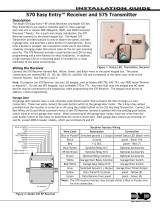
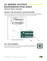
Figure 1 shows the iCOMsl PCB layout and identies the location of each LED. The tables below describe the LED
indicators and their operation.
Network and Error LEDs
The Network and Error LEDs are located near the Output Header.
LED Operation/Color Denition
LINK(LNK) Steady Green Communication link to network is okay.
ACTIVE(ACT) Flashing Yellow Indicates activity on the network.
E-2(Error2) Steady On
iCOMsl is connected to a network with a
duplicate IP address or does not detect a
network connection when powered up.
E-1(Error1)
Blinks Once
iCOMsl is connected to a network with a
duplicate IP address.
Blinks Six Times
iCOMsl is programmed with an IP address
and does not detect a network connection
when it is powered up.
Communication LEDs
Two pairs of Transmit and Receive Communication LEDs are located to the right
of the J2 and J3 headers. The pair to the right of J2 header indicate keypad
communication. The pair to the right of J3 header indicate panel communication.
LED Operation/Color Denition
Xmit(Transmit) Flashing Yellow
iCOMsl is transmitting data to the
keypad (J2) or to the panel (J3).
Rcv(Receive) Flashing Yellow
iCOMsl is receiving data from the keypad
(J2) or from the panel (J3).
Figure1:iCOM
sl
PCB
Power
Network
E1 E2 ACT LNK
RJ-45 8-pin
modular jack
J1
PowerProgramming
J3
Panel
Stand-offs
Keypad
J2
Rcv
Xmit
iCOM
SL
TM
Zone
Header
Output
Header
Pin 1
Pin 1
Black
Red
Black
Red
Rcv
Xmit

Digital Monitoring Products iCOMsl Installation Guide
2
Zone Wiring
When operating in input mode the iCOMsl offers six ungrounded,
non-powered zones. Connect each iCOMsl zone to an individual
output on the panel and cap unused wires on the zone harness.
Use 1k EOL resistors on each zone. Wire colors for the 12-wire
zone harness are detailed in Figure 2.
Note: When an iCOMsl is installed with an XRSuper6, XR20, or
XR40 panel in a DMP Model 349 Medium enclosure, the zone wiring
option is not available.
Output Wiring
The iCOMsl provides six programmable switched ground outputs
rated for a maximum 30 VDC at 50mA each. Outputs on the
iCOMsl can be used in several different ways to provide backup
local annunciation of panel zones or notication of iCOMsl
communication failure. See Figure 2 for the 7-wire harness
colors.
All outputs are for supplemental use with UL listed equipment
only. All wiring for these outputs is restricted to the same room.
Note: When an iCOMsl is installed with an XRSuper6, XR20, or XR40 panel, the output wiring option is not available.
Special Zone Types
The iCOMsl offers special zones types not offered by other DMP Command Processor™ panels.
Open/Close Zones
Open/Close zones allow the iCOMsl to send opening and closing messages. Open/Close zones do not trigger alarm
outputs, nor do they arm or disarm zones. When an Open/Close zone shorts, the iCOMsl reports a Closing message
to the central station. When an Open/Close zone returns to a normal state, the iCOMsl reports an Opening message
to the central station. Open/Close zones are typically attached to the panel’s armed output or used in conjunction
with an Enable zone, as shown in Figure 3.
Enable Zones
All zones on the iCOMsl are in an always armed state. Enable zones are provided as a way to disable specic zones.
Any of the six zones may be designated as an Enable zone. Programming an Enable zone allows that zone to serve as
a switch for all zones above it, until the next Enable zone.
Enable zones must be tripped (open or shorted) before zones with a higher number can transmit a message. Enable
zones may be tripped (open or shorted) in a number of different ways, such as Communication Fail Output or a
keyswitch, so the zones above it
can transmit messages.
For example, if zone 2 is an Enable
zone and it is connected to the
Communication Fail Output on the
panel, the zones on the iCOMsl
with a higher zone number function
only when communication on the
panel fails. Zone 1 is always active
because it is not controlled by the
Enable zone on zone 2. You may
use 24-hour type zones, such as
Fire, panic, or supervisory zones,
on Zone 1. In this example, zones
3 through 6 are controlled by the
Enable zone, allowing backup
network communication for up to
four zones. See Figure 3.
Burglary/Fire Zones
For detailed Burglary/Fire Zone
type conguration, refer to the
Appendix later in this document.
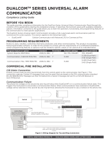
Figure2:OutputandWiringHarness
Zone
Harness
WR-0225
Zone 3 - : Orange/White
Zone 4 - : Yellow/White
Zone 3 +: White/Orange
Zone 5 +: White/Green
Zone 1 +: White/Brown
Zone 1 - : Brown/White
Zone 2 +: White/Red
Zone 2 - : Red/White
Zone 6 +: White/Violet
Zone 6 - : Violet/White
Zone 4 + : White/Yellow
Zone 5 - : Green/White
Output
Harness
WR-0224
Output 1: Brown
Output 2: Red
Output 3: Orange
Output 4: Yellow
Output 5: Green
Output 6: Violet
Ground: Black
Use UL Listed DMP Model 310
1k EOL resistors on each zone.
To Network
J1
Zone
Header
Output
Header
1k EOL
1k EOL
1k EOL
1k EOL
1k EOL
iCOM
TM
To panel outputs
Pin 1
Pin 1
1k EOL
+
_
J3
To Power
Maximum zone line impedence 100 Ohms
Ground fault detected at 1980 Ohms or less
{
Zone 1
always active
In this configuration, Zone 2 is connected to the Communication
Fail Output on the panel, allowing the iCOM
SL to provide backup
communication for the panel.
Zones 3 through 6 are connected to outputs on the panel and
are active only when the Enable zone is triggered by the panel's
Communication Fail Output.
Enable Zone
To Communication Fail Output on panel
J2
Use DMP Model 310 1k EOL resistors on each zone.
Z1 Z2 Z3 Z4 Z5 Z6 1 2 3 4 5 6
s
= Supervised
s s s s s s s s s s s s
Figure3:SampleCongurationforEnableZones

iCOMsl Installation Guide Digital Monitoring Products
3
iCOM
sl
-XR/AA Installation
This iCOMsl conguration is designed to provide Standard Line Security network communication for DMP XRSuper6,
XR20, or XR40 Command Processor™ Panels installed in a DMP Model 349 Medium enclosure.
What is Included
• iCOMsl Network Alarm Communicator
• Two WR-0126 4-wire harnesses
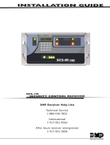
Wiring to XRSuper6, XR20, or XR40 Panels
Use these directions when wiring the iCOMsl to XRSuper6 (rmware version 204 or higher), XR20 (rmware version
203 or higher), and XR40 (rmware version 203 or higher) panels. Refer to Figure 4 and the XRSuper6/XR20/XR40
Installation Guide (LT-0624) for complete wiring and installation instructions for the panel.
1. Snap the iCOMsl onto the three hole pattern on the right side of the medium enclosure.
2. Connect one supplied WR-0126 4-wire harness to the J3 Panel Header on the iCOMsl.
3. Connect the other end of the WR-0126 4-wire harness to the J8 Programmer Header on the panel.
4. Connect an Ethernet cable from the network to the 8-pin modular connector (J1) on the iCOMsl.
5. Use the second WR-0126 4-wire harness to connect a DMP LCD keypad to the iCOMsl J2 Keypad Header for
programming.
J1: Network
J2: Keypad
Programmer
Header
J3: Panel
Header
Black
Red
Power limiting
wire routing
iCOM
SL
Yellow
Green
J16
Reset Jumper
J8
Programmer
Header
XRSuper6, XR20, or XR40
Command Processor™ Panel
Figure4:XRSuper6,XR20,orXR40Wiring
iCOM
sl
-12V/AA Installation
This iCOMsl conguration is designed to add Standard Line Security network communication to non-DMP 12 VDC
commercial burglary panels.
What is Included
• iCOMsl Network Alarm Communicator
• One 350D Mounting Plate
• One 377 Trouble Annunciator with Legend
• One 572 Remote Indicator LED
• Six 1k Ohm EOL resistors
• One WR-0203 2-wire power harness
• Two WR-0126 4-wire harnesses
• One WR-0225 12-wire zone harness
• One WR-0224 7-wire output harness
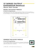
Wiring to Non-DMP 12 VDC Burglary Panels
Use these directions when wiring the iCOMsl to a UL listed non-DMP 12 VDC commercial burglary panel. The 350D
Mounting Plate with the iCOMsl and 377 Annunciator mount into the burglary panel enclosure or in a separate
enclosure listed for commercial burglary such as a Model 350. Refer to Figure 5 and the specic panel installation
document for complete wiring and installation instructions.

Digital Monitoring Products iCOMsl Installation Guide
4
1. Snap the iCOMsl standoffs onto the three hole pattern on one side of the 350D Mounting Plate.
2. Snap the included two standoffs onto the 377 Annunciator Module. Snap the 377 and mounted standoffs onto
the two hole pattern on the other side of the same 350D Mounting Plate as the iCOMsl.
3. Remove the nut from the 377 Red Trouble Silence button. Place the 377 Legend over the LEDs and Trouble
Silence button. Reinstall the nut to hold the legend in place.
4. Next to the connector at one end of one WR-0126 4-wire harness, cut the Red, Yellow, and Black Wires.
Plug the connector with the Green wire onto the iCOMsl J2 Header.
Plug the connector at the other end onto the 377 Module J1 Header.
5. Connect the Black wire cut end to the panel 12 VDC Aux. Output negative terminal.
Connect the Red wire cut end to the panel 12 VDC Aux. Output positive terminal.
Connect the Yellow wire cut end to the iCOMsl Output 1 Brown wire.
6. Plug the WR-0203 2-wire power harness connector onto the iCOMsl J3 Header.
7. Connect the WR-0203 2-wire power harness Black wire to the panel 12 VDC Aux. Output negative terminal.
Connect the WR-0203 2-wire power harness Red wire to the panel 12 VDC Aux. Output positive terminal.
8. Mount the 572 Remote Indicator LED.
Connect the White wire from the 572 LED to the iCOMsl Output 2 Red wire.
Connect the Red wire from the 572 LED to the panel 12 VDC Aux. Output positive terminal.
9. Wire iCOMsl zones 1, 2, and 3 to burglary panel outputs as shown using 1k Ohm EOL resistors.
10. Connect an Ethernet cable from your network to the 8-pin modular connector (J1) on the iCOMsl.
350D
Mounting
Plate
377
J1
To
Network
J1
Zone
Header
Output
Header
iCOM
To
Power
J3
J2
Trouble Annunciator Module
NORMAL
TROUBLE
SILENCE
COMMUNICATION
TROUBLE
Z1+
Z1-
12 VDC Aux. Output
Normally Open
Common
Normally Closed
Normally Open
Normally Open
Common
Common
Normally Closed
Normally Closed
†{
Z2+
Z2-
Z3+
Z3-
Black
Red
Input Zone +
Input Zone -
+
-
Ground
†{
†{
Black
Red
White
Red
572 Indicator LED
If the iCOMSL is powered by a
power supply, the power supply
must be power limited and listed
for ANSI/UL 1481 and must be
able to provide the required
burglar alarm standby times of
the listed control unit.
Listed Commercial
Burglary Panel
Output 1 from panel to Zone 1 on iCOMSL — Open Close Zone
Output 2 from panel to Zone 2 on
iCOM
SL
— Burg Alarm Zone
Output 3 from panel to Zone 3 on
iCOM
SL
— Trouble Zone
† Commercial Burglary Panel
Programming:
(See commercial burglary panel
programming guide.)
Program one output to trip when
Closing occurs; restore at Opening and
connect to iCOM
SL Zone 1.
Program another output to trip when
an alarm occurs and connect to iCOM
SL
Zone 2.
Program the last output to trip when a
system trouble, such as AC Fail or
Battery Trouble, occurs and connect to
iCOM
SL
Zone 3.
Note: If the panel only provides one
on-board contact output, you may
need to install additional UL listed
output modules, that are compatible
with the listed control unit.
Listed Enclosure
Use DMP Model 310 Listed 1k EOL resistors on each zone.
1k Ohm EOL
1k Ohm EOL
1k Ohm EOL
The panel or separate power
supply must be 12 Volt Regulated
and Power Limited.
Mount the iCOMSL and 377
Annunciator onto the 350D
Mounting Plate. Install in the
commercial burglary enclosure
or in a separate enclosure UL
listed for commercial burglary
such as the Model 350.
WR-0203
Harness supplied
WR-0126
Harness supplied—
Cut Red, Yellow,
and Black wires
as needed.
Plug connector
with Green wire
onto iCOM
SL J2 Header
Yellow
Brown
Red
Out 1
Out 2
iCOMSL Programming:
Use WR-0126 4-wire harness to connect keypad for programming.
Program iCOMSL Zone 1 as an Open/Close (OC) zone named
OPEN CLOSE. See Zone Information in this document.
Program iCOM
SL Zone 2 as Burglar Alarm (BG) zone named
BURG ALARM. See Zone Information in this document.
Program iCOM
SL Output 1 as Communication Fail Output.
See Output Options in this document.
Program iCOM
SL Output 2 as Closing Wait Output.
See Output Options in this document.
Program iCOM
SL Zone 3 as supervisory (SV) type zone
named TROUBLE. See Zone Information in this document.
Figure5:Non-DMPCommercialBurglaryPanelWiring

iCOMsl Installation Guide Digital Monitoring Products
5
iCOM
sl
-12V/NACT Installation
This iCOMsl conguration is designed to add 12 VDC network communication to FACP installations.
Note: For re applications, the iCOMsl must be connected to a regulated, power limited 12 VDC power source listed
for Fire Protective Signaling. The iCOMsl requires at least 80mA.
What is Included
• iCOMsl Network Alarm Communicator
• One 340FC-R Enclosure
• One 377 Trouble Annunciator with Legend
• Six 1k Ohm EOL resistors
• One WR-0203 2-wire power harness
• Two WR-0126 4-wire harnesses
• One WR-0225 12-wire zone harness
• One WR-0224 7-wire output harness
iCOM
sl
-24V/NACT Installation
This iCOMsl conguration is designed to provide 24 VDC network communication for FACP installations.
Note: For re applications, the iCOMsl must be connected to a regulated 24 VDC power source UL listed for Fire
Protective Signaling. The iCOMsl requires at least 80mA. DonotusetheWR-02354-wireprogrammingharness
withtheRedwirein-lineresistortoconnecttheiCOMsl.Thisharnessisonlyusedwhenprogrammingthe
iCOMslwithanLCDkeypad.
What is Included
• iCOMsl Network Alarm Communicator
• One 340FC-R Enclosure
• One 377 Trouble Annunciator with Legend
• Six 1k Ohm EOL resistors
• One WR-0203 2-wire power harness
• One WR-0126 4-wire harness
• One WR-0235 4-wire harness with Red wire in-line resistor to connect programming keypad
• One WR-0225 12-wire zone harness
• One WR-0224 7-wire output harness
Wiring to a 12V or 24V FACP
Use these directions when wiring the iCOMsl to a 12V FACP or 24V FACP panel. Refer to Figure 7 and the FACP
Installation Guide for complete wiring and installation instructions for the panel.
1. Snap the iCOMsl standoffs onto the three hole pattern on the right side of the 340FC enclosure.
2. Mount the 377 Annunciator Module in the 340FC enclosure door using the nylon screws and washers, to provide
isolation from ground.
3. Peel off the backing and apply the 377 legend to the outside of the 340FC enclosure door.
4. Next to the connector at one end of the WR-0126 4-wire harness, cut the Red, Yellow, and Black Wires.
Plug the connector with the Green wire onto the iCOMsl J2 Header.
Plug the connector at the other end onto the 377 Module J1 Header.
5. Connect the Black wire cut end to the FACP 12/24 VDC Aux. Output negative terminal.
Connect the Red wire cut end to the FACP 12/24 VDC Aux. Output positive terminal.
Connect the Yellow cut wire to the Brown wire from the iCOMsl Output Header Output 1 connector.
6. Plug the WR-0203 2-wire power harness connector onto the iCOMsl J3 Header.
7. Connect the WR-0203 2-wire power harness Black wire to the panel 12 VDC Aux. Output negative terminal.
Connect the WR-0203 2-wire power harness Red wire to the panel 12 VDC Aux. Output positive terminal.
8. Wire iCOMsl zones 1, 2, and 3 to the FACP relay outputs as shown using 1k Ohm EOL resistors.
9. Connect the Ethernet cable from your network to the 8-pin modular connector (J1) on the iCOMsl.
10. Temporarily unplug the Green wire connector from the iCOMsl J2 header to allow connection of the
programming keypad.

Digital Monitoring Products iCOMsl Installation Guide
6
J1
Zone
Header
Output
Header
To
Power
Z1+
Z1-
12/24 VDC Aux. Output
Normally Open
Common
Normally Closed
Normally Open
Normally Open
Common
Common
Normally Closed
Normally Closed
1k Ohm EOL
1k Ohm EOL
1k Ohm EOL
Z2+
Z2-
Z3+
Z3-
Black
Red
Input Zone +
Input Zone -
+
-
Ground
WR-0203
Harness
supplied
J2
Fire Alarm
Control Panel*
Zone 1
Zone 2
Zone 3
Use DMP Model 310 UL Listed 1k EOL resistors on each zone.
*
Panel must be UL listed for Central Station
or Receiving Station and via contact closure.
Refer to the panel installation guide for details.
FACP* Enclosure
iCOM
SL
Mounted in
340FC
Enclosure
in 3-Hole
pattern.
340FC Enclosure and Door
J1
Black
Red
377 mounted in DOOR of
340FC Enclosure.
J3
377 Module
The FACP Auxiliary or separate
power supply must be 12 or 24 Volt
Regulated and Power Limited.
† Commercial FACP Panel Programming:
(See FACP programming guide.)
Program one FACP output to trip when a Fire
Zone trouble occurs and connect to iCOM
SL
Zone 1.
Program second FACP output to trip when a
Fire Zone alarm occurs and connect to iCOM
SL
Zone 2.
Program third FACP output to trip when a
system trouble, such as AC Fail, Battery
Trouble, or Supervisory Alarm occurs and
connect to iCOM
SL Zone 3.
†
{
†{
†{
Brown
Out 1-
WR-0126
Harness supplied—
Cut Red, Yellow, and
Black wires as needed.
Yellow
Green
340FC Enclosure Door
Cut Away Side View
Use
included
nylon
screws and
washers to
insulate 377
Module from
enclosure door.
iCOM
SL
Programming:
Use WR-0235 24V Programming Cable to
connect keypad when installed with 24V FACP.
Program iCOM
SL Zone 1 as Fire Type zone
named FIRE TROUBLE. Change the Short
Message from ALARM to TROUBLE in Zone
Programming. See Zone Information in this
document.
Program iCOM
SL Zone 2 as Fire Type zone
named FIRE ALARM. See Zone Information
in this document.
Program iCOM
SL Zone 3 as Supervisory Type
zone named SUPERVISORY. See Zone
Information in this document.
Apply 377 Legend
to front of 340FC
Enclosure.
377 Module
Side View
377 Mounting Detail
Plug connector
with Green wire
onto iCOMSL
J2 Header
Nylon
Mounting
Screws
Nylon
Washers
Program iCOMSL Output 1 as Communication
Fail Output. See Output Options in this
document.
Trouble Annunciator Module
NORMAL
TROUBLE
SILENCE
COMMUNICATION
TROUBLE
To
Network
(Supervised)
Figure7:Wiringtoa12Vor24VFACP

iCOMsl Installation Guide Digital Monitoring Products
7
Network Requirements for all iCOM
sl
Installations
The following connections and information are needed to install, program, and use the iCOMsl in any conguration.
• Full-time Internet, LAN, or WAN Ethernet network connection
• Network cable
• IP address to assign to iCOMsl (not required for DHCP, see the Programming section below)
• IP address of the receiver at the central station
• Open network ports for UDP bidirectional communication to and from the receiver and TCP panel programming
port for iCOMsl remote communications. UDP ports are assigned port 2001 by default or use the port number
assigned at the Local Port prompt. TCP provides communication for iCOMsl Remote Link™ programming. This
port is assigned port 9999 by default or uses the port number assigned at the Programming Port prompt.
Programming XRSuper6, XR20, & XR40 Panels for Keypad Mode (XR/AA)
When attaching an iCOMsl in keypad mode to an XRSuper6, XR20, or XR40 Command Processor panel, the panel
communication type must be set to NET (Network). Access the Programmer and press the COMMAND key until
COMMUNICATION appears in the display. Press any Select key at COMM TYPE to change the communication type.
COMM TYPE: NET
Communication Type
Select NET as the communication type. This programs the panel to attempt to send each
message for 60 seconds.
You may want to adjust other Network options, such as Retry Time, Check-in Time, and Fail Time. For complete
programming instructions, refer to the XRSuper6/XR20/XR40 Programming Guide (LT-0305).
Wiring the iCOM
sl
for Programming with an LCD Keypad
After you have properly wired the iCOMsl, connect a DMP LCD keypad to the iCOMsl following the steps below.
Note: When programming, do not use a keypad containing a proximity reader since the proximity reader is not
designed for 24 V applications.
1. Connect the Ethernet cable from your network to the 8-pin modular connector (J1) on the iCOMsl so the iCOMsl
can verify that the Local IP Address is valid.
2. Temporarily unplug the connector from the iCOMsl J2 header if connected.
3. For12Voltapplications, connect the supplied WR-0126 4-wire programming harness to the 4-pin J2 header on
the iCOMsl.
For24Voltapplications, connect the supplied WR-0235 4-wire programming harness with the Red wire in-line
resistor to the 4-pin J2 header on the iCOMsl.
4. Connect the other end of the harness to the 4-pin header on the back of the keypad. Be sure that the red wire
is on the lowest pin.
5. Cycle power to the iCOMsl. To cycle power, disconnect the 2-wire or 4-wire harness connected to the iCOMsl J3
Panel Header and then reconnect the wire harness. See Figure 1.
6. When programming is complete, remove the WR-0126 or WR-0235 4-wire harness and plug the connector back
onto the iCOMsl J2 Header.
Programming the iCOM
sl
with a Keypad
Make sure the keypad used for programming is to address 1 and supervised. These options are programmed in the
keypad through Keypad Options. At the CURRENT KEYPAD ADDRESS prompt enter 1 (one). At the KEYPAD MODE
prompt select SUP (supervised). Refer to the Keypad Installation Guide (LT-0883) for more information.
While programming the iCOMsl with a keypad, press the COMMAND key to advance to the next programming option.
Press the Back Arrow key to return to the previous programming option. Press the Select key below the option you
wish to choose.
Note:NoprogrammingchangesaresavedbytheiCOMsl untiltheStopProgrammeroptionhasbeenperformed.
iCOMSL
PROGRAMMER
Programming Mode
When the a DMP 32-character LCD keypad is attached to the iCOMsl, the keypad displays
iCOMsl PROGRAMMER. Press the COMMAND key to begin iCOMsl programming.

Digital Monitoring Products iCOMsl Installation Guide
8
Initialization
INITIALIZATION
Initialization
This section allows you to set the memory back to the factory defaults in preparation for
system programming.
INITIALIZE ALL?
NO YES
Initialize All?
Select NOif you do not want to initialize the iCOMsl.
Select YESif you want to initialize the iCOMsl.
SURE?
YES NO
Sure?
Select YESto initialize the iCOMsl.
Select NO to leave programming intact.
System Options
SYSTEM OPTIONS
System Options
This section allows you to select system-wide parameters for the iCOMsl.
KEYPAD MODE
ENABLED: NO
YES
Keypad Mode Enabled
Select the iCOMsl operation mode: Keypad Mode or Input Mode. The default value is YESfor
Keypad Mode.
NO - The iCOMsl operates in Input Mode. When using Input Mode the iCOMsl sends messages
for the six zones on the iCOMsl.
YES - The iCOMsl operates in Keypad Mode. In Keypad Mode the iCOMsl connects to the
Keypad bus of an XR/AA conguration XRSuper6, XR20, or XR40 Command Processor™ Panel
and sends detailed message information for all panel events.
Remote Options
REMOTE OPTIONS
Remote Options
The Remote Options section allows you to select a Remote Key as a security code required
to program the iCOMsl.
REMOTE KEY
Remote Key
Enter a code of up to 8 digits for verifying the authority of an alarm or service receiver to
perform a remote programming session with Remote Link™.
Communication
COMMUNICATION
Communication
The Communication menu allows programming of communication options for the iCOMsl.
ACCOUNT NUMBER
12345
Account Number
Enter an account number between1 and 65535. The iCOMsl and the panel have separate
account numbers. The account number entered here is used for different purposes
depending upon the iCOMsl operating mode.
When using Input Mode, the iCOMsl account number is reported to the receiver.
When using Keypad Mode, the account number reported to the receiver originates from the
panel attached to the iCOMsl. The iCOMsl account number is used only for Remote Link
programming.
CHECKIN TIME
1
Check-in Time
Note: This option appears only if Keypad Mode Enabled is set to NO.
Enter the number of minutes, from 0 to 240, between check-in messages the iCOMsl sends to
the receiver. Enter 0 (zero) to program the iCOMsl to never send a check-in message. The
default is1.
Note: The iCOMsl automatically sends a Daily Test message (System Message 07) to the
Central Station receiver. The rst message is sent 12 hours after power up and then once
every 24 hours.

iCOMsl Installation Guide Digital Monitoring Products
9
FAIL TIME
1
Fail Time
Note: This option appears only if Keypad Mode Enabled is set to NO.
Enter the number of minutes, from 0 to 240, the receiver allows to pass without a check-in
message before the receiver generates a Panel Not Responding message. This allows
multiple check-ins to be missed before the receiver acknowledges that the panel is missing
from the network. The default is 1.
Note:The fail time must be equal to or greater than the programmed check-in time.
SUBSTITUTION
ENABLED NO YES
Substitution Code
Select YESto enable the iCOMsl to send a substitution code when communicating with the
receiver. The iCOMsl Substitution Code increases the level of security by helping to ensure
the message being sent to the receiver has not been substituted. The default is NO.
RETRY TIME
5
Retry Time
Note: This option appears only if Keypad Mode Enabled is set to NO.
Enter the number of seconds, from 3 to 15, the iCOMsl waits before retrying to send a
message to the central station if an acknowledgment was not received. The iCOMsl retries
as many times as possible for a period of one minute before sending a network trouble
message. For example, if the Retry Time is set to15, the iCOMsl retries 4 times in one
minute. The default Retry Time is 5 seconds.
DHCP MODE
ENABLED: NO YES
DHCP Mode Enabled
DHCP stands for Dynamic Host Conguration Protocol, which uses dynamic IP Addresses. A
dynamic IP Address changes as other devices use the network. Static IP Addresses do not
change. Default is NO.
Select YESif the iCOMsl has a dynamic IP address. Select NOfor a static IP address.
Note:IP addresses and port numbers may need to be assigned by the network administrator. When entering a Local
or Remote IP, Local Gateway, or Subnet Mask address be sure to enter all 12 digits and leave out the periods. For
example, IP address 192.168.000.250 is entered as 192168000250.
LOCAL IP ADDRESS
192.168.000.252
Local IP Address
Enter the unique IP address assigned to the iCOMsl by the network administrator. The
default IP address is 192.168.000.252.
Duplicate IP addresses are not allowed: The iCOMsl must have a unique IP address not used
by any other device. If the network cable is attached while programming the iCOMsl with a
keypad, the local IP address will be veried. If the IP address is not valid, the prompt will
reappear blank. Make sure you are using a valid IP address and enter it again.
Note: If using DHCP, this prompt displays the IP address assigned by the network server. To
obtain the IP address in DHCP mode, select YESfor DHCP, exit programming, then
re-enter programming to view the IP address at theLOCALIPADDRESS prompt.
LOCAL PORT
2001
Local Port
The Local Port is used by the iCOM
sl
to send/receive signals through the network. The
default value is 2001. The valid range is 1 to 65535.
Note: The Local Port is used for both UDP alarm communications and TCP remote panel
programming. This port needs to support bidirectional communication.
GATEWAY ADDRESS
000.000.000.000
Local Gateway Address
The Gateway IP Address is used to exit your local network. Default Gateway Address is
000.000.000.000.
Note: If Gateway address is set to 000.000.000.000 and DHCP mode is programed as YES, the
iCOMsl attempts to retrieve the Gateway address from the DHCP server. After obtaining the
gateway address from the server, the keypad display continues to show 000.000.000.000.

Digital Monitoring Products iCOMsl Installation Guide
10
SUBNET MASK
255.255.255.000
Subnet Mask
Note: This option only appears when DHCP Mode is programmed as NO.
Enter the Subnet Mask IP Address. The default Subnet Mask is 255.255.255.000.
RMT IP ADDRESS
000.000.000.000
Remote IP Address
Enter the IP address of the receiver at the central station. By default the Remote IP Address
is blank.
TCP COMM ENABLED
NO
YES
TCP Comm Enabled
Select YESto enable the iCOMsl to use TCP communication. Select NOto use UDP
communications. Default value is NO.
REMOTE PORT
2001
Remote Port
Enter the Remote Port for the receiver at the central station. The default Remote Port is
2001. The recommended range is 2000 through 65535.
PROGRAMMING PORT
9999
Programming Port
Enter the TCP port to be used for programming the iCOMsl with Remote Link. The default
value is 9999. The recommended range is 2000 through 65535.
Note: This Programming Port must match the IPPort in the PanelInformation window of
Remote Link. See the Remote Link User’s Guide, LT-0565, or the Remote Link Help File for
more information about programming the Remote Link IP Port.
Output Options
OUTPUT OPTIONS
Output Options
The Output Options menu displays when Keypad Mode Enabled is set to NO.
CUTOFF TIME
0
Output Cutoff Time
This option allows you to program Steady or Pulse outputs to turn off after a specied time.
Enter the number of minutes, from 0 to 99, for the outputs to remain on. Enter 0 (zero) for
the outputs to remain on with no cutoff time. If 0 (zero) is entered, the output remains on
until power is removed from the iCOMsl. The default is 0 (zero) minutes.
This timer is also used to automatically turn off the communication trouble buzzer of the
Model 377 when the iCOMsl is used in the iCOMsl-12V/NACT or the iCOMsl-24V/NACT. The
communication trouble buzzer can be manually silenced by pressing the silence button of
the Model 377.
COMM FAIL OUTPUT
0
Communication Fail Output
Enter the output number, from 1 to 6, to turn on when the iCOMsl has attempted to transmit
a message for 60 seconds to the receiver without success. Enter 0 (zero) to disable this
output. The default value is0 (zero).
The Communication Fail Output turns off when network communication with the receiver
restores.
CLS WAIT OUTPUT
0
Closing Wait Output
Enter the output number, from 1 to 6, to turn on for approximately four (4) seconds when
the iCOMsl successfully communicates when any open/close type zone shorts. If the closing
message does not communicate successfully, this output does not turn on. Default is 0
(zero).
Zone Information
ZONE INFORMATION
Zone Information
This menu displays when Keypad Mode Enabled is set to NO and allows you to program the
six iCOMsl zones.
ZONE NUMBER
-
Zone Number
Enter the number of the zone, 1 to 6, to program. The Zone Number is blank by default.

iCOMsl Installation Guide Digital Monitoring Products
11
ZONE NAME
* UNUSED *
Zone Name
Enter the zone name, up to 16 alphanumeric characters, you wish to assign to the zone
you are programming. To enter an alpha character, press the digit-key that has that letter
written below it. The keypad displays the number digit of the key. Next, press the Select
key that corresponds to the loca tion of the letter under the key. Pressing a different Select
key changes the letter. The default value is *UNUSED*.
Pressing the COMMAND key when the zone name is blank automatically programs the name
as * UNUSED * and causes the zone to be an unused zone.
ZONE TYPE
BURGLARY
Zone Type
Zone Type denes the message to the receiver, the type of output, and the alarm action
the iCOMsl uses to respond to an open or short on the zone. There are nine possible zone
types on the iCOMsl, as dened below. The default type for all zones is Burglary (BG). For
additional information on Open/Close zones or Enable zones, see SpecialZoneTypes. For
Burglary/Fire zones, see the Appendix.
ZONE TYPE
BG FI SV PN
Burglary (BG), Fire (FI), Supervisory (SV), Panic (PN). Press COMMAND to display additional
zone types.
ZONE TYPE
EM A1 OC EN
Emergency (EM), Auxiliary (A1), Open/Close (OC), Enable (EN). Press COMMAND to display
BF, if zone 6 is being programmed.
ZONE TYPE
BF
Burglary/Fire combination (BF). Burglary/Fire zones can only be programmed on zone 6.
Note: Burglary/Fire zones are not for commercial re use.
NEXT ZONE?
NO YES
Next Zone
Selecting YESat the Next Zone prompt terminates programming for the zone and returns the
display to the Zone Number prompt, allowing you to enter a new zone number. To change
the alarm action for a zone, select NOat the Next Zoneprompt.
OPEN MESSAGE
TROUBLE
Open Message
Based on this zones condition (Open or Short), you can send two report types to the
receiver: Alarm and Trouble. These are represented by the characters A and T. Press any
Select key to display the report options for the zone.
OPEN MESSAGE
A T --
A(Alarm) - Selecting A allows an alarm report to be sent to the receiver.
T(Trouble) - Selecting T allows a trouble report to be sent to the receiver.
–-(dash) - When you select – , reports are NOT sent to the receiver. Only the programmed
open output activates.
OPEN OUTPUT
0
Open Output
You can specify any of the outputs on the iCOMsl to be activated by a zone condition. The
output can be activated regardless of the report to transmit. To enter an Output Number,
press a Select key followed by the output number, 1 to 6. Enter 0 (zero) if you do not want
to program an output.
OPEN ACTION
STEADY
Open Action
There are up to four possible Open Action responses that can occur.
OPEN ACTION
S P M F
S(Steady) - The output turns on and remains on.
P(Pulse) - The output alternates 1-second on and 1-second off.
M(Momentary) - The output turns on only once for 1 second.
F(Follow) - The output turns on and remains on while the zone is in an off-normal or bad
condition. When the zone restores, the output turns off.
Note: After programming Open Message, Open Output, and Open Action, the iCOMsl will
prompt you to program the Short Message, Short Output, and Short Action, and Fire Pulse
options if a Burglary/Fire type zone is programmed.

Digital Monitoring Products iCOMsl Installation Guide
12
Stop Programmer
Note:NoprogrammingchangesaresavedbytheiCOMsl untiltheStopProgrammeroptionhasbeenperformed.
STOP PROGRAMMER
Stop Programmer
Press any Select key to end the programming session. Press the COMMAND key when you
see Stop Programmer to save programming and return to the beginning of the programming
session. Press the Back Arrow key to return to the previous programming option.
REMOVE
KEYPAD
Remove Keypad
When REMOVEKEYPAD displays, the keypad sounds a steady tone until the keypad is
disconnected from the iCOMsl. The iCOMsl is now ready for network communication.
Completing the iCOM
sl
Installation
When iCOMsl programming is nished, make sure the network cable is attached to the J1 header. If the iCOMsl is
operating in keypad mode, be sure the harness attached to the J3 header is connected to the panel keypad bus or
power supply.
Programming Information Sheet
Zone Information
Open Short Fire Pulse
Abbr.
Output
Action
Output
Action
Output
Action
A
T
-
0
to
6
S
P
M
F
A
T
-
0
to
6
S
P
M
F
A
T
- 0 to 6
S
P
M
F
Burglary BG A 0 S A 0 S
Fire FI T 0 S A 0 S
Supervisory SV T 0 S A 0 S
Panic PN T 0 S A 0 S
Emergency EM T 0 S A 0 S
Auxiliary 1 A1 T 0 S A 0 S
Open/Close OC
Enable EN
Burglary/Fire BF T 0 S A 0 S A 0 P
# Name Type
1
2
3
4
5
6

iCOMsl Installation Guide Digital Monitoring Products
13
Appendix
Burglary/Fire Zones
Burglary/Fire (BF) combination zones can only be programmed on the iCOMsl zone 6 and allow messages to be
communicated as a burglary zone or a re zone. In a BF zone, any steady 12 to 24 VDC input or a dry closure
(short) longer than 3 seconds is reported as a burglary alarm on zone 6. If the input voltage pulses at least 3 times,
it creates a Fire Pulse input. The iCOMsl then reports a re alarm on zone 7 to the central station. Zone 7 is a
non-programmable zone that allows the central station receiver to distinguish whether an alarm on a BF zone is a
burglary alarm or a re alarm.
Connect the Burglary/Fire zone to the bell output of a panel. Program Burglary/Fire zone messages, outputs, and
actions in Zone Information programming under Fire Pulse options. Refer to Figure 8.
To
Network
J1
Zone
Header
Output
Header
iCOM
TM
Z6 –
Z6 +
J3
J2
To
Network
Zone
Header
Output
Header
Z6 –
Z6 +
iCOM
TM
Bell Output
Ground (GND)
1k Ohm EOL
3.3k Ohm Resistor
Black ground
wire from iCOM
SL
and panel must
share a common
ground, even if
iCOM
SL draws
power from
another source.
For up to 12 VDC Bell output,
no series resistor is needed.
For 24 VDC Bell output, use
DMP Model 309 3.3k Ohm resistor.
Connect only the negative
side of the zone directly to
the positive Bell terminal.
Note: After installation, if the zone goes into a Trouble condition that will not restore,
see Drawing B.
The bell output circuit of some panels provides an internal resistance to ground so they
properly operate with siren drivers. This resistance can cause the iCOM
SL zone 6 to
constantly indicate a trouble condition when configured as shown in Drawing A.
To test for resistance to ground on the bell circuit, meter for resistance between the bell
circuit and ground terminals on the panel while the bell output is off. If the meter reading
is 2.2k Ohms or less, then the panel has resistance to ground and the option shown in
Drawing B is required.
Bell Output
Ground (GND)
J1
J3
J2
Z6 –
Z6 +
Relay
For both Drawing A and Drawing B, when
zone 6 is programmed as a Burglary/Fire
zone, burglary alarms report as zone 6
and fire alarms report as zone 7.
1k Ohm EOL
N/C Common N/O
–
+
Note: Use Drawing B whenever the configuration shown in Drawing A
results in a Trouble or Alarm condition that will not restore.
Drawing A Drawing B
Figure8:Burglary/FireZoneMounting
FCC Statement
Note: This equipment has been tested and found to comply with the limits for a Class B digital device, pursuant to
part 15 of the FCC rules. These limits are designed to provide reasonable protection against harmful interference in
a residential installation. This equipment generates, uses, and can radiate radio frequency and, if not installed and
used in accordance with the instructions, may cause harmful interference to radio or television reception, which can
be determined by turning the equipment off and on, the user is encouraged to try to correct the interference by one
or more of the following measures:
• Reorient or relocate the receiving antenna.
• Increase the separation between the equipment and receiver.
• Connect the equipment into an outlet on a circuit different from that to which the receiver is connected.
• Consult the dealer or an experienced radio/TV technician for help.

LT-0631 1.02 © 2012 Digital Monitoring Products, Inc.
800-641-4282
www.dmp.com
Made in the USA
INTRUSION • FIRE • ACCESS • NETWORKS
2500 North Partnership Boulevard
Springfield, Missouri 65803-8877
12195
System Requirements
Primary Power 12 or 24 VDC
Current Draw 80mA
Average Size
DMP Message 63 bytes
Dimensions 3” W x 5.5” H x 0.75” D
Accessories
377 Trouble Annunciator Module
WR-0203 2-wire power harness
(Red and Black)
WR-0126 4-wire harness
WR-0224 7-wire output harness
WR-0225 12-wire zone harness
WR-0235 4-wire harness with
Red wire in-line resistor
Enclosure:
Model
340FC Red
Dimensions 12.5” W x 9.5” H x 3.75” D
Listings and Approvals
The iCOMsl is designed for use with listed compatible
control unit for Central Station, Police Station Connect, and
Household Fire and Burglary.
FCC Part 15
California State Fire Marshal (CSFM)
Underwriters Laboratories (UL) Listed
ANSI/UL 365 Police Station Connected Burglar
ANSI/UL 864 Fire Protective Signaling System
ANSI/UL 985 Household Fire Warning System
ANSI/UL 1023 Household Burglar Alarm Units
ANSI/UL 1076 Proprietary Burglar Alarm Units
ANSI/UL 1610 Central Station Burglar Alarm Units
Panel Compatibility
The iCOMsl Network Alarm Communicator is universally
compatible.
With XRSuper6, XR20, XR40 panels, the iCOMsl provides full
Network communication for all panel zones.
UL Compliance Specications
UL Burglary High Line Security
The iCOMsl is UL listed for Standard Line Security communication when connected to a DMP XRSuper6, XR20, or XR40
Command Processor™ panel or any other manufacturer’s UL listed Commercial Burglary panel.
Set the following programming prompts in the iCOMsl as listed to meet UL Listed Standard Line Security
communication guidelines.
• Set Keypad Mode Enabled to NO.
• Set the Substitution Code to YES.
• Program a minimum of one Communication Fail Output.
• Program a minimum of one Closing Wait Output.
The iCOMsl is available in the following congurations to provide UL Listed Standard Line Security operation:
• iCOMsl-XR/AA: Provides UL Listed Standard Line Security network communication for DMP XRSuper6, XR20, or
XR40 Command Processor™ Panels.
• iCOMsl-12V/AA: Provides UL Listed Standard Line Security network communication for non-DMP 12 VDC
commercial burglary panels.
Mount the iCOMsl and 377 Annunciator onto the 350D Mounting Plate. Install in the UL Listed commercial
burglary enclosure or in a separate enclosure UL listed for commercial burglary such as the Model 350.
If the iCOMsl is powered by a power supply, the power supply must be UL listed for ANSI/UL 1481 and must
be able to provide the required burglar alarm standby times of the listed control unit.
Note: If the panel only provides one on-board contact output, you may need to install additional UL listed
output modules, that are compatible with the UL listed control unit.
UL Commercial Fire
Set the following programming prompt in the iCOMsl as listed to meet UL Listed Commercial Fire communication
guidelines.
• Set Keypad Mode Enabled to NO.
The iCOMsl is available in the following congurations to provide UL Listed Commercial Fire operation:
• iCOMsl-12V/NACT: Provides 12 VDC UL Listed network communication for non-DMP FACP installations.
Panel must be listed for Central Station or Receiving Station and via contact closure. Refer to the panel
installation guide for details.
• iCOMsl-24V/NACT: Provides 24 VDC UL Listed network communication for non-DMP FACP installations.
Panel must be listed for Central Station or Receiving Station and via contact closure. Refer to the panel
installation guide for details.
/