Page is loading ...

1114 Wireless Four-Zone Expander
Description
The 1114 Wireless Four-Zone Expander increases the number of reporting zones available on DMP Panels. Use the
four zones with burglary or other non-powered devices. The 1114 is designed to operate on one CR123A battery or
connect to an optional 12 VDC power supply.
Compatibility
All DMP 1100 Series Wireless Receivers and Panels
What is included
The 1114 includes the following:
• One1114WirelessFour-ZoneExpander
• One3.0VLithiumCR123Abattery
• Hardwarepackwith470kEOLResistors
• Serialnumberlabel
Optionalitemsavailable:
• Model376LDCPowerSupply
• Model505-1212VDCPowerSupply
Serial Number
For your convenience, an additional pre-printed serial number label is included. Prior to installing the zone
expander, record the serial number or place the pre-printed serial number label on the panel programming sheet.
This number is required during programming.
Programming the 1114 in the Panel
Program the 1114 Wireless Four-Zone Expander as a zone in Zone Information. At the Serial Number: prompt, enter
the eight-digit serial number. Continue to program the zone as directed in the panel programming guide. Refer to
theXR500SeriesProgrammingGuide(LT-0679),theXR100SeriesProgrammingGuide(LT-0896),theXT30/XT50Series
ProgrammingGuide(LT-0981),theXTLProgrammingGuide(LT-1108),ortheXTLNProgrammingGuide(LT-1221)as
needed.
Note: When a receiver is installed, powered down and powered up, the panel is reset, or programming is complete,
thesupervisiontimeisreset.Ifthereceiverhasbeenpowereddownformorethanonehour,the1114maytake
up to an additional hour to send a supervision message unless tripped, tampered, or powered up. This operation
extendsbatterylife.Amissingmessagemaydisplayonthekeypaduntilthesupervisionmessageissent.
Selecting the Proper Location (LED Survey Operation)
The1114providesasurveycapabilitytoallowonepersontoconrmcommunicationwiththereceiverwhilethe
coverisremoved.The1114PCBRedSurveyLED(SeeFigure2)turnsonwheneverdataissenttothereceiverthen
immediatelyturnsoffwhenthereceiveracknowledgementisreceived.Pressingthetamperswitchisaconvenient
waytosenddatatothereceivertoconrmoperation.Whenthe1114doesnotreceiveanacknowledgementfrom
thereceiverthesurveyLEDremainsonforabout8secondstoletyouknowcommunicationisnotestablished.
CommunicationisalsofaultywhentheLEDashesmultipletimesinquicksuccession.Relocatethe1114or
receiveruntiltheLEDimmediatelyturnsoffindicatingthe1114andreceiverarecommunicatingproperly.Proper
communicationbetweenthe1114andreceiverisveriedwhenforeachpressorreleaseofthetamperswitch,the
LEDblinksimmediatelyonandimmediatelyoff.
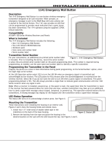
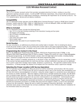
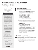
Squeeze to
Remove Cover
Squeeze to
Remove Cover
Figure 1: 1114 Wireless Four-Zone Expander
InstallatIon GuIde

Digital Monitoring Products 1114 Installation Guide
2
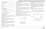
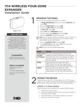
Installing the 1114
Mountthe1114onaatsurfacesuchasawallorsingle-gangbox.WhenusingtheoptionalModel376Lplug-inpower
supply, mount the 1114 near a wall outlet. See Figure 2 for mounting hole locations.
Red LED
(Survey)
Ta mper
Switch
Mounting Holes
+
3.0V
Lithium
Battery
—
Internal
Antenna
Location
- +
DC Power
2-position
Terminal Block
EXT BAT
Figure 2: 1114 Four-Zone Expander PCB
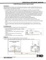
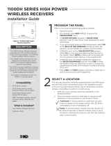
1114 Zone Wiring
It is recommended to locate zone devices within 100 feet of the
1114zoneexpander.Use22or18AWGwiretocompletethe
connections between the 1114 zone expander Zones 1 through
4andeachelddevice.Eachzoneterminateswithoneofthe
included470kEOLresistorsasshown.
Powering the 1114
The 1114 can be powered by:
• CR123A3.0VDCbattery
• Model376Lplug-inpowersupply
• 12VDCPowerSupply
Note: When setting up a wireless system, it is recommended to program zones and connect the receiver before
installing batteries in the 1114 or connecting the optional power supply.
Battery Power
Observepolaritywheninstallingthebattery.Useonly3.0VLithiumbatteries,DMPModelCR123,ortheequivalent
battery from a local retail outlet. Do not connect the power supply when operating using battery power.
1. Squeeze the cover left and right sides together to remove. See Figure 1.
2. Install the supplied jumper on the two J1 pins next to BAT to enable battery operation.
Note: Battery operation is not enabled if the jumper is on the J1 pins next to EXT.
3. If replacing the battery, remove the old battery and dispose of it properly.
4.Placethe3.0VLithiumbatteryintheholderandpressintoplace.SeeFigure2forBatterylocation.
5.Snapthecoverbackintoplace.
Caution:Properlydisposeofusedbatteries.Donotrecharge,disassemble,heatabove212°F(100°C),
orincinerate.Riskofre,explosion,andburns.
470k EOL
Figure 3: 1114 Zone Terminals

1114 Installation Guide Digital Monitoring Products
3
Battery Life Expectancy
Typicalbatterylifeexpectancyforthe1114isthreeyears.RefertotheXR500SeriesProgrammingGuide
(LT-0679),XR100SeriesProgrammingGuide(LT-0896),theXT30/XT50SeriesProgrammingGuide(LT-0981),theXTL
ProgrammingGuide(LT-1108),ortheXTLNProgrammingGuide(LT-1221)asneeded.
DMP wireless equipment uses two-way communication to extend battery life.
The following situation can extend battery life expectancy:
• Extendtransmittersupervisiontimeinpanelprogramming.
The following situations can reduce battery life expectancy:
• Ifareceiverisunpluggedornotinstalled.
Note:Transmitterscontinuetosendsupervisionmessagesuntilareceiverreturnsanacknowledgement.
Afteranhourthetransmitteronlyattemptsasupervisionmessageevery60minutes.
• Wheninstalledinextremehotorcoldenvironments.
Optional External DC Plug-in Power Supply
WhenusingtheoptionalModel376Lplug-inDCpowersupply,mountthe
1114 near a wall outlet. Do not install a battery when operating using
the plug-in power supply. The power supply does not charge the battery.
Use the following steps to connect the plug-in power supply:
1. Squeeze the left and right cover sides together to remove. See
Figure 1.
2. Install the supplied jumper on the two J1 pins next to EXT to
enable power supply operation.
Note: Power supply operation is not enabled if the jumper is on the
J1 pins next to BAT.
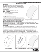
3.WirethepowersupplytotheJ2terminalblock.ConnecttheBlackwirewiththeWhitestripetothepositive
terminalandtheBlackwiretothenegativeterminal.SeeFigure4.
4.Snapthecoverbackintoplace.
5.PlugtheModel376Lpowersupplyintoa110VoltACoutlet.
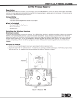
Optional External 12 VDC Power Supply
The1114canalsobepoweredfroma12VDCpowersupplysuchasaDMPModel505-12.Use22AWGwiretoconnect
to the power supply. Do not install a battery when operating using the external power supply. The power supply does
not charge the battery.
Use the following steps to connect the power supply:
1. Squeeze the left and right cover sides together to remove. See
Figure 1.
2. Install the supplied jumper on the two J1 pins next to EXT to
enable power supply operation.
Note: Power supply operation is not enabled if the jumper is on
the J1 pins next to BAT.
3.Using22AWGwire,connecttheJ2terminalblocktotheJ6
terminalonthe505-12powersupplyPCB.SeeFigure5.
4.Observepositiveandnegativepolarityonallconnections.
5.Snapthecoverbackintoplace.
J2
DC
Plug-in
Power
Supply
DC Power
2-position
Terminal Block
- +
- +
Black Wire
with White
Stripe
to Positive
Black Wire
to Negative
Figure 4: 1114 Side View
J6
+ DC -
505-12 Power
Supply
12 VDC
22 AWG Wire
DC Power
2-position
Terminal Block
- +
J2
- +
Figure 5: Power Supply Connection

LT-0705 © 2014 Digital Monitoring Products, Inc.
14405
800-641-4282
www.dmp.com 2500 North Partnership Boulevard
Specications
Battery
LifeExpectancy 3years
Type 3.0VLithiumCR123A
SeeBatteryLifeExpectancyforfulldetails.
FrequencyRange 903-927MHz
Dimensions 4.65”Lx3.1”Wx1.4”H
Color White
HousingMaterial FlameretardantABS
Accessories
CR123 DMP3.0VLithiumBattery
376L DCPlug-inPowerSupply
505-12 12VDCPowerSupply
Compatibility
1100D Wireless Receiver using version 104
1100DHWirelessHighPowerReceiverusingversion105
1100DIWirelessIn-lineReceiverusingversion105
1100X Wireless Receiver using version 104
1100XHWirelessHighPowerReceiverusingversion105
XTLPanelwithintegratedwirelessreceiverusingversion104
XTLNPanelwithintegratedwirelessreceiver
XT30/XT50Seriespanelwithintegratedwirelessreceiver
using version 101
Patents
U.S.PatentNo.7,239,236
Listings and Approvals
FCCPart15RegistrationIDCCKPC0101
ICRegistrationID5251A-PC0101
FCC Information
ThisdevicecomplieswithPart15oftheFCCRules.Operationissubjecttothefollowingtwoconditions
(1)Thisdevicemaynotcauseharmfulinterference,and
(2)thisdevicemustacceptanyinterferencereceived,includinginterferencethatmaycauseundesiredoperation.
Theantennausedforthistransmittermustbeinstalledtoprovideaseparationdistanceofatleast20cm(7.874in.)
from all persons. It must not be located or operated in conjunction with any other antenna or transmitter.
Changesormodicationsmadebytheuserandnotexpresslyapprovedbythepartyresponsibleforcompliancecould
void the user’s authority to operate the equipment.
Note: This equipment has been tested and found to comply with the limits for a Class B digital device, pursuant to
part15oftheFCCRules.Theselimitsaredesignedtoprovidereasonableprotectionagainstharmfulinterference
in a residential installation. This equipment generates, uses and can radiate radio frequency energy and, if not
installed and used in accordance with the instructions, may cause harmful interference to radio communications.
However,thereisnoguaranteethatinterferencewillnotoccurinaparticularinstallation.Ifthisequipmentdoes
cause harmful interference to radio or television reception, which can be determined by turning the equipment off
and on, the user is encouraged to try to correct the interference by one or more of the following measures:
- Reorient or relocate the receiving antenna.
- Increase the separation between the equipment and receiver.
- Connect the equipment into an outlet on a circuit different from that to which the receiver is connected.
- Consultthedealeroranexperiencedradio/TVtechnicianforhelp.
/